EP0000131A1 - Verfahren und Vorrichtung zur Schmierung von Kompressoren - Google Patents
Verfahren und Vorrichtung zur Schmierung von Kompressoren Download PDFInfo
- Publication number
- EP0000131A1 EP0000131A1 EP78100127A EP78100127A EP0000131A1 EP 0000131 A1 EP0000131 A1 EP 0000131A1 EP 78100127 A EP78100127 A EP 78100127A EP 78100127 A EP78100127 A EP 78100127A EP 0000131 A1 EP0000131 A1 EP 0000131A1
- Authority
- EP
- European Patent Office
- Prior art keywords
- bearings
- compressor
- gear
- oil
- valve
- Prior art date
- Legal status (The legal status is an assumption and is not a legal conclusion. Google has not performed a legal analysis and makes no representation as to the accuracy of the status listed.)
- Granted
Links
- 238000005461 lubrication Methods 0.000 title claims abstract description 18
- 238000000034 method Methods 0.000 title claims description 9
- 230000006835 compression Effects 0.000 claims abstract description 30
- 238000007906 compression Methods 0.000 claims abstract description 30
- 238000007789 sealing Methods 0.000 claims description 7
- 239000012530 fluid Substances 0.000 claims description 3
- 230000001050 lubricating effect Effects 0.000 claims description 2
- 210000000056 organ Anatomy 0.000 abstract description 5
- 240000008042 Zea mays Species 0.000 description 2
- 239000013529 heat transfer fluid Substances 0.000 description 2
- 239000000203 mixture Substances 0.000 description 2
- 101100536354 Drosophila melanogaster tant gene Proteins 0.000 description 1
- WYTGDNHDOZPMIW-RCBQFDQVSA-N alstonine Natural products C1=CC2=C3C=CC=CC3=NC2=C2N1C[C@H]1[C@H](C)OC=C(C(=O)OC)[C@H]1C2 WYTGDNHDOZPMIW-RCBQFDQVSA-N 0.000 description 1
- 230000005494 condensation Effects 0.000 description 1
- 238000009833 condensation Methods 0.000 description 1
- 239000002245 particle Substances 0.000 description 1
- QEVHRUUCFGRFIF-MDEJGZGSSA-N reserpine Chemical compound O([C@H]1[C@@H]([C@H]([C@H]2C[C@@H]3C4=C(C5=CC=C(OC)C=C5N4)CCN3C[C@H]2C1)C(=O)OC)OC)C(=O)C1=CC(OC)=C(OC)C(OC)=C1 QEVHRUUCFGRFIF-MDEJGZGSSA-N 0.000 description 1
- 125000006850 spacer group Chemical group 0.000 description 1
- XLYOFNOQVPJJNP-UHFFFAOYSA-N water Substances O XLYOFNOQVPJJNP-UHFFFAOYSA-N 0.000 description 1
Images

Classifications
-
- F—MECHANICAL ENGINEERING; LIGHTING; HEATING; WEAPONS; BLASTING
- F04—POSITIVE - DISPLACEMENT MACHINES FOR LIQUIDS; PUMPS FOR LIQUIDS OR ELASTIC FLUIDS
- F04C—ROTARY-PISTON, OR OSCILLATING-PISTON, POSITIVE-DISPLACEMENT MACHINES FOR LIQUIDS; ROTARY-PISTON, OR OSCILLATING-PISTON, POSITIVE-DISPLACEMENT PUMPS
- F04C18/00—Rotary-piston pumps specially adapted for elastic fluids
- F04C18/08—Rotary-piston pumps specially adapted for elastic fluids of intermeshing-engagement type, i.e. with engagement of co-operating members similar to that of toothed gearing
- F04C18/12—Rotary-piston pumps specially adapted for elastic fluids of intermeshing-engagement type, i.e. with engagement of co-operating members similar to that of toothed gearing of other than internal-axis type
- F04C18/14—Rotary-piston pumps specially adapted for elastic fluids of intermeshing-engagement type, i.e. with engagement of co-operating members similar to that of toothed gearing of other than internal-axis type with toothed rotary pistons
- F04C18/16—Rotary-piston pumps specially adapted for elastic fluids of intermeshing-engagement type, i.e. with engagement of co-operating members similar to that of toothed gearing of other than internal-axis type with toothed rotary pistons with helical teeth, e.g. chevron-shaped, screw type
-
- F—MECHANICAL ENGINEERING; LIGHTING; HEATING; WEAPONS; BLASTING
- F04—POSITIVE - DISPLACEMENT MACHINES FOR LIQUIDS; PUMPS FOR LIQUIDS OR ELASTIC FLUIDS
- F04C—ROTARY-PISTON, OR OSCILLATING-PISTON, POSITIVE-DISPLACEMENT MACHINES FOR LIQUIDS; ROTARY-PISTON, OR OSCILLATING-PISTON, POSITIVE-DISPLACEMENT PUMPS
- F04C29/00—Component parts, details or accessories of pumps or pumping installations, not provided for in groups F04C18/00 - F04C28/00
- F04C29/02—Lubrication; Lubricant separation
- F04C29/021—Control systems for the circulation of the lubricant
-
- Y—GENERAL TAGGING OF NEW TECHNOLOGICAL DEVELOPMENTS; GENERAL TAGGING OF CROSS-SECTIONAL TECHNOLOGIES SPANNING OVER SEVERAL SECTIONS OF THE IPC; TECHNICAL SUBJECTS COVERED BY FORMER USPC CROSS-REFERENCE ART COLLECTIONS [XRACs] AND DIGESTS
- Y10—TECHNICAL SUBJECTS COVERED BY FORMER USPC
- Y10S—TECHNICAL SUBJECTS COVERED BY FORMER USPC CROSS-REFERENCE ART COLLECTIONS [XRACs] AND DIGESTS
- Y10S418/00—Rotary expansible chamber devices
- Y10S418/01—Non-working fluid separation
Definitions
- the present invention relates to a method of lubricating compressors, in particular of the helical type.
- the quantity of oil necessary for this purpose is a function of the quantity of calories to be removed, since the temperature of the mixture of air and oil discharged from the compress must be within a well-defined temperature range, in order to avoid water condensation in the oil tank on the one hand, and auto-ignition of the air-oil mixture on the other.
- the Demand therefore sought to reduce the quantity of oil when idling while reducing the power consumed at such a rate much more significantly than in conventional compressors, and this by implementing a simple secondary lubrication circuit and high reliability.
- the object of the invention is therefore a lubrication process of a compressor for a fluid of the type comprising a compression chamber in which at least two rotors are rotated by at least one gear and each rotate on two end bearings, said bearings and gear being housed in flanges forming volute office, namely a suction flange and a discharge flange, said gear being linked to a driving shaft, the sealing of said shaft being ensured, suction side, by a friction grain seal, characterized in that, in operating speed under load, said compression chamber, said bearings, said gear, as well as said friction grain seal are supplied with oil coming from a separating tank and under a high pressure and substantially equal to that prevailing in said separating tank, while under idling conditions said compression chamber and said bearings housed in said delivery flange are supplied with oil from said tank s spacer but under low pressure, the bearings, said gear, as well as said friction grain seal housed in said suction flange being independently supplied with oil coming directly from the exhaust or
- the invention also relates to a device for implementing the method according to claim 1, characterized in that it comprises two circuits, a main circuit and a secondary circuit, said main circuit comprising a pipe having its source in said separator tank of oil and subdivided into three branches, a first branch supplying said compression chamber, a second branch supplying said bearings, said gear and said friction grain seal housed in said suction flange via a valve, and a third branch supplying said bearings housed in said delivery flange, said secondary circuit comprising a pipe originating directly from the compressor exhaust, leading to a valve, then subdivided into two branches, a first branch supplying the bearings and the gear housed in said suction flange, by through a valve, and a second bypass supplying the friction grain seal.
- the compressor lubricated in the known manner and represented in FIG. 1 therefore comprises a compression block 1 in which two helical rotors rotate, a male rotor 2 and a female rotor 3, the male rotor 2 being driven by means of a motor 4 and by by means of a gear 5 cooperating with a universal joint 6, housings such as 7 ensuring sealing.
- This pipe 9 opens into an oil separator tank 10 above, of course, the oil level 11.
- the compressed air is therefore evacuated to the place of use via the line 12 according to the arrows, after having abandoned the entrained oil particles at the level of a filter 13.
- the suction 8 is therefore partially obstructed in order to reduce the pressure in the separator tank 10 and consequently the compression power.
- the Applicant has therefore sought to remedy such a drawback and to significantly reduce the power consumed when idling, and this by implementing a simple, inexpensive and reliable additional lubrication circuit.
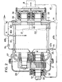
- the compressor shown in FIG. 2 comprises a casing 20 or compression block inside which two rotors move in rotation, a male rotor 21 and a female rotor 22 of helical type. These rotors rotate on ball or roller bearings, namely bearings 23 and 24 for the male rotor 21 and bearings 25 and 26 for the female rotor 22.
- Such bearings are housed in flanges 27 and 28, the flange 27 acting as a suction scroll, while the flange 28 assumes the role of discharge or exhaust scroll.
- the male rotor 21 has a shaft end (not shown) on which is keyed a multiplier gear train 29 linked to a driving shaft 30 journalled on bearings 31 and 32, the seal being ensured by means of a seal grain rubbing 33.
- two lubrication circuits are used, a main circuit and a secondary or additional circuit.
- This bypass 40b can be opened or closed by a valve V2.
- a third branch 40c supplying the bearings 24 and 26 via a conduit 42.
- a second bypass 43b supplying the friction seal 33 as well as the bearing 32.
- the pressure drops in said branches are predetermined so that the oil flow is sufficient.
- the valve V2 is closed, but the oil still feeds the compression chamber 20, as well as the various organs on the discharge side by the branches 40a and 40c according, obviously, to a low flow rate, however sufficient.
- the secondary lubrication circuit has a high cor..ductance, taking into account the relatively low pressure prevailing at point B.
- valves V1 and V3 close, the valve V2 opens and so on.
- the no-load power is divided by a coefficient at least equal to 2.5.
Landscapes
- Engineering & Computer Science (AREA)
- Mechanical Engineering (AREA)
- General Engineering & Computer Science (AREA)
- Applications Or Details Of Rotary Compressors (AREA)
- Compressor (AREA)
- Control Of Positive-Displacement Pumps (AREA)
- Compressors, Vaccum Pumps And Other Relevant Systems (AREA)
Applications Claiming Priority (2)
| Application Number | Priority Date | Filing Date | Title |
|---|---|---|---|
| FR7718646 | 1977-06-17 | ||
| FR7718646A FR2401338B1 (de) | 1977-06-17 | 1977-06-17 |
Publications (2)
| Publication Number | Publication Date |
|---|---|
| EP0000131A1 true EP0000131A1 (de) | 1979-01-10 |
| EP0000131B1 EP0000131B1 (de) | 1980-11-26 |
Family
ID=9192226
Family Applications (1)
| Application Number | Title | Priority Date | Filing Date |
|---|---|---|---|
| EP78100127A Expired EP0000131B1 (de) | 1977-06-17 | 1978-06-12 | Verfahren und Vorrichtung zur Schmierung von Kompressoren |
Country Status (5)
| Country | Link |
|---|---|
| US (1) | US4173440A (de) |
| EP (1) | EP0000131B1 (de) |
| DE (1) | DE2860337D1 (de) |
| FR (1) | FR2401338B1 (de) |
| IT (1) | IT1209443B (de) |
Cited By (8)
| Publication number | Priority date | Publication date | Assignee | Title |
|---|---|---|---|---|
| WO1983003641A1 (en) * | 1982-04-13 | 1983-10-27 | Glanvall, Rune | Compressor of hermetical type |
| GB2205902B (en) * | 1987-06-11 | 1992-01-15 | Ingersoll Rand Co | A lubrication arrangement in an air compressor |
| EP1846642A4 (de) * | 2005-02-07 | 2011-11-23 | Carrier Corp | Schraubenverdichterschmierung |
| WO2011110475A3 (de) * | 2010-03-08 | 2012-07-26 | Bitzer Kühlmaschinenbau Gmbh | Schraubenverdichter |
| BE1023673B1 (nl) * | 2015-12-11 | 2017-06-12 | Atlas Copco Airpower Naamloze Vennootschap | Werkwijze voor het regelen van de vloeistofinjectie van een compressorinrichting, een vloeistofgeïnjecteerde compressorinrichting en een vloeistofgeïnjecteerd compressorelement |
| WO2017096439A1 (en) * | 2015-12-11 | 2017-06-15 | Atlas Copco Airpower, Naamloze Vennootschap | Method for regulating the liquid injection of a compressor or expander device, a liquid-injected compressor or expander device, and a liquid-injected compressor or expander element |
| WO2017096438A1 (en) * | 2015-12-11 | 2017-06-15 | Atlas Copco Airpower, Naamloze Vennootschap | Method for regulating the liquid injection of a compressor, a liquid-injected compressor and a liquid-injected compressor element |
| BE1023714B1 (nl) * | 2015-12-11 | 2017-06-26 | Atlas Copco Airpower Naamloze Vennootschap | Werkwijze voor het regelen van de vloeistofinjectie van een compressor- of expanderinrichting, een vloeistofgeïnjecteerde compressor- of expanderinrichting en een vloeistofgeïnjecteerd compressor- of expanderelement |
Families Citing this family (20)
| Publication number | Priority date | Publication date | Assignee | Title |
|---|---|---|---|---|
| US4341506A (en) * | 1979-08-14 | 1982-07-27 | Gutehoffnungshutte Sterkrade A.G. | Apparatus for the generation of compressed air |
| US4439121A (en) * | 1982-03-02 | 1984-03-27 | Dunham-Bush, Inc. | Self-cleaning single loop mist type lubrication system for screw compressors |
| US4768355A (en) * | 1987-01-27 | 1988-09-06 | Ford Motor Company | Accumulator with refrigerant processing cartridge for automotive air conditioning system |
| US4800737A (en) * | 1987-04-17 | 1989-01-31 | Ford Motor Company | Automotive air conditioning system accumulator with refrigerant processing cartridge including evaporator pressure regulator |
| JPH02275089A (ja) * | 1989-04-13 | 1990-11-09 | Kobe Steel Ltd | スクリュ式真空ポンプ |
| US5028220A (en) * | 1990-08-13 | 1991-07-02 | Sullair Corpoation | Cooling and lubrication system for a vacuum pump |
| US6318959B1 (en) * | 1998-12-22 | 2001-11-20 | Unozawa-Gumi Iron Works, Ltd. | Multi-stage rotary vacuum pump used for high temperature gas |
| DE20015744U1 (de) * | 2000-09-12 | 2001-01-25 | Werner Rietschle GmbH + Co. KG, 79650 Schopfheim | Pumpe mit Wassereinspeisung |
| BE1014297A3 (nl) * | 2001-07-13 | 2003-08-05 | Atlas Copco Airpower Nv | Watergeinjecteerde schroefcompressor. |
| US6520758B1 (en) | 2001-10-24 | 2003-02-18 | Ingersoll-Rand Company | Screw compressor assembly and method including a rotor having a thrust piston |
| US20040112679A1 (en) * | 2002-12-13 | 2004-06-17 | Centers Steven D. | System and method for lubricant flow control in a variable speed compressor package |
| US7553142B2 (en) * | 2004-02-25 | 2009-06-30 | Carrier Corporation | Lubrication system for compressor |
| US20090129956A1 (en) * | 2007-11-21 | 2009-05-21 | Jean-Louis Picouet | Compressor System and Method of Lubricating the Compressor System |
| JP5103246B2 (ja) * | 2008-01-24 | 2012-12-19 | 株式会社神戸製鋼所 | スクリュ圧縮機 |
| CN102725532B (zh) * | 2010-01-29 | 2015-09-23 | Ulvac机工株式会社 | 泵 |
| US10436104B2 (en) * | 2014-05-23 | 2019-10-08 | Eaton Intelligent Power Limited | Supercharger |
| CN107002679B (zh) * | 2014-12-17 | 2019-12-13 | 开利公司 | 具有油关闭阀的螺杆压缩机和方法 |
| CN104963870A (zh) * | 2015-07-27 | 2015-10-07 | 珠海格力电器股份有限公司 | 排气轴承座、螺杆压缩机及空调机组 |
| CN110219803B (zh) * | 2019-07-18 | 2024-09-06 | 珠海格力节能环保制冷技术研究中心有限公司 | 压缩机、空调器 |
| US11448220B2 (en) | 2019-09-27 | 2022-09-20 | Ingersoll-Rand Industrial U.S., Inc. | Airend having a lubricant flow valve and controller |
Citations (7)
| Publication number | Priority date | Publication date | Assignee | Title |
|---|---|---|---|---|
| FR1429488A (fr) * | 1964-03-30 | 1966-02-25 | Gardner Denver Co | Système de commande d'un compresseur |
| FR1562714A (de) * | 1968-05-15 | 1969-04-04 | ||
| FR1574479A (de) * | 1968-07-17 | 1969-07-11 | ||
| US3482768A (en) * | 1968-02-28 | 1969-12-09 | Gardner Denver Co | Compressor control system |
| US3653191A (en) * | 1969-10-16 | 1972-04-04 | Gardner Denver Co | Receiver-separator unit for liquid injected gas compressor |
| FR2151406A5 (de) * | 1971-08-25 | 1973-04-13 | Hokuetsu Kogyo Co | |
| US4063855A (en) * | 1976-05-03 | 1977-12-20 | Fuller Company | Compressor capacity and lubrication control system |
Family Cites Families (3)
| Publication number | Priority date | Publication date | Assignee | Title |
|---|---|---|---|---|
| GB1212015A (en) * | 1967-05-03 | 1970-11-11 | Svenksa Rotor Maskiner Aktiebo | Improvements in and relating to meshing screw-rotor compressors |
| US3556697A (en) * | 1969-04-10 | 1971-01-19 | Ingersoll Rand Co | Sealing arrangement for vacuum pump |
| DE2123011A1 (de) * | 1971-05-10 | 1972-12-14 | Audi NSU Auto Union AG, 7107 Neckars ulm, Wankel GmbH, 8990 Lindau | Kreiskolben Brennkraftmaschine mit ölgekühltem Kolben |
-
1977
- 1977-06-17 FR FR7718646A patent/FR2401338B1/fr not_active Expired
-
1978
- 1978-06-08 US US05/913,924 patent/US4173440A/en not_active Expired - Lifetime
- 1978-06-12 EP EP78100127A patent/EP0000131B1/de not_active Expired
- 1978-06-12 IT IT7824453A patent/IT1209443B/it active
- 1978-06-12 DE DE7878100127T patent/DE2860337D1/de not_active Expired
Patent Citations (7)
| Publication number | Priority date | Publication date | Assignee | Title |
|---|---|---|---|---|
| FR1429488A (fr) * | 1964-03-30 | 1966-02-25 | Gardner Denver Co | Système de commande d'un compresseur |
| US3482768A (en) * | 1968-02-28 | 1969-12-09 | Gardner Denver Co | Compressor control system |
| FR1562714A (de) * | 1968-05-15 | 1969-04-04 | ||
| FR1574479A (de) * | 1968-07-17 | 1969-07-11 | ||
| US3653191A (en) * | 1969-10-16 | 1972-04-04 | Gardner Denver Co | Receiver-separator unit for liquid injected gas compressor |
| FR2151406A5 (de) * | 1971-08-25 | 1973-04-13 | Hokuetsu Kogyo Co | |
| US4063855A (en) * | 1976-05-03 | 1977-12-20 | Fuller Company | Compressor capacity and lubrication control system |
Cited By (14)
| Publication number | Priority date | Publication date | Assignee | Title |
|---|---|---|---|---|
| WO1983003641A1 (en) * | 1982-04-13 | 1983-10-27 | Glanvall, Rune | Compressor of hermetical type |
| GB2205902B (en) * | 1987-06-11 | 1992-01-15 | Ingersoll Rand Co | A lubrication arrangement in an air compressor |
| EP1846642A4 (de) * | 2005-02-07 | 2011-11-23 | Carrier Corp | Schraubenverdichterschmierung |
| WO2011110475A3 (de) * | 2010-03-08 | 2012-07-26 | Bitzer Kühlmaschinenbau Gmbh | Schraubenverdichter |
| CN102792027A (zh) * | 2010-03-08 | 2012-11-21 | 比泽尔制冷设备有限公司 | 螺杆式压缩机 |
| US8870555B2 (en) | 2010-03-08 | 2014-10-28 | Bitzer Kuehlmaschinenbau Gmbh | Screw compressor |
| CN102792027B (zh) * | 2010-03-08 | 2015-05-13 | 比泽尔制冷设备有限公司 | 螺杆式压缩机 |
| BE1023673B1 (nl) * | 2015-12-11 | 2017-06-12 | Atlas Copco Airpower Naamloze Vennootschap | Werkwijze voor het regelen van de vloeistofinjectie van een compressorinrichting, een vloeistofgeïnjecteerde compressorinrichting en een vloeistofgeïnjecteerd compressorelement |
| WO2017096439A1 (en) * | 2015-12-11 | 2017-06-15 | Atlas Copco Airpower, Naamloze Vennootschap | Method for regulating the liquid injection of a compressor or expander device, a liquid-injected compressor or expander device, and a liquid-injected compressor or expander element |
| WO2017096438A1 (en) * | 2015-12-11 | 2017-06-15 | Atlas Copco Airpower, Naamloze Vennootschap | Method for regulating the liquid injection of a compressor, a liquid-injected compressor and a liquid-injected compressor element |
| BE1023714B1 (nl) * | 2015-12-11 | 2017-06-26 | Atlas Copco Airpower Naamloze Vennootschap | Werkwijze voor het regelen van de vloeistofinjectie van een compressor- of expanderinrichting, een vloeistofgeïnjecteerde compressor- of expanderinrichting en een vloeistofgeïnjecteerd compressor- of expanderelement |
| EP3505764A1 (de) * | 2015-12-11 | 2019-07-03 | ATLAS COPCO AIRPOWER, naamloze vennootschap | Vorrichtung für flüssigkeitseingespritzten verdichter oder expander und element eines flüssigkeitseingespritzten verdichters oder expanders |
| US10920777B2 (en) | 2015-12-11 | 2021-02-16 | Atlas Copco Airpower, Naamloze Vennootschap | Method for regulating the liquid injection of a compressor or expander device, a liquid-injected compressor or expander device, and a liquid-injected compressor or expander element |
| US11614088B2 (en) | 2015-12-11 | 2023-03-28 | Atlas Copco Airpower, Naamloze Vennootschap | Method of controlling the temperature and mass flow of a liquid injected into the bearings and compressor space of a compressor using two separated liquid supplies |
Also Published As
| Publication number | Publication date |
|---|---|
| IT1209443B (it) | 1989-08-30 |
| DE2860337D1 (en) | 1981-02-12 |
| EP0000131B1 (de) | 1980-11-26 |
| FR2401338A1 (de) | 1979-03-23 |
| FR2401338B1 (de) | 1980-03-14 |
| IT7824453A0 (it) | 1978-06-12 |
| US4173440A (en) | 1979-11-06 |
Similar Documents
| Publication | Publication Date | Title |
|---|---|---|
| EP0000131B1 (de) | Verfahren und Vorrichtung zur Schmierung von Kompressoren | |
| BE1014892A5 (fr) | Compresseur a vis sans huile. | |
| EP0401741B1 (de) | Zweistufige Trockenprimärpumpe | |
| EP2619419B1 (de) | System zum unterdrucksetzen der lagerkammern von turbinenmotormaschinen mit luft aus dem ansaugkanal | |
| EP0368122B1 (de) | Mehrstufige Roots-Vakuumpumpe | |
| US4422295A (en) | Lubricating system for turbo-chargers | |
| US5028220A (en) | Cooling and lubrication system for a vacuum pump | |
| WO2006013636A1 (ja) | 多系統潤滑式スクリュー圧縮機の潤滑油供給システム及び運転方法 | |
| FR2936273A1 (fr) | Procede et systeme de lubrification d'une turbomachine | |
| FR2675213A1 (fr) | Systeme formant barriere pour l'huile de lubrification des paliers d'un compresseur centrifuge muni de joints d'etancheite a labyrinthe installe dans un environnement confine. | |
| US4594992A (en) | Supercharger of an internal combustion engine having Roots pump | |
| US4995797A (en) | Rotary screw vacuum pump with pressure controlled valve for lubrication/sealing fluid | |
| FR2518662A1 (fr) | Dispositif d'approvisionnement en huile pour compresseur a vis | |
| WO2010097537A1 (fr) | Dispositif de séparation de lubrifiant d'un mélange lubrifiant-gaz frigorigène refoulé à partir d'au moins un compresseur frigorifique | |
| CN1117755A (zh) | 摇动型旋转式压缩机 | |
| CH377476A (fr) | Groupe turbo-compresseur | |
| FR2565295A1 (fr) | Pompe a vide rotative etanchee dans l'huile | |
| FR2569780A1 (fr) | Procede et dispositif d'etancheite et de pressurisation pour sorties d'arbres de compresseur d'air exempt d'huile | |
| JPS61152990A (ja) | スクリユ−真空ポンプ | |
| JPS57135292A (en) | Screw compressor | |
| FR2556775A1 (fr) | Dispositif de limitation de la pression dans un circuit de lubrification de moteur | |
| JPS63285279A (ja) | 真空ポンプの軸封装置 | |
| JPH0868386A (ja) | スクロール型空気圧縮機 | |
| EP1267077A1 (de) | Zahnradpumpe mit drei Wellen | |
| FR2845432A1 (fr) | Compresseur a piston axial de co2 pour des installations de climatisation de vehicules automobiles |
Legal Events
| Date | Code | Title | Description |
|---|---|---|---|
| PUAI | Public reference made under article 153(3) epc to a published international application that has entered the european phase |
Free format text: ORIGINAL CODE: 0009012 |
|
| AK | Designated contracting states |
Kind code of ref document: A1 Designated state(s): BE DE FR GB NL SE |
|
| 17P | Request for examination filed | ||
| GRAA | (expected) grant |
Free format text: ORIGINAL CODE: 0009210 |
|
| AK | Designated contracting states |
Kind code of ref document: B1 Designated state(s): BE DE FR GB NL SE |
|
| RAP2 | Party data changed (patent owner data changed or rights of a patent transferred) |
Owner name: ALSTHOM-ATLANTIQUE SOCIETE ANONYME DITE: |
|
| REF | Corresponds to: |
Ref document number: 2860337 Country of ref document: DE Date of ref document: 19810212 |
|
| PGFP | Annual fee paid to national office [announced via postgrant information from national office to epo] |
Ref country code: FR Payment date: 19840322 Year of fee payment: 7 |
|
| PGFP | Annual fee paid to national office [announced via postgrant information from national office to epo] |
Ref country code: DE Payment date: 19840425 Year of fee payment: 7 |
|
| PGFP | Annual fee paid to national office [announced via postgrant information from national office to epo] |
Ref country code: SE Payment date: 19840630 Year of fee payment: 7 Ref country code: BE Payment date: 19840630 Year of fee payment: 7 |
|
| PGFP | Annual fee paid to national office [announced via postgrant information from national office to epo] |
Ref country code: NL Payment date: 19860630 Year of fee payment: 9 |
|
| PG25 | Lapsed in a contracting state [announced via postgrant information from national office to epo] |
Ref country code: SE Effective date: 19870613 |
|
| BERE | Be: lapsed |
Owner name: ALSTHOM-ATLANTIQUE Effective date: 19870630 |
|
| PG25 | Lapsed in a contracting state [announced via postgrant information from national office to epo] |
Ref country code: NL Effective date: 19880101 |
|
| NLV4 | Nl: lapsed or anulled due to non-payment of the annual fee | ||
| PG25 | Lapsed in a contracting state [announced via postgrant information from national office to epo] |
Ref country code: FR Free format text: LAPSE BECAUSE OF NON-PAYMENT OF DUE FEES Effective date: 19880226 |
|
| PG25 | Lapsed in a contracting state [announced via postgrant information from national office to epo] |
Ref country code: DE Effective date: 19880301 |
|
| GBPC | Gb: european patent ceased through non-payment of renewal fee | ||
| REG | Reference to a national code |
Ref country code: FR Ref legal event code: ST |
|
| PG25 | Lapsed in a contracting state [announced via postgrant information from national office to epo] |
Ref country code: GB Effective date: 19881117 |
|
| PG25 | Lapsed in a contracting state [announced via postgrant information from national office to epo] |
Ref country code: BE Effective date: 19890630 |
|
| EUG | Se: european patent has lapsed |
Ref document number: 78100127.6 Effective date: 19880113 |
|
| PLBE | No opposition filed within time limit |
Free format text: ORIGINAL CODE: 0009261 |
|
| STAA | Information on the status of an ep patent application or granted ep patent |
Free format text: STATUS: NO OPPOSITION FILED WITHIN TIME LIMIT |