EP0000281A1 - Châssis-support d'outils de travail sur un véhicule et méthode de fabrication d'un tel châssis - Google Patents
Châssis-support d'outils de travail sur un véhicule et méthode de fabrication d'un tel châssis Download PDFInfo
- Publication number
- EP0000281A1 EP0000281A1 EP78300094A EP78300094A EP0000281A1 EP 0000281 A1 EP0000281 A1 EP 0000281A1 EP 78300094 A EP78300094 A EP 78300094A EP 78300094 A EP78300094 A EP 78300094A EP 0000281 A1 EP0000281 A1 EP 0000281A1
- Authority
- EP
- European Patent Office
- Prior art keywords
- frame
- rails
- end portions
- frame according
- rail
- Prior art date
- Legal status (The legal status is an assumption and is not a legal conclusion. Google has not performed a legal analysis and makes no representation as to the accuracy of the status listed.)
- Granted
Links
Images


Classifications
-
- E—FIXED CONSTRUCTIONS
- E02—HYDRAULIC ENGINEERING; FOUNDATIONS; SOIL SHIFTING
- E02F—DREDGING; SOIL-SHIFTING
- E02F3/00—Dredgers; Soil-shifting machines
- E02F3/04—Dredgers; Soil-shifting machines mechanically-driven
- E02F3/28—Dredgers; Soil-shifting machines mechanically-driven with digging tools mounted on a dipper- or bucket-arm, i.e. there is either one arm or a pair of arms, e.g. dippers, buckets
- E02F3/36—Component parts
-
- B—PERFORMING OPERATIONS; TRANSPORTING
- B62—LAND VEHICLES FOR TRAVELLING OTHERWISE THAN ON RAILS
- B62D—MOTOR VEHICLES; TRAILERS
- B62D21/00—Understructures, i.e. chassis frame on which a vehicle body may be mounted
- B62D21/18—Understructures, i.e. chassis frame on which a vehicle body may be mounted characterised by the vehicle type and not provided for in groups B62D21/02 - B62D21/17
- B62D21/186—Understructures, i.e. chassis frame on which a vehicle body may be mounted characterised by the vehicle type and not provided for in groups B62D21/02 - B62D21/17 for building site vehicles or multi-purpose tractors
-
- B—PERFORMING OPERATIONS; TRANSPORTING
- B62—LAND VEHICLES FOR TRAVELLING OTHERWISE THAN ON RAILS
- B62D—MOTOR VEHICLES; TRAILERS
- B62D49/00—Tractors
- B62D49/06—Tractors adapted for multi-purpose use
Definitions
- This invention relates to frames for supporting implements on a vehicle and more particularly to such frames which are semi-integrated into an industrial vehicle equipped with earth handling implements fore and/or aft.
- An example of such a frame is a frame for supporting a front end loader and a rear mounted backhoe on an industrial tractor.
- Implement frames for industrial tractors may be broken down into three catagories.
- the earliest loaders on agricultural tractors were supported by attachable and detachable frames connected to the tractor chassis and dependent solely on the strength of the tractor chassis for their load carrying capability.
- the second class of frame is the semi-integrated which is permanently attached to the tractor chassis and particularly the axle housing while having sufficient structure in itself to partially support the implements attached thereto and absorb the loadings placed on the implements thereby reducing the loads on the tractor chassis.
- the third class of implement frame is the integrated frame which consists of a frame fabricated from the start to receive vehicle components such as axles, differential, transmission and engine, all of which are supported from and by the frame which is the support unit for all other components and assemblies including the vehicle wheels.
- the towers of the above frame are used to provide support for the lift arms and operating cylinders of a front end loader and the second interconnecting means may comprise a ballast weight if the vehicle is to be used as a loader only or part of a backhoe structure if the vehicle is to include a backhoe.
- a frame in accordance with the present invention is light in weight and capable of flexing in bending and torsion in order to dissipate the loading imposed on the frame by the implements without unduly loading the chassis to which the frame is secured.
- the stabilizing means between the towers ensures that when the towers flex forces are transmitted between the towers by the stabilizing means to equalize the loading on the towers and maintain a spaced relationship between the towers to ensure that the loader does not bind due to tower misalignment.
- the torsional characteristics of the frame can be varied by adjusting the flexibility of the stabilizing means.
- the stabilising means may include a stabilizing plate arranged to extend between the towers, said stabilizing plate having a hole therein generally centrally located to relieve stress therein resulting from torsional loading of the frame.
- the stabilizing plate may have a generally Z shaped cross-section when cut by a vertical plane extending generally longitudinally of the frame.
- the hole in the stabilizing plate is preferably elongated in shape, the direction of elongation being transverse relative to said frame.
- the axle housing attachment means preferably includes flexible members which allow relative twisting movement between said rails and axle housing during torsional loading of the frame. This further improves the frame's ability to absorb torsional loading.
- the second end portions of the rails are preferably provided with fastening means for securing said second interconnecting means in position, said fastening means including means for carrying shear loads.
- said shear load carrying means may comprise pins engaging said rails and second interconnecting means. These pins may be tapered at one end to facilitate engagement of the rail ends with the second interconnecting means.
- the fastening means preferably includes bolts for detachably securing the second interconnecting means to the rails.
- the means for connecting the rails to the chassis may comprise two rail brackets, one for attachment to each rail, and a chassis mounting plate for attachment between the rail brackets.
- the first interconnecting means comprises a steering axle support saddle arranged to extend between said first end portions.
- the rails of the frame are preferably structural channel mambers,. These rails may be orientated with their bases extending substantially vertically and their side flanges extending substantially horizontally, the steering axle support saddle being arranged to be secured to the bottom side flanges of the rails.
- a further important feature of the frame is that the rails diverge apart so that the frame has a tapering configuration when viewed in plan, the frame having a greater width at its second end portions than at its first end portions. This feature is of importance in enhancing the stability of the frame when supporting a backhoe structure. It removes the need to fabricate the rails with off-sets or bends in order to achieve the necessary frame width at the rear of the frame.
- the invention also provides a method of assembly a frame in accordance with the first aspect of the invention on a vehicle having a chassis including a transversely extending axle housing.
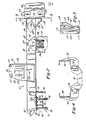
- FIG. 1 of the drawings there is generally designated an industrial tractor 10 having an implement frame 12 thereon in accordance with this invention.
- the tractor 10 is equipped with front and rear wheels 14 and 16.
- the forward end of the tractor 10 is equipped with a front end loader 18 and a backhoe 20 is located at the rear of the tractor.
- the backhoe 20 includes a bucket 22 pivotally connected to one end of a dipper stick 24 which in turn is pivotally connected at its upper end to a boom 26.
- a bucket 22 is swingable through a vertical arc relative to the dipper stick 24.
- a cylinder 28 is pivotally connected between the bucket 22 and dipper stick 24 for this purpose.
- the dipper stick 24 is pivoted through a vertical arc relative to the boom 26 by operation of a second cylinder 30 pivotally connected between the dipper stick 24 and the boom 26.
- the boom 26 is also swingable through a vertical arc and a third cylinder 32 is used to achieve this swing being pivotally connected between the boom 26 and the backhoe 20.
- the boom 26 is further swingable through a horizontal arc by virtue of a pair of cylinders, one 34 of which is visible in Figure 1, located on either side of the boom 26 and pivotally connected between the boom 26 and the backhoe 20.
- the boom 26 is pivotally mounted on a swing casting 36 which in turn is pivotally mounted on part of a backhoe structure 40 for pivotting about a vertical axis 38.
- the backhoe structure 40 is equipped with pivotally mounted stabilizers, one 42 of which is visible in Figure 1. These stabilizers are each mounted for movement through a vertical arc by mens of their own stabilizer cylinder 44 pivotally connected between the stabilizer 42 and the backhoe structure 40.
- the stabilizer 42 is seen in the extended position whereby both sides of the backhoe structure 40 are adequately supported by engagement of the stabilizers 42 with the ground.
- the loader 18 has a bucket 46 pivotally mounted at the forward end of loader arms, one 48 of which can be seen in Figure 1, which are located on either side of the tractor.
- the bucket 46 extends between the load arms 48 and is pivoted thereon.
- Each loader arm 48 is equipped with pivotally mounted cylinder 50 which is pivotally connected to the bucket 46 to change the bucket position or angle.
- the elevation and lowering of the arms 48 is brought about through a second cylinder 52 for each load arm 48, the second cylinder 52 being connected at one end in a pivotal fashion with the load arm 48 with which it is associated and at the other end to the implement frame 12.
- the implement frame 12 is equipped with a subframe or tower 54 which provides a pivotal mounting for the rear end of the load arms 48.
- the tractor 10 illustrated is a conventional agricultural type having an engine, transmission housing and back- axle housing which are bolted together to form the chassis, the sump of the engine being a structual component and constituting part of the chassis. Power is delivered from the engine to a differential located in the back axle housing via the transmission.
- the back axle housing provides support for the rear wheels 16 and the front wheels 14 are mounted on the chassis via the implement frame 12.
- Figures 2 and 3- show the implement frame 12 is equipped with a front axle support portion 56 which supports a conventional steering mechanism actuated by means of a steering wheel as illustrated in Figure 1.
- the tractor 10 in Figure 1 may be conveniently moved from one place to another under its own power as developed by its motor.
- the loader 18 When the loader 18 is being used the forces directed towards the implement frame 12 occur both from driving the vehicle 10 into a work pile with the bucket 46 orientated to fill the bucket 46 and by operation of the cylinders 50 and 52 on the bucket 46 and lift arms 48 in curling the bucket 46 and elevating the arms 48 as the work load is being engaged.
- the operation of the backhoe 20 is usually acccmpan- ied by extension of the stabilizers 42 to engage the ground whereby the backhoe structure 40 and stabilizers 42 receive the forces resulting from use of the backhoe 20 rather than the rear wheels 16 and the vehicle chassis therefrom.
- the operation of the backhoe 20 may result in a wide variety of stresses being applied to the tractor 10 but most particularly the implement frame 12. Torsional stresses arise when the backhoe 20 is pivoted horizontally as to dig on one side or the other of the tractor 10 rather than directly to the rear thereof.
- the above stress phenomenon is not limited to the operation of the backhoe 20 but may also be present in the operation of the front end loader 18 when one side of the bucket 46 encounters the load so as to eccentrically load the. bucket 46 and implement frame 12.
- Bending stress is also developed by the cantilever arrangement of the two implements 18 and 20 mounted on either extreme of the implement frame 12.
- loader frames have been supplemented with rear counterweight in order to counterbalance the load on the front of a tractor
- the bending stress transmitted to the tractor chassis to which the loader frames were previously attached as load receiving members resulted in localized bending stresses intermediate the length of the vehicle.
- Extreme cases resulted in actually breaking the vehicle in two.
- the above problem could be solved by using longitudinal frame members sufficiently strong so as not to bend and thereby not stress the chassis of the tractor, but such members were found to be excessively heavy.
- the addition of a backhoe in this operation imposed additional and extremely serious problems of localized bending stress. For example, where both implements, the front end loader and the backhoe, were used in conjunction to extract a mired vehicle the resultant bending stresses were a complete reversal of those experienced under normal operation conditions.
- the above operation is a desirable one for a vehicle of an industrial nature which should be suitable for use on job sights even where ground conditions are soft.
- the implement frame 12 should be suitable for enabling the front and rear implements 18 and 20 to literally raise the tractor 10 off the ground.
- prior art structures had addressed themselves to the problem of bending stresses which are accommodated in the implement frame, the same has not been true for the torsional stresses which tend to twist the implement frame longitudinal members, or rails, about their longitudinal axis.
- the prior art structures disclose reinforcing the implement frame to thereby make the frame more rigid and prevent movement of the implement frame.
- the primary longitudinal members or rails of the frame 12 illustrated are seen to be structural channel members 58 to which the tower assemblies 54 are welded.
- the towers contain bossed apertures for receiving pivots for the lift arm cylinders 52 in the lower bosses 60, for the lift arms 48 themselves in the upper left hand bosses 62, and for a member of the bucket linkage in the upper right hand boss 64.
- the towers 54 are located intermediate the ends of the channels 58.
- each channel 58 has an angle member 66 welded thereto and extending there beyond with apertures 68 ' therein for receiving the nose and grill of the tractor 10.
- the front axle support saddle 56 constitutes a first interconnecting means extending between the rails 58.
- the saddle 56 extends downwardly from the front of the channels 58 and includes front and rear mounting plates 70, 72 having bosses 74 centrally mounted therein on the longitudinal centre line of the frame 12 to provide a pivot axis A for the oscillation of the front axle, a C-shaped stiffener 76 extends longitudinally between the front and rear plates 70 and 72 with a gusset 78 extending transversely thereof acting as a stiffener.
- a pair of flange plates 80 and 82 have a series of apertures 84 corressponding to apertures 86 in the lower legs 88 of the frame channels 58 whereby bolts 90 may be passed through to bolt the axle support saddle 56 to the channels 58.
- an engine support member in the form of a L-shaped bracket 92 extends downwardly from each channel member 58 with apertures 94 in the lower leg thereof for receiving means for fastening the bracket 92 to a mounting plate 96 on the engine of the tractor 10 as best seen in Figure 4.
- the L-shaped brackets and plate 96 provide rail connecting means to the engine which thus firmly attach the frame 12 to the tractor chassis while at the same time accommodating some flexing of the rail about its longitudinal axis B and corner to corner deflection of the frame 12 in the horizontal plane due to eccentric loads.
- axle housing attachment means are welded to the channels 58 taking the.form of L-shaped ears 98.
- the upstanding leg 102 of each ear 98 has a recess 100 to increase the weld area of the member.
- each ear 98 is welded to the associated channel 58 around the entire periphery of the recess 100 as well as along the two sides 104 forming the upper apex of the leg 102.
- the welds along the sides 104 terminate a point just short of the bottom of the channel 58 to leave a portion at the bottom of the channel is free of weld.
- the ears 98 each have a horizontal leg 106 with apertures 108 therein for receiving fastening means for fixedly attaching the leg 106 to the axle housing 110 of the tractor 10.
- the legs 106 together with the unwelded portion of the upper legs 102 provide for flexibility between the axle housing 110 and the channel members 58. Thus, again the channel members 58 may flex about their longitudinal axes B under torsional loading.
- each channel 58 a face plate 112 is welded to the butt end thereof.
- Each plate 112 has a pin 114 welded in an aperture therein with the end of the pin 114 extending from the plate 112 and having a taper 116 thereon for guiding the pin 114 into a countereieght 118 attached thereto.
- the counterweight 118 illustrated in Figures 2 and 3, is an alternate to the embodiment in Figure 1 replacing the centre mount backhoe 20 illustrated in Figure 1.
- a side shift backhoe structure could also be -aounted on the present frame. All of these alternatives provide second interconnecting means for interconnecting the rear ends of the rails.
- the counterweight 118 at the rear of the vehicle and the front axle support saddle 56 at the front of the frame 12 form a box structure wherein the channel 58 between these two points is able to flex under torsional stress about its longitudinal axis B and able to flex under bending stress between the rear axle housing 110 connection and the rail connection to the engine in the manner ' of a simply supported beam supported at the above two connections.
- each tower structure 54 as can be seen from Figures 3 and 6 consists of an inner upwardly extending plate 120 welded to the outside o ' f the associate rail 58.
- An outer plate 112 of the same configuration as the inner plate 120 extends over the face o,f the inner plate 120 being terminated just short of the bottom thereof by bending the plate 122 inwardly and extending it to the inner plate 122 to which it is welded.
- a horizontal gusset plate 124 extends between the inner and outer plates 120 and 122 to maintain them spaced apart and a back plate 126 extending over the total height of the tower 54 completes the assembly.
- the bosses 62 and 60 for the lift arm 48 and lift arm cylinder 52 are provided in both the inner and outer plates 120 and 122 with the bosses 60 for the lift arm cylinders 52 passing through both the inner plate 120 and the web of the channel 58.
- the bosses 64 for the lift arm link 63 on the other hand are continuous extending between the inner and outer plates 120 and 122.
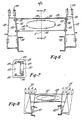
- Figure 3 further illustrates a Z-shaped plate 128 which provides a stabilizing means between the towers 54.
- the plate 128 has a stress relief hole 130 therein as best illustrated in Figures 6 and 7. Although the plate 128 stabilizes the towers 54 it allows enough freedom for flexure of the channels 58 on which the towers 54 are mounted under torsional stress, see Figure 3.
- the plate 128 has opposite hand end plates 132 welded to each end thereof with apertures 134 therein for receiving bolts for bolting the end plates 132 and thereby the plate 128 to the towers 54.
- the stress relief hole 130 in the plate 128 can be seen to be elongated with the upper and lower sides 136 and 138, forming its border, being longer than the sides 140 and 142 which complete the hole's border.
- a full cross-section of plate 128 exists adjacent the end plates 132 to act as a reinforcing stiffener because the stabilizing means is symmetrical about line C.
- the configuration of the hole 130 provides a lesser cross section of material at the top and bottom of the plate 128 where the line C intersects it to permit flexing of these portions when the channels 58 flex in torsion due to transverse deflection of the towers 54 under eccentric loading of the frame 12.
- the lips 144 and 146 in Figure 7 together with the above lesser cross section of the plate 128 form angle reinforcements uniform in cross section between the towers 54 to transfer loads therebetween and maintain the spacing between the towers 54 necessary for the desired operation of the loader 18 via the arms 48 and linkage 63 attached to the towers 54.
- the plate acts as an equalizer for forces on the towers 54.
- FIG 8 a schematic example is given of one type of tower deflection which may occur being exaggerated for purposes of illustration. Ncte the twisting of the channels 58 under the loading created by the force F in the direction indicated by the arrow.
- the force is a component resulting from eccentric loading on the frame 12 from, for example, use of one corner of the loader bucket 46 as described above.
- Another example would be deflection of the towers 54 relative to each other in the longitudinal direction of the channels 58 causing the plate 128 to twist.
- the lesser cross section and lips 144 and 146 forming the angle reinforcements would be able to twist in a manner similar to that illustrated in Figure 8 for the channels 58.
- the ability of a structural member to deflect prevents excessive stress on the plate 128 to tower 54 connection to avoid tearing the structure apart.
- the face plate 112 can be seen to be reinforced by inner and outer gusset plates 148 and 150 as well as a bottom gusset plate 152 as further illustrated in Figure 9.
- the bottom gusset plate 152 extends over the outer gusset plate 150 and to both the channel 58 and the face plate 112.
- the outer gusset plate 150 has three slotted apertures 154 for receiving alignment pins and the'inner gusset plate 148 can be seen to have a bend in it to permit the plate to extend from the outer portion of the channel 58 upper leg to the inner portion of its lower leg.
- the inner gusset plate 148 can be seen to have two legs 156 and 158 which extend towards the front of the frame 12 and are tapered in the direction of their extension.
- a gusseted angle member in Figure 9 is attached to the inner gusset plate 148 to provide a bracket 160 for supporting tractor components.
- FIG 10 a schematic example is given of-one type of channel deflection which occurs under torsional loading of the frame 12, being exaggerated for purposes of illustration. It can be seen that the twisting of the channels 58 causes deflection of the L-shaped ears 98 to prevent excessive stresses from arising and/or excessive loading of the axle housing 110.
- the channels 58 can be seen-to diverge from front (left) to rear (right) to accommodate the gauge of the front wheels 14 while providing as wide, and therefore. as stable, a connection as possible to receive the loading from the backhoe 20.
- the frame thus has a tapering configuration when viewed in plan.
- the rear ends of the channels 58 are fixed in spaced apart relation in a plane transverse to the longitudinal axis D of the tractor 10 and its frame 12 by means connecting the ends of the channels 58, such as the counterweight 118 or backhoe structure 40, to maintain the channels 58 in an outwardly diverging unbroken line from each other.
- the frames for supporting implements have either not taken advantage of a widened backhoe connection by maintaining the gauge of the front wheels, or where the gauge of the frame was changed the frame was fabricated with accommodating offsets or bent to achieve the same result.
- the bends or fabricated joints presented points for high stresses under loading and if torsional stress were allowed to twist the frame members as in the present application there would be likelihood of failure of the frame at these points.
- the frame 12 is assembled as follows. First a rail 58 and a tower 54 are secured in a jig to align these components in their correct relative positions, the bosses 60-64 being used for alignment purposes. The tower and rail are then welded together to form a first subassembly which also includes the bracket 92, 160, member 60, plate 112, pin 114 and ear 98. This process is then repeated to produce a second subassembly consisting of the rail and tower for the other side of the frame 12.
- the front ends of the rails 58 are then secured in a jig at the correct spacing and the rear ends of the rails are then canted outwardly, that is moved away from the longitudinal axis D of the frame to give the desired tapering frame shape.
- the rear ends of the rails are then held in their correct relative positions by a further jig which extends between the rear ends of the rails and uses the pins 114 for location.
- the plate 128 is then secured between the towers 54 and bolted up tight.
- the mounting plate 96 and axle saddle 56 are then secured firmly between the rails and the bolts securing the rails to the back axle are then tightened.
- the jigs extending between the front and rear ends of the rails can now be removed and the frame moved to the next assembly point on the line.
- the above frame 12 results in a lightweight rugged semi-integrated structure for carrying implements on a vehicle which can be stressed in both bending and torsion without adverse effect on the chassis of the vehicle to which the frame 12 is attached while at the same time providing sufficient connection to the chassis of the vehicle to obtain all the advantages of an integrated frame.
- the frame 12 optimizes the advantages of the lightweight of the attachable type loader frames while providing the strength and ruggedness approaching that of an integrated frame.
Landscapes
- Engineering & Computer Science (AREA)
- Mechanical Engineering (AREA)
- Chemical & Material Sciences (AREA)
- Structural Engineering (AREA)
- Combustion & Propulsion (AREA)
- Transportation (AREA)
- Architecture (AREA)
- Mining & Mineral Resources (AREA)
- Civil Engineering (AREA)
- General Engineering & Computer Science (AREA)
- Body Structure For Vehicles (AREA)
- Bending Of Plates, Rods, And Pipes (AREA)
- Automatic Cycles, And Cycles In General (AREA)
Applications Claiming Priority (2)
| Application Number | Priority Date | Filing Date | Title |
|---|---|---|---|
| US811407 | 1977-06-29 | ||
| US05/811,407 US4182456A (en) | 1977-06-29 | 1977-06-29 | Material handling machine |
Publications (2)
| Publication Number | Publication Date |
|---|---|
| EP0000281A1 true EP0000281A1 (fr) | 1979-01-10 |
| EP0000281B1 EP0000281B1 (fr) | 1981-09-23 |
Family
ID=25206465
Family Applications (1)
| Application Number | Title | Priority Date | Filing Date |
|---|---|---|---|
| EP78300094A Expired EP0000281B1 (fr) | 1977-06-29 | 1978-06-27 | Châssis-support d'outils de travail sur un véhicule et méthode de fabrication d'un tel châssis |
Country Status (7)
| Country | Link |
|---|---|
| US (1) | US4182456A (fr) |
| EP (1) | EP0000281B1 (fr) |
| BR (1) | BR7803879A (fr) |
| CA (1) | CA1091722A (fr) |
| DE (1) | DE2861111D1 (fr) |
| ES (1) | ES471241A1 (fr) |
| IT (1) | IT1158867B (fr) |
Cited By (8)
| Publication number | Priority date | Publication date | Assignee | Title |
|---|---|---|---|---|
| EP0158346A3 (en) * | 1984-04-13 | 1987-05-20 | Deere & Company | Frame element for a processing machine |
| FR2662569A1 (fr) * | 1990-06-02 | 1991-12-06 | Kubota Kk | Structure de chassis pour le montage d'un outil de travail, sur un tracteur, tel qu'un chargeur, faucheuse ou autres. |
| US5248237A (en) * | 1991-04-16 | 1993-09-28 | Kubota Corporation | Frame structure of a working vehicle for attaching a working implement |
| US9981687B2 (en) | 2016-02-17 | 2018-05-29 | Entro Industries, Inc. | Axle assembly |
| US9981520B2 (en) * | 2016-02-17 | 2018-05-29 | Entro Industries, Inc. | Removable axle assembly |
| US10407095B2 (en) | 2016-03-09 | 2019-09-10 | Entro Industries, Inc. | Detachable multi-axle assembly |
| EP3851587A1 (fr) * | 2020-01-20 | 2021-07-21 | J.C. Bamford Excavators Limited | Châssis de roulement pour un engin de travail |
| US20220227423A1 (en) * | 2021-01-20 | 2022-07-21 | J.C. Bamford Excavators Limited | Undercarriage |
Families Citing this family (25)
| Publication number | Priority date | Publication date | Assignee | Title |
|---|---|---|---|---|
| WO1998032928A1 (fr) * | 1997-01-28 | 1998-07-30 | Manitou Bf S.A. | Perfectionnement aux tracto-pelles |
| USD406151S (en) * | 1997-02-03 | 1999-02-23 | The Terramite Corporation | Compact loader backhoe |
| US6637136B2 (en) | 2001-07-10 | 2003-10-28 | Kuboto Corporation | Backhoe unit detachably attached to a tractor |
| US6729431B2 (en) * | 2001-07-10 | 2004-05-04 | Kubota Corporation | Tractor with implement mounting frame |
| USD529932S1 (en) * | 2004-09-03 | 2006-10-10 | Yanmar Co., Ltd | Tractor |
| JP4928087B2 (ja) * | 2005-03-14 | 2012-05-09 | ヤンマー株式会社 | 作業車両のフレーム構造 |
| USD540829S1 (en) * | 2006-03-14 | 2007-04-17 | Cnh America Llc | Tractor loader backhoe with tracks |
| USD540828S1 (en) * | 2006-03-14 | 2007-04-17 | Cnh America Llc | Tracked mini-excavator loader |
| JP4888739B2 (ja) * | 2006-11-24 | 2012-02-29 | 株式会社小松製作所 | ホイールローダ |
| JP5009933B2 (ja) * | 2006-12-08 | 2012-08-29 | 株式会社小松製作所 | ホイールローダ |
| JP2008201328A (ja) * | 2007-02-22 | 2008-09-04 | Kubota Corp | トラクタの後作業機装着フレーム構造。 |
| US7913798B2 (en) | 2008-03-07 | 2011-03-29 | Deere & Company | Armrest mounted grader control |
| USD629017S1 (en) * | 2009-09-17 | 2010-12-14 | J.C. Bamford Excavators Limited | Backhoe loader |
| USD628599S1 (en) * | 2009-09-17 | 2010-12-07 | J.C. Bamford Excavators Limited | Backhoe loader |
| JP5588207B2 (ja) * | 2010-03-24 | 2014-09-10 | 株式会社クボタ | トラクタ |
| CN102767203A (zh) * | 2012-06-29 | 2012-11-07 | 北京科实医学图像技术研究所 | 自平衡式挖掘机 |
| USD728631S1 (en) * | 2013-07-24 | 2015-05-05 | Cnh Industrial America Llc | Work vehicle |
| JP6576819B2 (ja) * | 2015-12-22 | 2019-09-18 | 株式会社神戸製鋼所 | 作業機械の旋回フレームの設計方法 |
| USD909423S1 (en) * | 2019-07-01 | 2021-02-02 | Jiangsu XCMG Construction Machinery Research Institute Co., Ltd | Backhoe loader |
| USD912101S1 (en) * | 2019-10-14 | 2021-03-02 | Clark Equipment Company | Backhoe loader |
| USD949207S1 (en) * | 2020-10-29 | 2022-04-19 | Jiangsu Xcmg Construction Machinery Research Institute Ltd. | Excavating and loading machine |
| US11199175B1 (en) | 2020-11-09 | 2021-12-14 | General Electric Company | Method and system for determining and tracking the top pivot point of a wind turbine tower |
| US11703033B2 (en) | 2021-04-13 | 2023-07-18 | General Electric Company | Method and system for determining yaw heading of a wind turbine |
| US11536250B1 (en) | 2021-08-16 | 2022-12-27 | General Electric Company | System and method for controlling a wind turbine |
| US12066010B2 (en) | 2022-04-04 | 2024-08-20 | Ge Infrastructure Technology Llc | Method and system for determining and tracking wind turbine tower deflection |
Citations (9)
| Publication number | Priority date | Publication date | Assignee | Title |
|---|---|---|---|---|
| GB405507A (en) * | 1932-05-19 | 1934-02-08 | Georges Broulhiet | Improvements in frames for vehicles |
| US2345351A (en) * | 1937-11-05 | 1944-03-28 | Deere & Co | Tractor |
| FR993712A (fr) * | 1949-08-24 | 1951-11-06 | Ametra G M B H | Châssis pour véhicules, notamment pour véhicules agricoles destinés à circuler en terrains accidentés, etc. |
| US2801863A (en) * | 1955-03-15 | 1957-08-06 | Int Harvester Co | Flexible frame construction for vehicle running gear |
| US3047170A (en) * | 1960-06-13 | 1962-07-31 | Hy Dynamic Co | Earth handling apparatus |
| GB1178387A (en) * | 1966-07-14 | 1970-01-21 | Midland Ind Computing | Improvements relating to Loader Arrangements for Agricultural Tractors or other Vehicles. |
| US3725996A (en) * | 1969-09-11 | 1973-04-10 | Int Harvester Co | Process of manufacturing first and second tractor vehicles for different work in the field |
| US3730545A (en) * | 1971-08-30 | 1973-05-01 | Int Harvester Co | Tractor weights |
| FR2291061A1 (fr) * | 1974-11-14 | 1976-06-11 | Hobbensiefken D | Vehicule a moteur monte a mi-longueur du chassis |
Family Cites Families (8)
| Publication number | Priority date | Publication date | Assignee | Title |
|---|---|---|---|---|
| US2598685A (en) * | 1950-11-02 | 1952-06-03 | Greenlief Jasper | Material handling machine |
| US2746624A (en) * | 1951-03-29 | 1956-05-22 | Deere & Co | Attachment frame for tractors |
| US2725995A (en) * | 1953-01-02 | 1955-12-06 | Elmer F Silbaugh | Front end loader with variable actuating arm |
| US2738083A (en) * | 1955-03-21 | 1956-03-13 | Vyrl E Cadwell | Quick attachable and detachable loader |
| US2931525A (en) * | 1956-10-15 | 1960-04-05 | Massey Ferguson Inc | Mounting apparatus for tractor attachments |
| US3022909A (en) * | 1957-11-29 | 1962-02-27 | Eddie T Y Gray | Agricultural machinery |
| US3207341A (en) * | 1963-01-10 | 1965-09-21 | Int Harvester Co | Loader |
| US3489303A (en) * | 1968-06-03 | 1970-01-13 | Deere & Co | Power loader |
-
1977
- 1977-06-29 US US05/811,407 patent/US4182456A/en not_active Expired - Lifetime
-
1978
- 1978-04-17 CA CA301,301A patent/CA1091722A/fr not_active Expired
- 1978-06-16 BR BR7803879A patent/BR7803879A/pt unknown
- 1978-06-27 DE DE7878300094T patent/DE2861111D1/de not_active Expired
- 1978-06-27 EP EP78300094A patent/EP0000281B1/fr not_active Expired
- 1978-06-28 ES ES471241A patent/ES471241A1/es not_active Expired
- 1978-06-28 IT IT25086/78A patent/IT1158867B/it active
Patent Citations (9)
| Publication number | Priority date | Publication date | Assignee | Title |
|---|---|---|---|---|
| GB405507A (en) * | 1932-05-19 | 1934-02-08 | Georges Broulhiet | Improvements in frames for vehicles |
| US2345351A (en) * | 1937-11-05 | 1944-03-28 | Deere & Co | Tractor |
| FR993712A (fr) * | 1949-08-24 | 1951-11-06 | Ametra G M B H | Châssis pour véhicules, notamment pour véhicules agricoles destinés à circuler en terrains accidentés, etc. |
| US2801863A (en) * | 1955-03-15 | 1957-08-06 | Int Harvester Co | Flexible frame construction for vehicle running gear |
| US3047170A (en) * | 1960-06-13 | 1962-07-31 | Hy Dynamic Co | Earth handling apparatus |
| GB1178387A (en) * | 1966-07-14 | 1970-01-21 | Midland Ind Computing | Improvements relating to Loader Arrangements for Agricultural Tractors or other Vehicles. |
| US3725996A (en) * | 1969-09-11 | 1973-04-10 | Int Harvester Co | Process of manufacturing first and second tractor vehicles for different work in the field |
| US3730545A (en) * | 1971-08-30 | 1973-05-01 | Int Harvester Co | Tractor weights |
| FR2291061A1 (fr) * | 1974-11-14 | 1976-06-11 | Hobbensiefken D | Vehicule a moteur monte a mi-longueur du chassis |
Cited By (11)
| Publication number | Priority date | Publication date | Assignee | Title |
|---|---|---|---|---|
| EP0158346A3 (en) * | 1984-04-13 | 1987-05-20 | Deere & Company | Frame element for a processing machine |
| FR2662569A1 (fr) * | 1990-06-02 | 1991-12-06 | Kubota Kk | Structure de chassis pour le montage d'un outil de travail, sur un tracteur, tel qu'un chargeur, faucheuse ou autres. |
| US5123805A (en) * | 1990-06-02 | 1992-06-23 | Kubota Corporation | Frame structure for attaching a working implement |
| US5248237A (en) * | 1991-04-16 | 1993-09-28 | Kubota Corporation | Frame structure of a working vehicle for attaching a working implement |
| US9981687B2 (en) | 2016-02-17 | 2018-05-29 | Entro Industries, Inc. | Axle assembly |
| US9981520B2 (en) * | 2016-02-17 | 2018-05-29 | Entro Industries, Inc. | Removable axle assembly |
| US10407095B2 (en) | 2016-03-09 | 2019-09-10 | Entro Industries, Inc. | Detachable multi-axle assembly |
| EP3851587A1 (fr) * | 2020-01-20 | 2021-07-21 | J.C. Bamford Excavators Limited | Châssis de roulement pour un engin de travail |
| GB2591143B (en) * | 2020-01-20 | 2023-11-08 | Bamford Excavators Ltd | An undercarriage |
| US20220227423A1 (en) * | 2021-01-20 | 2022-07-21 | J.C. Bamford Excavators Limited | Undercarriage |
| US11459034B2 (en) | 2021-01-20 | 2022-10-04 | J.C. Bamford Excavators Limited | Undercarriage |
Also Published As
| Publication number | Publication date |
|---|---|
| IT1158867B (it) | 1987-02-25 |
| DE2861111D1 (en) | 1981-12-10 |
| US4182456A (en) | 1980-01-08 |
| ES471241A1 (es) | 1980-12-01 |
| BR7803879A (pt) | 1979-01-09 |
| CA1091722A (fr) | 1980-12-16 |
| IT7825086A0 (it) | 1978-06-28 |
| EP0000281B1 (fr) | 1981-09-23 |
Similar Documents
| Publication | Publication Date | Title |
|---|---|---|
| EP0000281B1 (fr) | Châssis-support d'outils de travail sur un véhicule et méthode de fabrication d'un tel châssis | |
| US6729431B2 (en) | Tractor with implement mounting frame | |
| US4151920A (en) | Vehicle main frame | |
| KR20130124168A (ko) | 건설기계 | |
| US4904151A (en) | Loader lift arm structure | |
| US4807461A (en) | Motor grader main frame | |
| US4162872A (en) | Lift arm assembly | |
| US4220215A (en) | A-frame for carrying loads on a loader | |
| US4696350A (en) | Motor grader with saddle mounted to transverse pin on main frame | |
| US6158525A (en) | Main frame structure and steering case of construction equipment | |
| JP2001342646A (ja) | 建設機械の旋回フレーム | |
| US4186812A (en) | Equalizer bar support assembly | |
| US8387714B2 (en) | Rear implement mounting frame construction for tractor | |
| US3527474A (en) | Pivotally mounted tractor roll bar | |
| JP2003129522A (ja) | 建設機械の旋回フレーム | |
| JP3917448B2 (ja) | トラクタのフロントガード装置 | |
| JP2519829Y2 (ja) | 建設機械のジャッキアップ装置の取付け構造 | |
| CN218907433U (zh) | 履带架和履带式工程机械 | |
| JP3530375B2 (ja) | フロントローダ | |
| EP0005907A1 (fr) | Châssis de tracteur avec longerons profilés en U | |
| JP2978894B1 (ja) | 建設機械のメインフレーム構造 | |
| JP3947024B2 (ja) | ローダ作業機 | |
| JP3474768B2 (ja) | フロントローダ | |
| CN217811319U (zh) | 一种工程机械框架及工程机械 | |
| CN117738259B (zh) | 一种平地机前机架及平地机 |
Legal Events
| Date | Code | Title | Description |
|---|---|---|---|
| PUAI | Public reference made under article 153(3) epc to a published international application that has entered the european phase |
Free format text: ORIGINAL CODE: 0009012 |
|
| AK | Designated contracting states |
Designated state(s): DE FR GB |
|
| 17P | Request for examination filed | ||
| GRAA | (expected) grant |
Free format text: ORIGINAL CODE: 0009210 |
|
| AK | Designated contracting states |
Designated state(s): DE FR GB |
|
| REF | Corresponds to: |
Ref document number: 2861111 Country of ref document: DE Date of ref document: 19811210 |
|
| PGFP | Annual fee paid to national office [announced via postgrant information from national office to epo] |
Ref country code: FR Payment date: 19840629 Year of fee payment: 7 |
|
| PGFP | Annual fee paid to national office [announced via postgrant information from national office to epo] |
Ref country code: DE Payment date: 19840801 Year of fee payment: 7 |
|
| PG25 | Lapsed in a contracting state [announced via postgrant information from national office to epo] |
Ref country code: FR Free format text: LAPSE BECAUSE OF NON-PAYMENT OF DUE FEES Effective date: 19880226 |
|
| PG25 | Lapsed in a contracting state [announced via postgrant information from national office to epo] |
Ref country code: DE Effective date: 19880301 |
|
| GBPC | Gb: european patent ceased through non-payment of renewal fee | ||
| REG | Reference to a national code |
Ref country code: FR Ref legal event code: ST |
|
| PG25 | Lapsed in a contracting state [announced via postgrant information from national office to epo] |
Ref country code: GB Effective date: 19881117 |
|
| PLBE | No opposition filed within time limit |
Free format text: ORIGINAL CODE: 0009261 |
|
| STAA | Information on the status of an ep patent application or granted ep patent |
Free format text: STATUS: NO OPPOSITION FILED WITHIN TIME LIMIT |