EP0000340A1 - Dispositif pour la fixation de plis de rideaux - Google Patents
Dispositif pour la fixation de plis de rideaux Download PDFInfo
- Publication number
- EP0000340A1 EP0000340A1 EP78100215A EP78100215A EP0000340A1 EP 0000340 A1 EP0000340 A1 EP 0000340A1 EP 78100215 A EP78100215 A EP 78100215A EP 78100215 A EP78100215 A EP 78100215A EP 0000340 A1 EP0000340 A1 EP 0000340A1
- Authority
- EP
- European Patent Office
- Prior art keywords
- support plate
- fold
- webs
- folds
- clamp
- Prior art date
- Legal status (The legal status is an assumption and is not a legal conclusion. Google has not performed a legal analysis and makes no representation as to the accuracy of the status listed.)
- Granted
Links
- XLYOFNOQVPJJNP-UHFFFAOYSA-N water Substances O XLYOFNOQVPJJNP-UHFFFAOYSA-N 0.000 claims 1
- 239000004744 fabric Substances 0.000 description 14
- 210000000078 claw Anatomy 0.000 description 7
- 230000037431 insertion Effects 0.000 description 3
- 238000003780 insertion Methods 0.000 description 3
- 230000007704 transition Effects 0.000 description 3
- 206010040954 Skin wrinkling Diseases 0.000 description 2
- 239000000463 material Substances 0.000 description 2
- 239000004033 plastic Substances 0.000 description 2
- 239000004952 Polyamide Substances 0.000 description 1
- 239000003513 alkali Substances 0.000 description 1
- 239000002585 base Substances 0.000 description 1
- 238000005452 bending Methods 0.000 description 1
- 230000015572 biosynthetic process Effects 0.000 description 1
- 238000010276 construction Methods 0.000 description 1
- 229920002647 polyamide Polymers 0.000 description 1
- 125000006850 spacer group Chemical group 0.000 description 1
- 239000000725 suspension Substances 0.000 description 1
- 229920001169 thermoplastic Polymers 0.000 description 1
- 239000004416 thermosoftening plastic Substances 0.000 description 1
- 238000005406 washing Methods 0.000 description 1
- 230000037303 wrinkles Effects 0.000 description 1
Images


Classifications
-
- A—HUMAN NECESSITIES
- A47—FURNITURE; DOMESTIC ARTICLES OR APPLIANCES; COFFEE MILLS; SPICE MILLS; SUCTION CLEANERS IN GENERAL
- A47H—FURNISHINGS FOR WINDOWS OR DOORS
- A47H13/00—Fastening curtains on curtain rods or rails
- A47H13/14—Means for forming pleats
-
- Y—GENERAL TAGGING OF NEW TECHNOLOGICAL DEVELOPMENTS; GENERAL TAGGING OF CROSS-SECTIONAL TECHNOLOGIES SPANNING OVER SEVERAL SECTIONS OF THE IPC; TECHNICAL SUBJECTS COVERED BY FORMER USPC CROSS-REFERENCE ART COLLECTIONS [XRACs] AND DIGESTS
- Y10—TECHNICAL SUBJECTS COVERED BY FORMER USPC
- Y10T—TECHNICAL SUBJECTS COVERED BY FORMER US CLASSIFICATION
- Y10T24/00—Buckles, buttons, clasps, etc.
- Y10T24/34—Combined diverse multipart fasteners
- Y10T24/3427—Clasp
- Y10T24/3449—Clasp and hook
- Y10T24/3451—Clasp and hook having intermediate connector allowing movement
- Y10T24/3452—Clasp and hook having intermediate connector allowing movement and adjustment means
Definitions
- the invention relates to a device for fixing folds on curtains and curtains, with vertically extending webs which are open at the top and bottom, an inserted fold being held in an elastically clamping manner in a slot formed between two webs and projecting into the respective slot on the webs barb-like projections are arranged.
- Such a device known from DT-PS 22 27 199 (corresponding to US-PS 3 861 00 1) is formed in one piece.
- This known device has the general advantage that it is relatively simple due to its one-piece construction. Their disadvantage is that the folds are only held on their feet.
- This known device is that the formation of a so-called head on the curtain, i. H. it is not possible to form a part on the curtain that goes upward beyond the holding device. Furthermore, this known device is not suitable for holding more sensitive curtain fabrics, since, due to the punctiform mounting on the barbs of the claws, there is a risk of tearing the fabric when subjected to a load. In addition, the front finger-like claws are visible when a forward protruding fold is formed, which is aesthetically disturbing.
- a holding device for curtains is known in which a hook can be fastened to a holding device by means of pins projecting from a plate of the hook with spherical heads which can be inserted into corresponding openings in the holding body.
- the invention has for its object to provide a device of the type described above, by means of which protruding folds are held securely and precisely fixed in their shape without the folds becoming completely rigid in themselves in the fixing area.
- an elastic fold clamp which can be locked with a support plate
- This configuration according to the invention makes it possible, on the one hand, to hold folds to be fixed in the widely projecting fold clamping device, which extends only over a small area of the total height of the device, in such a way that they are fixed over their full depth.
- the other fold clamping device on the other hand, only the foot is held by one or more folds, so that the folds can already spring open again without changing their position relative to the device.
- a double layer of fabric is firmly fixed between the fold clip and the support plate, whereby at the same time the respective outer layer of the outer folds is precisely fixed.
- the curtain or the curtain itself is carried by the device.
- the entire device is located on the back of the curtain and is therefore not recognizable from its visible side.
- the fold clip advantageously has an approximately cylindrical segment-shaped cross section. According to a particularly advantageous embodiment, it is provided that at least one pair of elastic webs with protruding outwards on the inside of the fold clip jumps are provided with stop surfaces and that associated locking openings are provided on the support plate with contact surfaces for the stop surfaces.
- a hook which has at least one row with at least two projecting pins which can be inserted into corresponding openings in the support plate.
- the hook has a bracket attached to a plate, the free end of which can be connected to the plate in the manner of a safety pin.
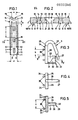
- the device shown in the drawing consists of a support plate 1, on the front of which a folding clip 2 and on the rear of which a hook 3 can each be detachably attached.
- the support plate 1 has a flat, elongated, rectangular shape. On its front side 4 it is provided with tooth-like projections 5, of which a row is provided in the vicinity of the associated side edge 6 and 7, respectively. These rows of tooth-like projections 5 run parallel to one another and to the center line 8 of the support plate 1.
- the tooth-like projections 5 have the shape of a triangular pyramid, one side surface 9 of which faces away from the associated side edge 6 and 7, projects vertically from the front side 4 of the support plate while the other two side surfaces 1 0 , 11 run flat inclined towards the outer edge.
- a row of openings 12 are again provided parallel to the center line 8 and on both sides at the same distance from it.
- These consist of a cylindrical section 13 lying towards the front side 4 of the support plate 1, a cylindrical section 14 of smaller diameter adjoining it, located inside the support plate 1, and a frustoconical section 16 which widens towards the rear side 15 of the support plate 1.
- an annular contact shoulder 17 directed towards the front side 4 is formed.
- each locking openings 18 likewise extending through the support plate 1 from its front side 4 to its rear side 15, of approximately rectangular cross section in plan view. They consist of a narrowest rectangular section 19 lying in the interior of the support plate 1, on the vertical side surfaces 2o of which insertion surfaces 21 adjoin one another at a distance from the front side 4. The side surfaces 20 of the section 19 spring back towards the rear side 15, forming contact surfaces 22 which are open towards the rear side 15, so that an enlarged section 23 is formed here.
- a hook 3 has a plate 24, from the top 25 of which a bracket 26 is attached bent backwards and downwards.
- the bracket 26 is provided with a tapered section 27 in the region of its free end.
- an upwardly open catch 29 is attached to the latter, one side wall 30 of which is provided with a recess 31 in the region of the rear side 28 of the plate 24.
- Attached to the front 34 of the plate 24 are two rows of vertically projecting pins 35, each having a spherical head 36 at its end.
- the two rows of pins 35 with heads 36 are at the same distance a from one another that the two rows of openings 12 have in the support plate 1.
- the distance b between two adjacent pins 35 with heads 36 in a row is the same as the distance between two adjacent openings 12 in the support plate 1.
- the diameter of the pin 35 is slightly smaller than the diameter of the narrow cylindrical sections 14 in the support plate.
- the diameter of the spherical heads 36 is somewhat larger than the diameter of the narrower cylindrical sections 14 and somewhat smaller than the diameter of the further cylindrical sections 13.
- the heads 36 When a connection is made between the hook 3 and a support plate 1, the heads 36 become into the frustoconical sections 16 pressed in, causing the heads to deform slightly elastically so that they can be pushed through the narrower sections 14. In the other cylindrical sections 13, they spring back up elastically and lie behind the contact shoulders 17, as a result of which a very firm but, with the greatest effort, detachable connection between the hook 3 and the support plate 1 is produced. Since a relatively large number of openings 12 are provided on the support plate 1 in each row, the hook 3 can be very difficult different heights are attached to the support plate 1.
- the folding clip 2 has an elongated, elastically deformable clip part 37, approximately rectangular in plan view, which - in cross section - has approximately the shape of a ring cylinder segment.
- the fold clip 2 is constructed symmetrically to a plane of symmetry 38.
- the three pairs of webs 4 0, 41 are at the same distance c attached to each other as the locking apertures 18 in the support plate 1.
- the length of the webs 4o, 41 is slightly smaller than the length of the locking openings 18.
- a series of tooth-like projections 49 is attached, which are identical to the projections 5.
- the distance d between the two rows of projections is the same as in the case of the support plate 1.
- the individual projections 49 are only arranged such that they come between two adjacent projections 5 of the support plate 1 when the fold clamp 2 is locked with the support plate 1. In particular, these projections 49 thus have mutually facing side surfaces 5 0 lying parallel to the plane of symmetry 38.
- the length of the webs 4ö, 41 on the one hand and the curvature of the clamp part 37 is selected such that when the fold clamp 2 is locked with the support plate 1, some air is still left between the respective tips of the projections 5 and 49 and the associated front side 4 of the support plate 1 and the longitudinal edges. 47, -48 of the folding clip 2.
- two fold clamping devices 52, 53 are attached at a distance from one another. These in turn consist of two spaced apart webs 54 and 55, which are provided in the region of their free ends with tooth-like projections 56, 57 directed towards each other. These tooth-like projections 56, 57 have on their outer side inclined insertion surfaces 58, 59 towards the front side 51 of the clamp part and on their side lying towards the front side 51 approximately perpendicular to the plane of symmetry 38 side surfaces 6 0 and 61; the tooth-like projections 56, 57 are thus designed like barbs.
- the webs of the fold clamping device 52 protrude much more from the front side 51 than the webs 55 of the fold clamping device 53.
- the middle fold foot 68 is pushed between the webs 55 of the smaller upper fold clamping device 53, where it is then likewise secured against being pulled out.
- the middle fold foot 68 is pushed between the webs 55 of the smaller upper fold clamping device 53, where it is then likewise secured against being pulled out.
- the pleated clip 2 is locked in the manner already described with the support plate 1, the two double fabric layers 7 0 , 71, each forming an outer pleated foot, being firmly secured between the support plate and the pleated clip against being pulled out.
- the support plate 1, the folding clip 2 and the hook 3 are each made in one piece from a hard elastic thermoplastic.
- the hook 3 can be attached to the support plate 1 at any height, as described. Then the entire curtain or the curtain 62 is securely but releasably attached to a curtain rail according to the so-called American system by means of the hook.
- the support plate 1, folding clip 2 and the hook 3 are expediently made of alkali and light-stable plastic, such as. B. made of a polyamide.
- alkali and light-stable plastic such as. B. made of a polyamide.
- a knitted or woven stiffening band 77 is always processed at the same time when folding, which is shown in FIG. 12 only in the side Areas are shown so as not to disturb the clarity of the drawing. It lies close to the back of the fabric, so it also extends along the folds 63 to 66 on the inside thereof.
- Such a stiffening band 77 will generally be so wide that it extends from the upper edge of the curtain to below the lower pleat clamping device 52.
- a curtain is simply a lining material attached to the back of it. As a rule, such a stiffening tape will be sewn onto the curtain or the curtain 62.
Landscapes
- Curtains And Furnishings For Windows Or Doors (AREA)
- Warehouses Or Storage Devices (AREA)
Applications Claiming Priority (2)
| Application Number | Priority Date | Filing Date | Title |
|---|---|---|---|
| DE2732242A DE2732242C2 (de) | 1977-07-16 | 1977-07-16 | Vorrichtung zur Fixierung von Falten an Gardinen und Vorhängen |
| DE2732242 | 1977-07-16 |
Publications (2)
| Publication Number | Publication Date |
|---|---|
| EP0000340A1 true EP0000340A1 (fr) | 1979-01-24 |
| EP0000340B1 EP0000340B1 (fr) | 1980-07-23 |
Family
ID=6014106
Family Applications (1)
| Application Number | Title | Priority Date | Filing Date |
|---|---|---|---|
| EP78100215A Expired EP0000340B1 (fr) | 1977-07-16 | 1978-06-22 | Dispositif pour la fixation de plis de rideaux |
Country Status (6)
| Country | Link |
|---|---|
| US (1) | US4166308A (fr) |
| EP (1) | EP0000340B1 (fr) |
| AT (1) | AT367627B (fr) |
| DE (1) | DE2732242C2 (fr) |
| DK (1) | DK281878A (fr) |
| NO (1) | NO782287L (fr) |
Families Citing this family (7)
| Publication number | Priority date | Publication date | Assignee | Title |
|---|---|---|---|---|
| US4277865A (en) * | 1978-06-14 | 1981-07-14 | Ietsugu Takazawa | Curtain hanger |
| US4261080A (en) * | 1979-09-10 | 1981-04-14 | Ryan Richard B | Adjustable drapery support assembly |
| US4344210A (en) * | 1979-09-10 | 1982-08-17 | Ryan Richard B | Adjustable drapery support assembly |
| USD292370S (en) | 1985-02-15 | 1987-10-20 | Custom Shade & Awning Corp. | Bracket for shaping curtains and similar articles |
| US20100125987A1 (en) * | 2008-11-27 | 2010-05-27 | Ted Barkun | Curtain carrier for draping a curtain from a curtain rod |
| JP3161739U (ja) * | 2010-05-28 | 2010-08-05 | 株式会社東京ソーイングカーテン | カーテン吊下具 |
| US10398248B1 (en) * | 2016-08-11 | 2019-09-03 | Ivan Curtis Burch, Jr. | Adjustable drapery form structure |
Citations (9)
| Publication number | Priority date | Publication date | Assignee | Title |
|---|---|---|---|---|
| BE530471A (fr) * | ||||
| FR1203911A (fr) * | 1958-07-29 | 1960-01-21 | Agrafe pour l'obtention de plis sur les rideaux et tentures et son mode d'utilisation | |
| US3325853A (en) * | 1963-09-04 | 1967-06-20 | Stroweis Jerome | Suspension device for curtains |
| CH481618A (de) * | 1967-12-30 | 1969-11-30 | Hachtel Wilhelm | Einrichtung zum Faltenbilden an Vorhängen |
| DE1958717A1 (de) * | 1968-12-09 | 1970-07-16 | Concept S A | Vorrichtung zum Aufhaengen von Gardinen,Vorhaengen u.dgl. unter Faltenbildung |
| CH567394A5 (fr) * | 1974-08-15 | 1975-10-15 | Maron & Co Ag | |
| US3992749A (en) * | 1975-07-21 | 1976-11-23 | Getchell F Grant | Drapery slide and adjustable clip combination |
| DE2065908A1 (de) * | 1970-05-15 | 1976-12-16 | Hugo Bier | Sicherheitsnadelfoermiger aufhaenger |
| DE2550786A1 (de) * | 1975-11-12 | 1977-05-26 | Gardisette Holding | Gardine bzw. vorhang mit am oberen rand angeordneten und fixierten doppelfalten |
Family Cites Families (7)
| Publication number | Priority date | Publication date | Assignee | Title |
|---|---|---|---|---|
| US2552922A (en) * | 1948-09-27 | 1951-05-15 | Rubie E Andreou | Pleater hook for drapes |
| US2765844A (en) * | 1955-12-09 | 1956-10-09 | Virginia R Kuddes | Apparatus for hanging draperies |
| US3399712A (en) * | 1966-03-10 | 1968-09-03 | Worthy Products Corp | Drapery pleat forming and supporting assembly |
| US3735795A (en) * | 1970-11-12 | 1973-05-29 | Plastofold Ag | Support for suspending a curtain |
| AT321489B (de) * | 1972-06-03 | 1975-04-10 | Gardisette Holding | Einrichtung zur Fixierung von Falten an Gardinen und Vorhängen |
| US3921696A (en) * | 1972-11-11 | 1975-11-25 | Gardisette Holding | Fittings for gathering and fixing curtains or drapes |
| US3901303A (en) * | 1974-04-25 | 1975-08-26 | Douglas Manufacturing Co Inc | Drapery holder |
-
1977
- 1977-07-16 DE DE2732242A patent/DE2732242C2/de not_active Expired
- 1977-10-17 US US05/843,042 patent/US4166308A/en not_active Expired - Lifetime
-
1978
- 1978-06-22 EP EP78100215A patent/EP0000340B1/fr not_active Expired
- 1978-06-22 DK DK782818A patent/DK281878A/da not_active Application Discontinuation
- 1978-06-26 AT AT0461178A patent/AT367627B/de not_active IP Right Cessation
- 1978-06-30 NO NO782287A patent/NO782287L/no unknown
Patent Citations (9)
| Publication number | Priority date | Publication date | Assignee | Title |
|---|---|---|---|---|
| BE530471A (fr) * | ||||
| FR1203911A (fr) * | 1958-07-29 | 1960-01-21 | Agrafe pour l'obtention de plis sur les rideaux et tentures et son mode d'utilisation | |
| US3325853A (en) * | 1963-09-04 | 1967-06-20 | Stroweis Jerome | Suspension device for curtains |
| CH481618A (de) * | 1967-12-30 | 1969-11-30 | Hachtel Wilhelm | Einrichtung zum Faltenbilden an Vorhängen |
| DE1958717A1 (de) * | 1968-12-09 | 1970-07-16 | Concept S A | Vorrichtung zum Aufhaengen von Gardinen,Vorhaengen u.dgl. unter Faltenbildung |
| DE2065908A1 (de) * | 1970-05-15 | 1976-12-16 | Hugo Bier | Sicherheitsnadelfoermiger aufhaenger |
| CH567394A5 (fr) * | 1974-08-15 | 1975-10-15 | Maron & Co Ag | |
| US3992749A (en) * | 1975-07-21 | 1976-11-23 | Getchell F Grant | Drapery slide and adjustable clip combination |
| DE2550786A1 (de) * | 1975-11-12 | 1977-05-26 | Gardisette Holding | Gardine bzw. vorhang mit am oberen rand angeordneten und fixierten doppelfalten |
Also Published As
| Publication number | Publication date |
|---|---|
| AT367627B (de) | 1982-07-26 |
| DE2732242C2 (de) | 1979-08-30 |
| ATA461178A (de) | 1981-12-15 |
| NO782287L (no) | 1979-01-17 |
| DE2732242B1 (de) | 1979-01-11 |
| DK281878A (da) | 1979-01-17 |
| EP0000340B1 (fr) | 1980-07-23 |
| US4166308A (en) | 1979-09-04 |
Similar Documents
| Publication | Publication Date | Title |
|---|---|---|
| DE69714419T2 (de) | Verbesserung an jalousien | |
| EP0110811B1 (fr) | Ruban pour tête de rideau | |
| DE3915461C2 (de) | Vorhanggleiter | |
| CH672980A5 (fr) | ||
| DE1921295A1 (de) | Aufhaengevorrichtung fuer Vorhaenge,insbesondere Faltenvorhaenge | |
| EP0000340B1 (fr) | Dispositif pour la fixation de plis de rideaux | |
| DE2139863C3 (de) | Bausatz zur Herstellung von ganz oder teilweise eingefaßten Texten | |
| DE3004040C2 (de) | Aufhängevorrichtung zum Trocknen von Kleidungsstücken | |
| DE3878175T2 (de) | Verbindungsteil. | |
| DE2107224C3 (de) | Vorhang-Innengleiter aus thermoplastischem Kunststoff | |
| DE3038022C2 (de) | Aufhängbare Rasterdecke | |
| DE2227199C2 (de) | Einrichtung zur Fixierung von Falten an Gardinen und Vorhängen | |
| DE2255328C2 (de) | Vorrichtung zum Raffen und Fixieren von aufzuhängendem Gardinen- bzw. Vorhangstoff | |
| DE9319047U1 (de) | Gardine | |
| DE2258213C3 (de) | Befestigungsklammer für Leisten mit T-förmiger Aussparung zur Anbringung an Wänden mit Durchtrittslöchern | |
| DE2550786A1 (de) | Gardine bzw. vorhang mit am oberen rand angeordneten und fixierten doppelfalten | |
| DE2227199B1 (de) | Einrichtung zur fixierung von falten an gardinen und vorhaengen | |
| DE2050237A1 (de) | Vorrichtung zum gefalteten Auf hangen einei Gardine | |
| DE9203861U1 (de) | Gardine | |
| DE2328291C3 (de) | Einrichtung zum Halten von Gardinen und Vorhängen | |
| DE866993C (de) | Akten-Registriereinrichtung | |
| EP0049433A2 (fr) | Faux-plafond à résilles | |
| DE1429746C (de) | Aufhängevorrichtung, insbesondere für Handtücher od.dgl | |
| DE2240793C3 (de) | Vorrichtung zum Aufhängen und Raffen eines auf- und zuziehbaren Vorhangs aus flexiblem Material | |
| CH650731A5 (en) | Array element |
Legal Events
| Date | Code | Title | Description |
|---|---|---|---|
| PUAI | Public reference made under article 153(3) epc to a published international application that has entered the european phase |
Free format text: ORIGINAL CODE: 0009012 |
|
| AK | Designated contracting states |
Designated state(s): BE CH FR GB NL SE |
|
| 17P | Request for examination filed | ||
| GRAA | (expected) grant |
Free format text: ORIGINAL CODE: 0009210 |
|
| AK | Designated contracting states |
Designated state(s): BE CH FR GB NL SE |
|
| PGFP | Annual fee paid to national office [announced via postgrant information from national office to epo] |
Ref country code: SE Payment date: 19810531 Year of fee payment: 4 |
|
| PGFP | Annual fee paid to national office [announced via postgrant information from national office to epo] |
Ref country code: NL Payment date: 19810630 Year of fee payment: 4 Ref country code: CH Payment date: 19810630 Year of fee payment: 4 Ref country code: BE Payment date: 19810630 Year of fee payment: 4 |
|
| PGFP | Annual fee paid to national office [announced via postgrant information from national office to epo] |
Ref country code: FR Payment date: 19810701 Year of fee payment: 4 |
|
| PG25 | Lapsed in a contracting state [announced via postgrant information from national office to epo] |
Ref country code: BE Effective date: 19820622 |
|
| PG25 | Lapsed in a contracting state [announced via postgrant information from national office to epo] |
Ref country code: SE Effective date: 19820623 |
|
| PG25 | Lapsed in a contracting state [announced via postgrant information from national office to epo] |
Ref country code: CH Effective date: 19820630 |
|
| PG25 | Lapsed in a contracting state [announced via postgrant information from national office to epo] |
Ref country code: NL Effective date: 19830101 |
|
| NLV4 | Nl: lapsed or anulled due to non-payment of the annual fee | ||
| REG | Reference to a national code |
Ref country code: CH Ref legal event code: PL |
|
| GBPC | Gb: european patent ceased through non-payment of renewal fee | ||
| PG25 | Lapsed in a contracting state [announced via postgrant information from national office to epo] |
Ref country code: FR Free format text: LAPSE BECAUSE OF NON-PAYMENT OF DUE FEES Effective date: 19830331 |
|
| REG | Reference to a national code |
Ref country code: FR Ref legal event code: ST |
|
| PG25 | Lapsed in a contracting state [announced via postgrant information from national office to epo] |
Ref country code: GB Effective date: 19881117 |
|
| ITCP | It: supplementary protection certificate |
Spc suppl protection certif: CCP 48 |
|
| EUG | Se: european patent has lapsed |
Ref document number: 78100215.9 Effective date: 19850612 |
|
| PLBE | No opposition filed within time limit |
Free format text: ORIGINAL CODE: 0009261 |
|
| STAA | Information on the status of an ep patent application or granted ep patent |
Free format text: STATUS: NO OPPOSITION FILED WITHIN TIME LIMIT |