EP0000708A1 - Dispositif d'empilage d'objets en forme de baguettes ou de planches - Google Patents
Dispositif d'empilage d'objets en forme de baguettes ou de planches Download PDFInfo
- Publication number
- EP0000708A1 EP0000708A1 EP7878100409A EP78100409A EP0000708A1 EP 0000708 A1 EP0000708 A1 EP 0000708A1 EP 7878100409 A EP7878100409 A EP 7878100409A EP 78100409 A EP78100409 A EP 78100409A EP 0000708 A1 EP0000708 A1 EP 0000708A1
- Authority
- EP
- European Patent Office
- Prior art keywords
- stacking
- support arms
- stand
- storage surface
- stacking device
- Prior art date
- Legal status (The legal status is an assumption and is not a legal conclusion. Google has not performed a legal analysis and makes no representation as to the accuracy of the status listed.)
- Granted
Links
- 230000001419 dependent effect Effects 0.000 abstract description 2
- 238000010586 diagram Methods 0.000 description 2
- 230000015572 biosynthetic process Effects 0.000 description 1
- 238000000151 deposition Methods 0.000 description 1
- 230000014759 maintenance of location Effects 0.000 description 1
- 238000004519 manufacturing process Methods 0.000 description 1
Images


Classifications
-
- B—PERFORMING OPERATIONS; TRANSPORTING
- B65—CONVEYING; PACKING; STORING; HANDLING THIN OR FILAMENTARY MATERIAL
- B65G—TRANSPORT OR STORAGE DEVICES, e.g. CONVEYORS FOR LOADING OR TIPPING, SHOP CONVEYOR SYSTEMS OR PNEUMATIC TUBE CONVEYORS
- B65G57/00—Stacking of articles
- B65G57/02—Stacking of articles by adding to the top of the stack
- B65G57/16—Stacking of articles of particular shape
- B65G57/18—Stacking of articles of particular shape elongated, e.g. sticks, rods, bars
-
- Y—GENERAL TAGGING OF NEW TECHNOLOGICAL DEVELOPMENTS; GENERAL TAGGING OF CROSS-SECTIONAL TECHNOLOGIES SPANNING OVER SEVERAL SECTIONS OF THE IPC; TECHNICAL SUBJECTS COVERED BY FORMER USPC CROSS-REFERENCE ART COLLECTIONS [XRACs] AND DIGESTS
- Y10—TECHNICAL SUBJECTS COVERED BY FORMER USPC
- Y10S—TECHNICAL SUBJECTS COVERED BY FORMER USPC CROSS-REFERENCE ART COLLECTIONS [XRACs] AND DIGESTS
- Y10S414/00—Material or article handling
- Y10S414/10—Associated with forming or dispersing groups of intersupporting articles, e.g. stacking patterns
- Y10S414/115—Associated with forming or dispersing groups of intersupporting articles, e.g. stacking patterns including article counter
Definitions
- the invention relates to a stacking device for rod-shaped or board-shaped piece goods, with vertically movable stacking trolleys on stands with horizontally movable support arms and with fixed stops, parallel, circumferential drivers which receive the piece goods on the back of the stand and on one on the top of the Place the shelf on the stand.
- Stacking devices of this type are from the German patents 1 191 296, 1 235 808, 2 445 536 and 2 553 724.
- the piece goods transported vertically upwards by a carrier on the back of the stands are individually deposited on the storage surface located on the top of the stands and taken away by the following driver by means of its fixed stop for further transport.
- the general cargo is transported on the front of the stand.
- the individual piece goods are conveyed downwards until they are placed on the extended support arms of the stacking trolleys and individually moved onto them to form a stacking row.
- the support arms are moved back and the stacking trolleys are moved vertically by the height of one row of stacks, whereupon the support arms are extended again to form the next row of stacks.
- the stands have to be built relatively high so that the piece goods can be guided over magazines for intermediate strips, which are optionally attached directly to the stacking trolley and can be moved vertically with them.
- the invention is based on the object of creating a stacking device of the type mentioned at the outset in which the rotational speed of the drivers can be set largely independently of the change of position and can thus be increased compared to conventional stacking devices in which the risk of the drivers becoming jammed when going downward is avoided and at which a lower overall height is possible.
- the invention provides that the storage surface extends at least by the width of a stack row to be formed over the distance traversed by the fixed stop on the top of the stand and that the stacking trolleys with retracted support arms projecting beyond the upper edge thereof for lifting the stack -, row under the shelf vertically movable and can be lowered with the stack row after extending the support arms to the stack set down by pulling in the support arms.
- the rotational speed of the drivers is essentially independent of the time required for a change of position, since in the case of the stacking device according to the invention.
- Stacking device the stack row is formed in time parallel to the change of position.
- the stacking row is formed on the storage surface at least the width of a stacking row on the top of the stand, onto which the individually conveyed piece goods are conveyed one after the other by means of the fixed stops of the drivers.
- Each fixed stop of each driver dips into the interior of the stand at the same location on the storage surface, so that the rear edge of each board or the like to be placed comes to lie in the same location.
- each newly arrived board pushes the boards in front by one board width on the shelf to form the desired stack row.
- the finished stack row is lifted immediately after pushing on the last board of the stack row from the retracted support arm of the vertically moved stacking carriage and removed from the storage surface by extending the support arm and lowering the stacking carriage, on which a new stack row can be formed immediately after lifting the stack row .
- the previous stack row is placed on the desired stack so that there is no loss of time for the change of layers.
- the fixed stops can be arranged on one side at the front end or in the middle area of the drivers, so that the board placed on the storage surface by a driver is only pushed into the desired stack row by the next driver.
- the fixed stops can also be arranged at the rear end of the driver. As a result, each fixed stop pushes the board conveyed by the associated driver directly into the stack row.
- each driver is connected to one link of the two chains guided in parallel by means of rotary pieces which are rotatably but laterally immovably supported in the driver and with both bolts of the respective chain link are rigidly connected. This results in greater strength in the connection of the drivers with the associated chains.
- the rotating pieces are rotated within the drivers, so that the drivers always remain with their upper surface in a substantially horizontal position.
- a retaining device is arranged on each of the stacking trolleys for pulling back the support arms when depositing a row of stacks. Furthermore, photocells for controlling the stacking trolley are provided depending on the top edge of the last stack row and quantity - and layer counter.
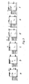
- a stacking device for rod-shaped or board-shaped piece goods regularly comprises at least two stands 1 which are displaceably arranged on a frame frame 2 at a distance from one another.
- the stacking device has the task of neatly stacking the boards 4 (or other rod-shaped or board-shaped piece goods) arriving on the rear side 3 from feed devices (not shown) on the front side 5 in a stack 6 on a pallet 7.
- the stator 1 has two revolving chains 8, 9 in its interior, which are offset in the longitudinal direction of the stator 1 and are arranged parallel to one another in the transverse direction, as can be seen from FIGS. 1 and 2.
- the chains 8, 9 are driven in the direction of the arrow 10 by drives (not shown) and run around chain wheels 11 arranged in corner points. Between the chains 8, 9 arranged parallel to each other, drivers 12 with fixed stops 13 are arranged in the manner described below, which run together with the chains 8, 9 in the direction of arrow 10.
- Each driver 12 promotes a board 4 on the back 3 of the stand 1 upwards onto the top of the stand 1 designed as a storage surface 14.
- the storage surface 14 extends at least by the width 15 of a stack row 16 to be formed over that of the fixed stop 13 of each one - Nehmers 12 on the top of the stand through the route.
- the storage surface 14 is formed by the top of the stand 1 and can be designed by a corresponding slide rail.
- the distance traveled by the fixed stop 13 on the top of the stand 1 is exactly limited by the start of the downward movement of the drivers along the chains 8, 9 according to the arrow 17. If adjustable fixed stops 13 are provided on the drivers 12 in a manner not shown in detail, the time at which the fixed stops 13 plunge into the surface of the storage surface 14 can be changed become.
- the boards 4 are conveyed by means of the drivers 12 onto the storage surface 14, deposited there and only pushed from the fixed stop 13 of the subsequent driver 12 into the desired row of stacks 16.
- the stand 1 is given a width which corresponds approximately to 1.5 times the width of the chain drive 8, 9. If necessary, the back 3 of the stand 1 can be chamfered in accordance with the dashed line, so that the drivers 12 are guided along the chamfered rear 3 /. Accordingly, the front side 5 can be moved inwards below the storage surface 14.
- the stacking carriages 18 guided on slide guides of the stand 1 are driven by means of drives (not shown in detail) with the support arms 19 protruding beyond the upper edge of the stacking carriage 18 for lifting the stack row 16 below the storage surface 14 move vertically and lowered with the stack row 14 after the extension of the support arms 19 onto the stack 6, in order to deposit the stack row 16 here by pulling in the support arms 19. Then proceed the support arms 13 again in the vertical direction to remove the new stack row formed in the meantime.
- Retaining devices 20 for stack row 14 to be put down on the support arms 19 can be arranged on the stacking trolley 13.
- the retention device 20 can be designed as a pawl, simple ratchet or the like.
- the front 5 of the stand 1 can also serve as a retainer.
- FIG. 3 shows a stacking cycle.
- a new row of stacks is being formed while the stacker 13 is hiding the. Has placed the stack row.
- Fig. 3b the new stack row 14 is finished, the stacking carriage 13 has moved vertically.
- FIG. 3c the new stack row is being lifted, in FIG. 3d the stack row 14 is extended onto the support arm 19 and is lowered and set down in FIG. 3 e, while in FIG. 3 f the next stack row is formed again.
- 4ff shows a preferred embodiment of a connection between the drivers 12 and the associated chains 8, 9.
- the driver 12 is each connected to a link 21, 22 of both parallel chains 8 and 9 via a rotating piece 23, 24, which is rotatably mounted in the driver 12 and laterally immovable by circlips and with both bolts 25, 26 and 27 , 28 of the respective chain link 21 or 22 is rigidly connected.
- This form of training ensures a secure, articulated connection between chain 8, 9 and driver 12. If a chain link 21, 22 of a chain 8 or 9 is deflected around a chain wheel 11, the rotating piece 23, 24 can be located in the driver 12 turn without moving sideways. The drivers 12 consequently remain in the desired horizontal position.
- FIG. 4 shows an alternative embodiment of a driver 12 with drivers 13 arranged at the rear end.
- Photocells 29 or components having a similar function can be arranged on the stacking carriage 18 and, together with an electronic control device (not shown in more detail), control the lowering of the stacking carriage 18 as a function of the height of the upper edge of the previously stacked row 16.
- Electronic piece number counters 30 can be attached to count the number of pieces per stack row 16.
- 14 layer counters 31 can be attached in the area of the stack rows being lowered.
- the stack row 16 formed on the storage surface 14 can also be pushed onto the already extended support arm 19 in an alternative mode of operation of the stacking device.
- a stacking carriage 18 with a support arm 19 can be arranged on both sides of each stand 1, which alternately convey a stack row 16 downwards.
- the front wall 5 of the stand 1 can serve as a retainer.
- the storage surface 14 can be formed by a rigid arm on which the stack row 16 is pre-formed and from which the stack row 16 is lifted by means of the vertically movable stacking carriage 18 with support arms 19.
Landscapes
- Engineering & Computer Science (AREA)
- Mechanical Engineering (AREA)
- Stacking Of Articles And Auxiliary Devices (AREA)
Applications Claiming Priority (2)
| Application Number | Priority Date | Filing Date | Title |
|---|---|---|---|
| DE2735469 | 1977-08-03 | ||
| DE2735469A DE2735469B2 (de) | 1977-08-03 | 1977-08-03 | Stapelvorrichtung für stab- oder brettförmiges Stückgut |
Publications (2)
| Publication Number | Publication Date |
|---|---|
| EP0000708A1 true EP0000708A1 (fr) | 1979-02-21 |
| EP0000708B1 EP0000708B1 (fr) | 1980-07-23 |
Family
ID=6015770
Family Applications (1)
| Application Number | Title | Priority Date | Filing Date |
|---|---|---|---|
| EP78100409A Expired EP0000708B1 (fr) | 1977-08-03 | 1978-07-17 | Dispositif d'empilage d'objets en forme de baguettes ou de planches |
Country Status (6)
| Country | Link |
|---|---|
| US (1) | US4193725A (fr) |
| EP (1) | EP0000708B1 (fr) |
| JP (1) | JPS5453470A (fr) |
| AT (1) | AT359920B (fr) |
| DE (2) | DE2735469B2 (fr) |
| IT (1) | IT1192261B (fr) |
Cited By (2)
| Publication number | Priority date | Publication date | Assignee | Title |
|---|---|---|---|---|
| FR2473021A1 (fr) * | 1979-09-14 | 1981-07-10 | Laessig Foerdertech Hamburg | Chargeur de palettes concu pour des marchandises en colis, et tout specialement des paquets, sacs ou equivalent, groupees en differentes couches correspondant aux dimensions des palettes |
| FR2628722A1 (fr) * | 1988-03-16 | 1989-09-22 | Man Francois | Machine pour constituer et empiler des lits de pieces allongees |
Families Citing this family (12)
| Publication number | Priority date | Publication date | Assignee | Title |
|---|---|---|---|---|
| DE2920935C2 (de) * | 1979-05-21 | 1983-10-27 | Heinz 1000 Berlin Schiepe | Stapelvorrichtung für stab- oder brettförmiges Stückgut |
| EP0020287B1 (fr) * | 1979-05-21 | 1983-03-09 | Heinz Schiepe | Dispositif pour le désempilage de couches empilées |
| DE3466866D1 (en) * | 1983-07-20 | 1987-11-26 | Paul Truninger | Loading device for elongate objects |
| DE3616921A1 (de) * | 1986-05-20 | 1987-11-26 | Haist Kg Karl | Einrichtung zum stapeln von brettern |
| US4836731A (en) * | 1988-03-07 | 1989-06-06 | Builders Equipment Company | Method and apparatus for cubing stones of diverse geometries |
| US5073081A (en) * | 1989-08-14 | 1991-12-17 | Johnson Nolton C | Automatic self-contained stacking machine |
| US4986411A (en) * | 1989-09-19 | 1991-01-22 | H. G. Weber & Co., Inc. | Continuous motion vertical conveyor |
| AT395311B (de) * | 1991-01-17 | 1992-11-25 | Schelling & Co | Gabelstapelgeraet fuer aufteil- und sortieranlagen bei aufteilsaegemaschinen |
| ES2068081B1 (es) * | 1992-05-05 | 1997-11-01 | Esteban Roca Javier | Paletizadora de molduras perfeccionada y su procedimiento de funcionamiento. |
| US5636967A (en) * | 1995-09-22 | 1997-06-10 | Green; David C. | Board handling apparatus |
| EP0918716B1 (fr) * | 1996-05-03 | 2003-11-05 | Busse Bros., Inc. | Unite de manipulation de feuilles de separation pour palettiseur |
| DE102010007160A1 (de) * | 2010-02-05 | 2011-08-11 | Sicko, Carlo, 75059 | Verfahren und Vorrichtung zum Paketieren von Holzleisten |
Citations (9)
| Publication number | Priority date | Publication date | Assignee | Title |
|---|---|---|---|---|
| DE467927C (de) * | 1928-11-03 | C A Neubecker G M B H | Plattenfoerderer mit Fuehrung der Platten in stets waagerechter Ebene | |
| DE1198286B (de) * | 1961-06-06 | 1965-08-05 | Halvor Graasvoll | Maschine zum lageweisen Stapeln von Stueckgut auf einer Ladeplatte |
| FR1414053A (fr) * | 1964-09-02 | 1965-10-15 | Perfectionnements aux dispositifs transporteurs à chaînes, notamment pour bouteilles ou autres objets analogues devant être déplacés en suivant une orientation donnée | |
| DE1808973A1 (de) * | 1968-11-14 | 1970-06-04 | Moore Iem Inc | Bauholzstapler |
| DE2020441A1 (de) * | 1970-04-27 | 1971-12-02 | Keller & Co Masch C | Einrichtung zum Transport von auf Formlingstraegern gelagerten oder formlingstraegerfreien keramischen Formlingen |
| NL7109892A (fr) * | 1971-07-16 | 1973-01-18 | ||
| US3737053A (en) * | 1972-01-03 | 1973-06-05 | Moore Iem Inc | Lumber stacking apparatus |
| NL7202343A (fr) * | 1972-02-23 | 1973-08-27 | ||
| CH554796A (de) * | 1973-02-15 | 1974-10-15 | Balz Rudolf | Einrichtung zum bilden von bretterlagen, die dazu bestimmt sind, zu einem stapel mit parallelen laengsseiten aufeinandergeschichtet zu werden. |
Family Cites Families (1)
| Publication number | Priority date | Publication date | Assignee | Title |
|---|---|---|---|---|
| DE1235808B (de) * | 1963-04-27 | 1967-03-02 | Schiepe Holzbearbeitungsmasch | Stapelvorrichtung fuer stab- und brettfoermiges Stueckgut, insbesondere fuer Profilleisten |
-
1977
- 1977-08-03 DE DE2735469A patent/DE2735469B2/de not_active Ceased
-
1978
- 1978-07-17 DE DE7878100409T patent/DE2860068D1/de not_active Expired
- 1978-07-17 EP EP78100409A patent/EP0000708B1/fr not_active Expired
- 1978-07-19 AT AT521678A patent/AT359920B/de not_active IP Right Cessation
- 1978-07-21 IT IT25993/78A patent/IT1192261B/it active
- 1978-07-24 US US05/927,508 patent/US4193725A/en not_active Expired - Lifetime
- 1978-08-03 JP JP9515878A patent/JPS5453470A/ja active Granted
Patent Citations (9)
| Publication number | Priority date | Publication date | Assignee | Title |
|---|---|---|---|---|
| DE467927C (de) * | 1928-11-03 | C A Neubecker G M B H | Plattenfoerderer mit Fuehrung der Platten in stets waagerechter Ebene | |
| DE1198286B (de) * | 1961-06-06 | 1965-08-05 | Halvor Graasvoll | Maschine zum lageweisen Stapeln von Stueckgut auf einer Ladeplatte |
| FR1414053A (fr) * | 1964-09-02 | 1965-10-15 | Perfectionnements aux dispositifs transporteurs à chaînes, notamment pour bouteilles ou autres objets analogues devant être déplacés en suivant une orientation donnée | |
| DE1808973A1 (de) * | 1968-11-14 | 1970-06-04 | Moore Iem Inc | Bauholzstapler |
| DE2020441A1 (de) * | 1970-04-27 | 1971-12-02 | Keller & Co Masch C | Einrichtung zum Transport von auf Formlingstraegern gelagerten oder formlingstraegerfreien keramischen Formlingen |
| NL7109892A (fr) * | 1971-07-16 | 1973-01-18 | ||
| US3737053A (en) * | 1972-01-03 | 1973-06-05 | Moore Iem Inc | Lumber stacking apparatus |
| NL7202343A (fr) * | 1972-02-23 | 1973-08-27 | ||
| CH554796A (de) * | 1973-02-15 | 1974-10-15 | Balz Rudolf | Einrichtung zum bilden von bretterlagen, die dazu bestimmt sind, zu einem stapel mit parallelen laengsseiten aufeinandergeschichtet zu werden. |
Cited By (2)
| Publication number | Priority date | Publication date | Assignee | Title |
|---|---|---|---|---|
| FR2473021A1 (fr) * | 1979-09-14 | 1981-07-10 | Laessig Foerdertech Hamburg | Chargeur de palettes concu pour des marchandises en colis, et tout specialement des paquets, sacs ou equivalent, groupees en differentes couches correspondant aux dimensions des palettes |
| FR2628722A1 (fr) * | 1988-03-16 | 1989-09-22 | Man Francois | Machine pour constituer et empiler des lits de pieces allongees |
Also Published As
| Publication number | Publication date |
|---|---|
| DE2860068D1 (en) | 1980-11-13 |
| US4193725A (en) | 1980-03-18 |
| IT1192261B (it) | 1988-03-31 |
| IT7825993A0 (it) | 1978-07-21 |
| ATA521678A (de) | 1980-04-15 |
| AT359920B (de) | 1980-12-10 |
| DE2735469A1 (de) | 1979-03-15 |
| EP0000708B1 (fr) | 1980-07-23 |
| JPS5453470A (en) | 1979-04-26 |
| JPS6143253B2 (fr) | 1986-09-26 |
| DE2735469B2 (de) | 1979-07-12 |
Similar Documents
| Publication | Publication Date | Title |
|---|---|---|
| EP0407703B1 (fr) | Procédé et dispositif pour stocker et déstocker des caissons contenant des matériaux en forme de bâton ou de plaque dans un magasin à rayonnage | |
| DE4016810C1 (fr) | ||
| DE3940865C1 (fr) | ||
| DE3217914C2 (fr) | ||
| DE2509223C3 (de) | Lastgabevorrichtung eines Regalförderzeuges | |
| DE2714333A1 (de) | Vorrichtung zum selbsttaetigen verladen von saecken mit einem stapelbildner | |
| EP0000708B1 (fr) | Dispositif d'empilage d'objets en forme de baguettes ou de planches | |
| DE3824230A1 (de) | Vorrichtung zum transport von werkstuecken | |
| DE3504491A1 (de) | Vorrichtung zum anlegen von bogen | |
| DE9103197U1 (de) | Regalbediengerät für Hochregallager | |
| DE69303173T2 (de) | Regalbedienungsgrät mit gabeln dopplter reichweite | |
| DE4031883A1 (de) | Aufnahme- und abgabesystem fuer paletten und behaelter | |
| DE2758226C2 (de) | Warenmagazin für Behälter, Paletten o.dgl. | |
| DE1285402B (de) | Vorrichtung zum Stapeln von Barren | |
| DE4432856C2 (de) | Aufnahmevorrichtung für Paletten | |
| DE3527746C2 (fr) | ||
| DE3113976C2 (de) | Maschine zum schichtenweisen Be- oder Entpalettieren von Stückgut | |
| DE4426615C1 (de) | Vorrichtung zum Stapeln oder Entstapeln von stapelbarem Gut | |
| WO1991000232A1 (fr) | Chariot d'entreposage et de transfert de porteurs de marchandises | |
| DE2716490C3 (de) | Vorrichtung zum Beladen von Paletten mit Stückgütern, insbesondere Paketen, Säcken o.dgl. | |
| DE4314600B4 (de) | Vorrichtung zur lageweisen Stapelung von gruppierten Gegenständen | |
| DE3343528A1 (de) | Einrichtung zur lagerung von materialien, insbesondere langgut, wie kassetten o.dgl. | |
| DE7724470U1 (de) | Stapelvorrichtung fuer stab- oder brettfoermiges stueckgut | |
| DE2731579A1 (de) | Stapelvorrichtung fuer profilstaebe aus stahl | |
| DE2322240C3 (de) | Anlage zum Stapeln von Metallbarren (Gußblöcken) zu einem Paket |
Legal Events
| Date | Code | Title | Description |
|---|---|---|---|
| PUAI | Public reference made under article 153(3) epc to a published international application that has entered the european phase |
Free format text: ORIGINAL CODE: 0009012 |
|
| AK | Designated contracting states |
Designated state(s): BE CH DE FR GB LU NL SE |
|
| 17P | Request for examination filed | ||
| GRAA | (expected) grant |
Free format text: ORIGINAL CODE: 0009210 |
|
| AK | Designated contracting states |
Designated state(s): BE CH FR GB LU NL SE |
|
| REF | Corresponds to: |
Ref document number: 2860068 Country of ref document: DE Date of ref document: 19801113 |
|
| PG25 | Lapsed in a contracting state [announced via postgrant information from national office to epo] |
Ref country code: LU Free format text: LAPSE BECAUSE OF NON-PAYMENT OF DUE FEES Effective date: 19810731 |
|
| PGFP | Annual fee paid to national office [announced via postgrant information from national office to epo] |
Ref country code: LU Payment date: 19830620 Year of fee payment: 6 |
|
| REG | Reference to a national code |
Ref country code: GB Ref legal event code: 732 |
|
| REG | Reference to a national code |
Ref country code: CH Ref legal event code: PUE Owner name: SCHIEPE STAPELAUTOMATEN GMBH |
|
| REG | Reference to a national code |
Ref country code: FR Ref legal event code: TP |
|
| NLS | Nl: assignments of ep-patents |
Owner name: SCHIEPE STAPELAUTOMATEN GMBH TE BERLIJN, BONDSREPU |
|
| PGFP | Annual fee paid to national office [announced via postgrant information from national office to epo] |
Ref country code: NL Payment date: 19900731 Year of fee payment: 13 |
|
| PGFP | Annual fee paid to national office [announced via postgrant information from national office to epo] |
Ref country code: FR Payment date: 19901116 Year of fee payment: 13 |
|
| PGFP | Annual fee paid to national office [announced via postgrant information from national office to epo] |
Ref country code: CH Payment date: 19901119 Year of fee payment: 13 |
|
| PGFP | Annual fee paid to national office [announced via postgrant information from national office to epo] |
Ref country code: SE Payment date: 19901123 Year of fee payment: 13 |
|
| PGFP | Annual fee paid to national office [announced via postgrant information from national office to epo] |
Ref country code: BE Payment date: 19901204 Year of fee payment: 13 |
|
| PGFP | Annual fee paid to national office [announced via postgrant information from national office to epo] |
Ref country code: GB Payment date: 19901210 Year of fee payment: 13 |
|
| PG25 | Lapsed in a contracting state [announced via postgrant information from national office to epo] |
Ref country code: GB Effective date: 19910717 |
|
| PG25 | Lapsed in a contracting state [announced via postgrant information from national office to epo] |
Ref country code: SE Effective date: 19910718 |
|
| PG25 | Lapsed in a contracting state [announced via postgrant information from national office to epo] |
Ref country code: BE Effective date: 19910731 Ref country code: CH Effective date: 19910731 |
|
| BERE | Be: lapsed |
Owner name: SCHIEPE STAPELAUTOMATEN G.M.B.H. Effective date: 19910731 |
|
| PG25 | Lapsed in a contracting state [announced via postgrant information from national office to epo] |
Ref country code: NL Effective date: 19920201 |
|
| NLV4 | Nl: lapsed or anulled due to non-payment of the annual fee | ||
| GBPC | Gb: european patent ceased through non-payment of renewal fee | ||
| PG25 | Lapsed in a contracting state [announced via postgrant information from national office to epo] |
Ref country code: FR Effective date: 19920331 |
|
| REG | Reference to a national code |
Ref country code: CH Ref legal event code: PL |
|
| REG | Reference to a national code |
Ref country code: FR Ref legal event code: ST |
|
| EUG | Se: european patent has lapsed |
Ref document number: 78100409.8 Effective date: 19920210 |
|
| PLBE | No opposition filed within time limit |
Free format text: ORIGINAL CODE: 0009261 |
|
| STAA | Information on the status of an ep patent application or granted ep patent |
Free format text: STATUS: NO OPPOSITION FILED WITHIN TIME LIMIT |