EP0000862A1 - Caniveau d'écoulement de plancher pour chambres humides - Google Patents
Caniveau d'écoulement de plancher pour chambres humides Download PDFInfo
- Publication number
- EP0000862A1 EP0000862A1 EP78100119A EP78100119A EP0000862A1 EP 0000862 A1 EP0000862 A1 EP 0000862A1 EP 78100119 A EP78100119 A EP 78100119A EP 78100119 A EP78100119 A EP 78100119A EP 0000862 A1 EP0000862 A1 EP 0000862A1
- Authority
- EP
- European Patent Office
- Prior art keywords
- drainage channel
- floor
- channel according
- sections
- longitudinal
- Prior art date
- Legal status (The legal status is an assumption and is not a legal conclusion. Google has not performed a legal analysis and makes no representation as to the accuracy of the status listed.)
- Withdrawn
Links
- 238000011010 flushing procedure Methods 0.000 claims description 4
- 230000001154 acute effect Effects 0.000 claims description 2
- 239000002689 soil Substances 0.000 claims 6
- 238000004140 cleaning Methods 0.000 abstract 1
- 238000005192 partition Methods 0.000 abstract 1
- 238000004659 sterilization and disinfection Methods 0.000 abstract 1
- XLYOFNOQVPJJNP-UHFFFAOYSA-N water Substances O XLYOFNOQVPJJNP-UHFFFAOYSA-N 0.000 description 5
- 238000009434 installation Methods 0.000 description 2
- 239000007921 spray Substances 0.000 description 2
- 239000000356 contaminant Substances 0.000 description 1
- 238000009408 flooring Methods 0.000 description 1
- 238000003780 insertion Methods 0.000 description 1
- 230000037431 insertion Effects 0.000 description 1
- 238000004519 manufacturing process Methods 0.000 description 1
- 239000002184 metal Substances 0.000 description 1
- 238000012986 modification Methods 0.000 description 1
- 230000004048 modification Effects 0.000 description 1
Images


Classifications
-
- E—FIXED CONSTRUCTIONS
- E03—WATER SUPPLY; SEWERAGE
- E03F—SEWERS; CESSPOOLS
- E03F5/00—Sewerage structures
- E03F5/04—Gullies inlets, road sinks, floor drains with or without odour seals or sediment traps
- E03F5/06—Gully gratings
-
- E—FIXED CONSTRUCTIONS
- E01—CONSTRUCTION OF ROADS, RAILWAYS, OR BRIDGES
- E01C—CONSTRUCTION OF, OR SURFACES FOR, ROADS, SPORTS GROUNDS, OR THE LIKE; MACHINES OR AUXILIARY TOOLS FOR CONSTRUCTION OR REPAIR
- E01C11/00—Details of pavings
- E01C11/22—Gutters; Kerbs ; Surface drainage of streets, roads or like traffic areas
- E01C11/224—Surface drainage of streets
- E01C11/227—Gutters; Channels ; Roof drainage discharge ducts set in sidewalks
-
- Y—GENERAL TAGGING OF NEW TECHNOLOGICAL DEVELOPMENTS; GENERAL TAGGING OF CROSS-SECTIONAL TECHNOLOGIES SPANNING OVER SEVERAL SECTIONS OF THE IPC; TECHNICAL SUBJECTS COVERED BY FORMER USPC CROSS-REFERENCE ART COLLECTIONS [XRACs] AND DIGESTS
- Y02—TECHNOLOGIES OR APPLICATIONS FOR MITIGATION OR ADAPTATION AGAINST CLIMATE CHANGE
- Y02A—TECHNOLOGIES FOR ADAPTATION TO CLIMATE CHANGE
- Y02A30/00—Adapting or protecting infrastructure or their operation
- Y02A30/60—Planning or developing urban green infrastructure
Definitions
- the invention relates to a floor drainage channel which can be connected to at least one drain line for wet rooms, in particular for commercial kitchens, slaughterhouses and the like.
- the channel body consists of a plurality of sections which are open on the end face and releasably attached to one another with their end faces and of a plurality of end walls which are releasably attached to the end face, the sections which may have a different floor depth at the ends being provided with outwardly projecting fastening flanges, which have the same connection dimensions with each other and with the end walls.
- the channel is now assembled from several parts of a kit.
- the kit contains a section with a drain opening or a connection collar for a floor drain, several different long and / or different depth channel sections and a type of end walls.
- a suitable gutter can be put together for every application, whereby it is only necessary to ensure that each section has an uninterrupted gradient towards the nearest drain opening.
- end walls can also be inserted where the slope has the highest elevation. There they are used for further stiffening.
- Another The strength can be increased in that the bottom of each section has a transverse slope directed from both sides towards the longitudinal center. The floor therefore has a kink in the longitudinal direction, which increases the security against buckling.
- this kink is a longitudinal groove and provide the sloping bottom sections with transverse grooves, then in addition to the rigidity, the drainage behavior is also improved, namely by the fact that the water flows in the grooves at a higher speed and contaminants do not give an opportunity for unwanted settling. This also applies if the water comes from an additionally provided rinsing device.
- a very advantageous possibility of connecting the channel sections is described in more detail below in addition to further details of the innovation using the drawings.
- the bottom drainage channel shown in Fig. 1 consists of a main section 1 with a collar 2 for connection to a floor drain (not shown), an additional section 3 and two identically designed end walls 4.
- the sections and the end walls are connected by screws 5 and by gaskets sealed to the outside.
- Pads 6 for the inlet grates 7 are provided on the longitudinal walls.
- the floor is given a downward bend in the longitudinal center, which results in a transverse gradient directed from both sides towards the longitudinal center.
- each main section 1 is assigned two additional sections 3, 13, which have such a different depth that in connection with the slope of the main section 1 there is a continuous slope.
- the channel can continue to the right in any repetition. Since practically no water runs from the additional section 13 into the main section 1 adjacent to the left, a transverse wall can also be installed at this point, which is very useful for the rigidity.
- FIG. 3 A somewhat shorter gutter consisting of a total of four sections is shown in FIG. 3.
- a symmetrical arrangement is made in such a way that between two outer main sections 1, two additional sections 3 are arranged in mirror image to one another and are closed at the end by connecting walls 4.
- two further additional sections 13 By inserting two further additional sections 13, as e.g. 2 can be seen, this channel design can be extended as desired.
- each flange 8 and 18 belonging to a channel section 3, 13 contains an equal number of holes 9 and set screws lo. These are arranged so that each hole 9 on the flange section symmetrical to the center line 11 is a threaded pin lo opposite.
- the hole 9 and the grub screw lo ' form the first pair
- the grub screw lo and the hole 9' form the second pair
- the hole 9 '' and the grub screw lo '' form the third pair.
- an end wall 4 does not pose any difficulties if, as shown, it has through holes 19 at the six connection points. If the end wall is attached to the end of the channel, then three setscrews lo projecting from the adjacent flange are available for fastening it; screws are attached to the three remaining fastening points.
- the flanges 8 and 18 are kept somewhat shorter at the top than the longitudinal wall of the channel section.
- the end wall 4 also contains cutouts at these points. It is thereby achieved that of the entire drainage channel only the edges of the channel body comprising the inlet grates are flush and visible with the floor. The tiles used as flooring can be laid all the way up to these edges.
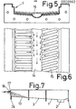
- FIGS. 5 and 6 show a channel section 21, the bottom of which has a transverse slope directed towards the longitudinal groove 14 running in the longitudinal center.
- the bottom is provided with transverse grooves 15 running in the direction of this slope, which open into the longitudinal groove at right angles or at an acute angle.
- the end wall 24 attached to the outermost section 13 is provided with a bulge 16 which receives a spray tube 17.
- the spray jets emanating from it cover essentially the entire floor of this section.
- gutter sections can be provided with sheet metal tabs on the outside that protrude outwards and for better anchorage in the ceiling serve. These tabs can be folded flat during transport and only bent outwards shortly before installation. Height-adjustable support feet can be provided on the bottom of the channel sections as an adjustment aid when embedding.
- the collecting groove running in the direction of the longitudinal slope of the channel bottom can be arranged asymmetrically or entirely on one longitudinal side. In the case of channels with a large width, several longitudinal grooves are also conceivable.
Landscapes
- Engineering & Computer Science (AREA)
- Health & Medical Sciences (AREA)
- Life Sciences & Earth Sciences (AREA)
- Hydrology & Water Resources (AREA)
- Public Health (AREA)
- Water Supply & Treatment (AREA)
- Architecture (AREA)
- Civil Engineering (AREA)
- Structural Engineering (AREA)
- Floor Finish (AREA)
Applications Claiming Priority (6)
| Application Number | Priority Date | Filing Date | Title |
|---|---|---|---|
| DE7725889U DE7725889U1 (de) | 1977-08-20 | 1977-08-20 | Bodenentwaesserungsrinne fuer nassraeume |
| DE7725889U | 1977-08-20 | ||
| DE7804071U | 1978-02-11 | ||
| DE19787804071 DE7804071U1 (de) | 1978-02-11 | 1978-02-11 | Bodenentwaesserungsrinne mit spuelvorrichtung |
| DE19787813053 DE7813053U1 (de) | 1978-04-28 | 1978-04-28 | Bodenentwaesserungsrinne fuer nassraeume |
| DE7813053U | 1978-04-28 |
Publications (1)
| Publication Number | Publication Date |
|---|---|
| EP0000862A1 true EP0000862A1 (fr) | 1979-03-07 |
Family
ID=27207421
Family Applications (1)
| Application Number | Title | Priority Date | Filing Date |
|---|---|---|---|
| EP78100119A Withdrawn EP0000862A1 (fr) | 1977-08-20 | 1978-06-08 | Caniveau d'écoulement de plancher pour chambres humides |
Country Status (1)
| Country | Link |
|---|---|
| EP (1) | EP0000862A1 (fr) |
Cited By (5)
| Publication number | Priority date | Publication date | Assignee | Title |
|---|---|---|---|---|
| WO1999039057A1 (fr) * | 1998-01-28 | 1999-08-05 | Selwyn Reed | Ensemble d'evacuation des dechets permettant l'insertion d'un appareil ou d'un deverseur de dechets de surface |
| WO2001041843A1 (fr) | 1999-12-13 | 2001-06-14 | Futura Medical Technologies, Inc. | Seringue à ensemble aiguille rétractable |
| WO2002065911A1 (fr) | 2001-02-20 | 2002-08-29 | Medisys Asia Pacific Pte Ltd | Dispositif de lancette muni d'un element tranchant retractable |
| WO2006120275A1 (fr) * | 2005-05-13 | 2006-11-16 | Universidad Politécnica de Madrid | Prefabrique modulaire destine au drainage superficiel dans des chemins de terre |
| WO2017191127A1 (fr) * | 2016-05-04 | 2017-11-09 | ACO Severin Ahlmann GmbH & Co Kommanditgesellschaft | Paroi frontale d'un caniveau de drainage superficiel |
Citations (7)
| Publication number | Priority date | Publication date | Assignee | Title |
|---|---|---|---|---|
| CH107354A (fr) * | 1924-02-11 | 1925-03-16 | Freres Zbinden | Dalle pour locaux destinés à recevoir des animaux. |
| US2701027A (en) * | 1952-10-13 | 1955-02-01 | Thomas N Scoville | Floor drain master |
| FR1181762A (fr) * | 1957-08-29 | 1959-06-18 | Perfectionnements aux systèmes de pavage assurant l'écoulement des liquides et plus particulièrement des liquides corrosifs | |
| GB916105A (en) * | 1960-12-23 | 1963-01-23 | Jerrold Stuart Newman | Drainage structure |
| US3225545A (en) * | 1962-07-10 | 1965-12-28 | Josam Mfg Co | Drain construction |
| DE2254364A1 (de) * | 1972-11-07 | 1974-07-04 | Hauger & Jaegel Gmbh | Plattenartiges oberflaechenentwaesserungsrinnensystem |
| FR2210204A5 (fr) * | 1972-12-07 | 1974-07-05 | Farge Claude |
-
1978
- 1978-06-08 EP EP78100119A patent/EP0000862A1/fr not_active Withdrawn
Patent Citations (7)
| Publication number | Priority date | Publication date | Assignee | Title |
|---|---|---|---|---|
| CH107354A (fr) * | 1924-02-11 | 1925-03-16 | Freres Zbinden | Dalle pour locaux destinés à recevoir des animaux. |
| US2701027A (en) * | 1952-10-13 | 1955-02-01 | Thomas N Scoville | Floor drain master |
| FR1181762A (fr) * | 1957-08-29 | 1959-06-18 | Perfectionnements aux systèmes de pavage assurant l'écoulement des liquides et plus particulièrement des liquides corrosifs | |
| GB916105A (en) * | 1960-12-23 | 1963-01-23 | Jerrold Stuart Newman | Drainage structure |
| US3225545A (en) * | 1962-07-10 | 1965-12-28 | Josam Mfg Co | Drain construction |
| DE2254364A1 (de) * | 1972-11-07 | 1974-07-04 | Hauger & Jaegel Gmbh | Plattenartiges oberflaechenentwaesserungsrinnensystem |
| FR2210204A5 (fr) * | 1972-12-07 | 1974-07-05 | Farge Claude |
Cited By (11)
| Publication number | Priority date | Publication date | Assignee | Title |
|---|---|---|---|---|
| WO1999039057A1 (fr) * | 1998-01-28 | 1999-08-05 | Selwyn Reed | Ensemble d'evacuation des dechets permettant l'insertion d'un appareil ou d'un deverseur de dechets de surface |
| US6755966B1 (en) * | 1998-01-28 | 2004-06-29 | Selwyn Reed | Waste assembly allowing adjustable fitment of a floor waste or appliance |
| WO2001041843A1 (fr) | 1999-12-13 | 2001-06-14 | Futura Medical Technologies, Inc. | Seringue à ensemble aiguille rétractable |
| WO2001041830A2 (fr) | 1999-12-13 | 2001-06-14 | Futura Medical Technologies, Inc. | Seringue a ensemble d'aiguille escamotable |
| WO2002065911A1 (fr) | 2001-02-20 | 2002-08-29 | Medisys Asia Pacific Pte Ltd | Dispositif de lancette muni d'un element tranchant retractable |
| WO2006120275A1 (fr) * | 2005-05-13 | 2006-11-16 | Universidad Politécnica de Madrid | Prefabrique modulaire destine au drainage superficiel dans des chemins de terre |
| ES2262437A1 (es) * | 2005-05-13 | 2006-11-16 | Universidad Politecnica De Madrid | Prefabricado modular para el drenaje superficial en caminos de tierra. |
| ES2262437B2 (es) * | 2005-05-13 | 2007-06-16 | Universidad Politecnica De Madrid | Prefabricado modular para el drenaje superficial en caminos de tierra. |
| WO2017191127A1 (fr) * | 2016-05-04 | 2017-11-09 | ACO Severin Ahlmann GmbH & Co Kommanditgesellschaft | Paroi frontale d'un caniveau de drainage superficiel |
| CN109072599A (zh) * | 2016-05-04 | 2018-12-21 | 亚科赛福林阿尔曼有限公司 | 用于表面排水的排水沟的端壁 |
| CN109072599B (zh) * | 2016-05-04 | 2021-05-04 | 亚科赛福林阿尔曼有限公司 | 用于表面排水的排水沟的端壁 |
Similar Documents
| Publication | Publication Date | Title |
|---|---|---|
| CH640031A5 (de) | Sanitaerraumkabine. | |
| EP3024990B1 (fr) | Bouche d'egout | |
| DE3309460C2 (fr) | ||
| DE19632026C1 (de) | Leitschutzsystem, insbesondere zur Sicherung von Verkehrswegen | |
| DE102007048329B3 (de) | Entwässerungsrinne | |
| EP0056238B1 (fr) | Dispositif de drainage pour terrains de sport | |
| CH714146A2 (de) | Wasserführungseinheit für eine Fischaufstiegsanlage und Fischaufstiegsanlage mit einer Mehrzahl von miteinander verbundenden Wasserführungseinheiten. | |
| DE7725889U1 (de) | Bodenentwaesserungsrinne fuer nassraeume | |
| AT379420B (de) | Tragrahmen zur halterung von geraeten der installationstechnik an gebaeudewaenden | |
| DE9110913U1 (de) | Sanitärelement | |
| DE102015111423A1 (de) | Befestigungsvorrichtung und Montagerahmen für Sanitärelemente | |
| DE4031922C2 (fr) | ||
| DE102014104722A1 (de) | Schalung für zu erstellende Mauern | |
| DE2009099C3 (de) | Abzugs- und Abflußkanalanlage für Gebäude | |
| DE102019106003B3 (de) | Waschtisch | |
| DE3820880C2 (de) | Begrenzung von Laufbahnen in Sportanlagen oder dergleichen Anlagen | |
| DE1679539A1 (de) | Verteilkanal fuer uebersaettigte Luft von einer Lueftungs- und Klimaanlage | |
| DE3100347C2 (de) | Drainagevorrichtung für Sportplätze | |
| DE10043054C1 (de) | Stütze zur Erstellung von Gebäuden | |
| DE9415180U1 (de) | Sanitär-Vorwand | |
| EP0908567A1 (fr) | Tirant d'ancrage pour cadre | |
| DE19833649C2 (de) | Tragelemente für Duschabtrennungen | |
| DE102012102920A1 (de) | Beckenkonstruktion für eine Fischwanderhilfe in Kombination mit einem Wasserwirbelkraftwerk | |
| AT414207B (de) | Aufhängevorrichtung für einen duschvorhang | |
| EP1223253A1 (fr) | Ensemble sanitaire |
Legal Events
| Date | Code | Title | Description |
|---|---|---|---|
| PUAI | Public reference made under article 153(3) epc to a published international application that has entered the european phase |
Free format text: ORIGINAL CODE: 0009012 |
|
| AK | Designated contracting states |
Designated state(s): BE CH FR LU NL |
|
| 17P | Request for examination filed | ||
| STAA | Information on the status of an ep patent application or granted ep patent |
Free format text: STATUS: THE APPLICATION HAS BEEN WITHDRAWN |
|
| 18W | Application withdrawn | ||
| RIN1 | Information on inventor provided before grant (corrected) |
Inventor name: MEYER, THOMAS, ING. (GRAD) Inventor name: MEYER, HORST Inventor name: PLETTENBERG, WERNER,DIPL.-WIRTSCHAFTS-ING. Inventor name: HICKL, HERBERT Inventor name: KUNZ, DIETER,ING. (GRAD) |