EP0000964A1 - Vorrichtung zur Entwicklung eines elektrostatischen Ladungsbildes mittels Magnetbürsten. - Google Patents
Vorrichtung zur Entwicklung eines elektrostatischen Ladungsbildes mittels Magnetbürsten. Download PDFInfo
- Publication number
- EP0000964A1 EP0000964A1 EP78200120A EP78200120A EP0000964A1 EP 0000964 A1 EP0000964 A1 EP 0000964A1 EP 78200120 A EP78200120 A EP 78200120A EP 78200120 A EP78200120 A EP 78200120A EP 0000964 A1 EP0000964 A1 EP 0000964A1
- Authority
- EP
- European Patent Office
- Prior art keywords
- developing
- developing rollers
- reservoir
- rollers
- powder
- Prior art date
- Legal status (The legal status is an assumption and is not a legal conclusion. Google has not performed a legal analysis and makes no representation as to the accuracy of the status listed.)
- Granted
Links
Images
Classifications
-
- G—PHYSICS
- G03—PHOTOGRAPHY; CINEMATOGRAPHY; ANALOGOUS TECHNIQUES USING WAVES OTHER THAN OPTICAL WAVES; ELECTROGRAPHY; HOLOGRAPHY
- G03G—ELECTROGRAPHY; ELECTROPHOTOGRAPHY; MAGNETOGRAPHY
- G03G15/00—Apparatus for electrographic processes using a charge pattern
- G03G15/06—Apparatus for electrographic processes using a charge pattern for developing
- G03G15/08—Apparatus for electrographic processes using a charge pattern for developing using a solid developer, e.g. powder developer
- G03G15/09—Apparatus for electrographic processes using a charge pattern for developing using a solid developer, e.g. powder developer using magnetic brush
Definitions
- the invention relates to a device for the development of an electrostatic charge image on a moving substrate with the aid of magnetic brushes, which device comprises a trough-shaped reservoir of which two long opposite sloping walls lie in planes which are intersecting at the bottom of the reservoir, developing rollers installed in the upper part of the reservoir in parallel to the sloping walls, either of which rollers consists of a rotatable, non-magnetizable cylinder, in which stationary magnets have been installed, transport means installed between the bottom of the reservoir and the developing rollers, for the transport of the developing powder from the reservoir to the developing rollers, and means for mixing the developing powder.
- a magnetic brush with which charge images can be developed can be formed on the developing rollers of such a device.
- the known developing devices comprise one developing roller, which is partially immersed into a reservoir with developing powder, or which is mounted above the stock of developing powder and is provided with developing powder with the aid of a transport screw or a magnetic transport roller of similar nature as the developing roller.
- An embodiment with a magnetic transport roller is described in U.S. patent specification 3 654 902.
- a counterrunning roller which moves in opposite direction with regard to the charge image, has this disadvantage to a much lesser degree, but gives a bad development of the half tones. Moreover, when applying a binary developing powder, a counterrunning roller not only transfers toner but also a part of the magnetizable material to the charge image.
- a developing device which does not have the disadvantages mentioned above, is described in the British patent specification 1 373 010.
- the device according to the British patent specification comprises four developing rollers running in the same direction as the charge image.
- the developing powder is supplied to the first developing roller with the aid of a paddle wheel and is transported in a continuous stream over the four developing rollers which have been installed within each other's sphere of influence.
- By the repeated contact with the charge image a relatively long time of contact for the manufacture of copies with a high optical density is guaranteed, in spite of the high copying speed.
- After passing the fourth developing roller that part of the developing powder which has not been used falls into a mixing device via a scraper.
- This mixing device comprises a first row of tubular channels which have been installed in parallel with regard to each other, and a second row of channels which have been installed in parallel with regard to each other, which second row is fixed to the first row and crosses this first row. All these channels have been installed in a sloping way with regard to the free-fall direction of the developing powder, so that the developing powder is always split up into partial streams which arrive at different places in the reservoir.
- the developing device according to the British patent specification 1 373 010 also has various disadvantages.
- the four magnetic brushes on the four developing rollers form a great friction surface between the substrate of the charge image and the developing powder, so that the duration of use of the substrate and the developing powder is decreased.
- the device with four developing rollers is constructively less attractive, on the one hand because such-a device occupies much space, and a great surface on the substrate, and on the other hand because the construction of the mixing device is complicated.
- the device is only suitable for the development of charge images on a sloping substrate and the paddle wheel causes extra friction forces in the developing powder, so that especially with binary developing powders the particles of the magnetizable material which is not consumed but is reused again and again, are ageing and consequently have to be refreshed more frequently.
- the invention provides for a developing device which has the favourable properties of the developing device according to British patent specification 1 373 010 without the disadvantages of that device.
- the developing device according to the invention is a device, as described in the first paragraph, characterized in that a) the device comprises two developing rollers which have been installed out of each other's sphere of influence and the cylinders of these developing rollers have an opposite direction of rotation with which the cylinder surfaces, at the side which is directed towards the substrate, move away from each other, b) the transport means at least consist of a rotatable, non-magnetizable cylinder, installed in parallel to the developing rollers, and magnets, stationary installed in the cylinder, for the supply of developing powder between the developing rollers, and c) the mixing means consist of groups of parallelly erected partitions which have been fixed opposite to each other to the sloping walls of the reservoir, and the partitions of the one sloping wall lie in planes making a sharp angle with the shafts of the developing rollers and the partitions
- a charge image is first developed with a counterrunning roller and subsequently with a following roller.
- a high optical density and on the other hand an optimal development of halftones is achieved.
- This combination of properties is not achieved, when the development is first made with a following roller and subsequently with a counterrunning roller.
- iron is then transferred to the image. This has the consequence, that the photoconductor is quickly damaged, and that when the toner image is transferred electrically, the toner is no more transferred round the iron particles and a copy with white spots in the image parts exists.
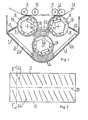
- the developing device comprises a trough-shaped reservoir 1 with two sloping walls 2 and 3 which lie in planes which are intersecting at the bottom side 4 of the reservoir.
- a first developing roller 5 and a second developing roller 6 are installed with their shafts in parallel to each other and to the line of intersection of the sloping walls.
- Either of these developing rollers comprises a non-magnetizable metal cylinder 7, 8 which is rotatable in the direction of the arrow.
- the cylinders of the developing rollers rotate out of each other at the side which is turned away from the bottom of the reservoir.
- each developing roller 7 8 At that side and near each developing roller two guide rollers 9, 10, 11 and 12 have been installed, which convey a photoconductive belt 13 past the developing rollers.
- a stationary magnetic system consisting of a hexagonal soft-iron core 14, 15 is installed.
- each core At a side directed towards the photoconductive belt 13 each core is provided over its full length with a recess 16, 17 in which magnet strips have been installed. On these magnet strips a second layer of magnet strips has been installed. All these magnet strips_have their south pole directed outwards.
- the first developing roller 5 seen against the direction of rotation of the enveloping cylinder, the following three sides of the core are provided with magnet strips, directed outwards with the north-, north- and south pole respectively.
- a magnet with a south pole directed outwards is indicated with an S and a magnet with a north pole directed outwards is indicated with an N.
- a transport roller 18 is installed with the shaft 25 in parallel to the shafts of the developing rollers.
- this transport roller comprises a rotatable, non-magnetizable cylinder and a stationary magnet system consisting of a soft-iron core with hexagonal section which at four successive sides is provided with magnet strips and is directed towards the developing rollers with the two magnet-free sides. The magnet strips are directed outwards alternately with the north- and south pole.
- the cylinder of the transport roller rotates in the same direction as the second developing roller 6 and opposite to the first developing roller 5, as indicated by the arrow-direction.
- the transport roller 18 transports developing powder from the reservoir 1 to the space between the two developing rollers where the developing powder is picked up by the developing rollers.
- a scraper 19, 20 is installed near each developing roller, which scraper extends in length- direction over the whole cylinder surface of the developing roller and which limits the layer-thickness of the developing powder on the developing roller.
- a plate-shaped scraper 21, 22 is installed on each developing roller, which scraper extends in length- direction of the pertaining developing roller over the whole surface of the cylinder of this roller.
- Each scraper extends in the other direction from the pertaining developing roller up to the top side of the nearest sloping wall 2, 3.
- Both sloping walls are provided with groups of parallel partitions 23, 24 which are installed perpendicularly to the sloping wall and extend from the top side of the sloping wall to the lower part of the reservoir. All partitions on the one sloping wall 2 make a sharp angle with the shaft 25 of the transport roller, which is not represented in Fig. 2, and with the shafts of the developing rollers. Seen in the same direction, the partitions on the other sloping wall 3 make an obtuse angle with the shaft 25 of the transport roller and with the shafts of the developing rollers installed in parallel to these.
- the developing powder which falls downwards from the scrapers is deflected from the direction of falling into the direction of the ends of the trough-shaped reservoir, in such a way that the deflection on the one sloping wall is directed to the one end and the deflection on the other sloping wall is directed to the other end.
- the developing powder may sometimes accumulate at one end of the reservoir, for instance when the reservoir is not installed horizontally.
- the partitions on each sloping wall are divided in two groups, in such a way that seen in the same direction each first group has a smaller sharp respectively smaller obtuse angle with the shafts of the transport roller and the developing rollers than the second group.
- the first group of partitions of the one sloping wall makes an angle of 66° with the shaft of the transport roller and the second group on the same wall makes an angle of 73° with the shaft of the transport roller.
- the angles which the first and second group make with the shaft of the transport roller are 107° and 114 0 respectively.
- the first developing roller 5 is provided with two north poles beside each other.
- the order south-north-south-north for the position of the magnet poles directed outwards can be applied in the corresponding developing roller, but in that case a layer of toner can be transferred electrostatically to the cylinder of the developing roller, when developing with binary toner and simultaneous application of a high bias voltage between the photoconductive belt and the developing roller is applied. In this way the developing current and consequently the optical density of the developed image, may start decreasing.
- the layer formed is again whiped away from the developing roller by the developing powder which is supplied between the developing rollers.
Landscapes
- Physics & Mathematics (AREA)
- General Physics & Mathematics (AREA)
- Magnetic Brush Developing In Electrophotography (AREA)
- Dry Development In Electrophotography (AREA)
Applications Claiming Priority (2)
| Application Number | Priority Date | Filing Date | Title |
|---|---|---|---|
| NL7709230 | 1977-08-22 | ||
| NL7709230A NL7709230A (nl) | 1977-08-22 | 1977-08-22 | Inrichting voor het ontwikkelen van ladings- beelden met behulp van magneetborstels. |
Publications (2)
| Publication Number | Publication Date |
|---|---|
| EP0000964A1 true EP0000964A1 (de) | 1979-03-07 |
| EP0000964B1 EP0000964B1 (de) | 1981-11-11 |
Family
ID=19829044
Family Applications (1)
| Application Number | Title | Priority Date | Filing Date |
|---|---|---|---|
| EP78200120A Expired EP0000964B1 (de) | 1977-08-22 | 1978-07-27 | Vorrichtung zur Entwicklung eines elektrostatischen Ladungsbildes mittels Magnetbürsten. |
Country Status (5)
| Country | Link |
|---|---|
| US (1) | US4235193A (de) |
| EP (1) | EP0000964B1 (de) |
| JP (1) | JPS5435741A (de) |
| DE (1) | DE2861312D1 (de) |
| NL (1) | NL7709230A (de) |
Cited By (2)
| Publication number | Priority date | Publication date | Assignee | Title |
|---|---|---|---|---|
| EP0017582A1 (de) * | 1979-04-04 | 1980-10-15 | EASTMAN KODAK COMPANY (a New Jersey corporation) | Einen teilweise leitenden Entwickler verwendendes verbessertes elektrographisches Entwicklungsverfahren |
| US20200043965A1 (en) * | 2015-06-18 | 2020-02-06 | Sony Corporation | Module, method for manufacturing module, and electronic device |
Families Citing this family (10)
| Publication number | Priority date | Publication date | Assignee | Title |
|---|---|---|---|---|
| NL7709230A (nl) * | 1977-08-22 | 1977-12-30 | Oce Van Der Grinten Nv | Inrichting voor het ontwikkelen van ladings- beelden met behulp van magneetborstels. |
| JPS55111974A (en) * | 1979-02-21 | 1980-08-29 | Ricoh Co Ltd | Dry type developing device |
| DE3010647A1 (de) * | 1980-03-20 | 1981-10-01 | Agfa-Gevaert Ag, 5090 Leverkusen | Entwicklungseinrichtung fuer ein elektrofotografisches kopiergeraet |
| FR2521069A2 (fr) * | 1982-02-11 | 1983-08-12 | Cii Honeywell Bull | Dispositif pour l'application de particules solides sur le support d'enregistrement d'une imprimante non-impact |
| US4671207A (en) * | 1985-12-11 | 1987-06-09 | Eastman Kodak Company | Magnetic brush development apparatus |
| JP2938904B2 (ja) * | 1988-12-19 | 1999-08-25 | 株式会社リコー | 現像装置 |
| US5385801A (en) * | 1990-07-12 | 1995-01-31 | Minolta Camera Kabushiki Kaisha | Method of developing electrostatic latent image |
| JP3221195B2 (ja) * | 1993-12-03 | 2001-10-22 | 日立工機株式会社 | 電子写真装置の現像装置 |
| US5495319A (en) * | 1994-06-06 | 1996-02-27 | Hewlett-Packard Company | Developing housing having a plurality of angled ribs |
| US6055401A (en) * | 1995-09-12 | 2000-04-25 | Fujitsu Limited | Electrophotographic image-forming apparatus having developing device which includes a plurality of developing rollers |
Citations (2)
| Publication number | Priority date | Publication date | Assignee | Title |
|---|---|---|---|---|
| NL7709230A (nl) * | 1977-08-22 | 1977-12-30 | Oce Van Der Grinten Nv | Inrichting voor het ontwikkelen van ladings- beelden met behulp van magneetborstels. |
| NL7709899A (nl) * | 1977-02-17 | 1978-08-21 | Siemens Ag | Inrichting voor het ontwikkelen van, op een tus- sendrager opgebrachte ladingsbeelden met behulp van een ontwikkelmengsel. |
Family Cites Families (1)
| Publication number | Priority date | Publication date | Assignee | Title |
|---|---|---|---|---|
| US4131357A (en) * | 1977-03-21 | 1978-12-26 | Xerox Corporation | Sequentially activated development system for an electrophotographic printer |
-
1977
- 1977-08-22 NL NL7709230A patent/NL7709230A/xx not_active Application Discontinuation
-
1978
- 1978-07-07 JP JP8282678A patent/JPS5435741A/ja active Pending
- 1978-07-27 DE DE7878200120T patent/DE2861312D1/de not_active Expired
- 1978-07-27 EP EP78200120A patent/EP0000964B1/de not_active Expired
- 1978-08-11 US US05/933,111 patent/US4235193A/en not_active Expired - Lifetime
Patent Citations (2)
| Publication number | Priority date | Publication date | Assignee | Title |
|---|---|---|---|---|
| NL7709899A (nl) * | 1977-02-17 | 1978-08-21 | Siemens Ag | Inrichting voor het ontwikkelen van, op een tus- sendrager opgebrachte ladingsbeelden met behulp van een ontwikkelmengsel. |
| NL7709230A (nl) * | 1977-08-22 | 1977-12-30 | Oce Van Der Grinten Nv | Inrichting voor het ontwikkelen van ladings- beelden met behulp van magneetborstels. |
Non-Patent Citations (1)
| Title |
|---|
| RESEARCH DISCLOSURE, no. 155, March 1977, HAVANT (GB) J.O. WILLIAMS: "Magnetic brush developing apparatus" pages 28-29 * |
Cited By (2)
| Publication number | Priority date | Publication date | Assignee | Title |
|---|---|---|---|---|
| EP0017582A1 (de) * | 1979-04-04 | 1980-10-15 | EASTMAN KODAK COMPANY (a New Jersey corporation) | Einen teilweise leitenden Entwickler verwendendes verbessertes elektrographisches Entwicklungsverfahren |
| US20200043965A1 (en) * | 2015-06-18 | 2020-02-06 | Sony Corporation | Module, method for manufacturing module, and electronic device |
Also Published As
| Publication number | Publication date |
|---|---|
| JPS5435741A (en) | 1979-03-16 |
| EP0000964B1 (de) | 1981-11-11 |
| NL7709230A (nl) | 1977-12-30 |
| DE2861312D1 (en) | 1982-01-14 |
| US4235193A (en) | 1980-11-25 |
Similar Documents
| Publication | Publication Date | Title |
|---|---|---|
| US3003462A (en) | Apparatus for applying developer powder to photo-conductive insulating sheets | |
| US4266868A (en) | Multiple roll developing apparatus | |
| EP0000964B1 (de) | Vorrichtung zur Entwicklung eines elektrostatischen Ladungsbildes mittels Magnetbürsten. | |
| US3654902A (en) | Toner unit for photoelectrostatic reproduction | |
| EP0625734B1 (de) | Verfahren und Vorrichtung zur Entwicklung eines elektrostatischen Bildes mit einem Zweikomponentenentwickler | |
| US4261290A (en) | Electrostatic developing apparatus having a developer powder mixing device | |
| US4436055A (en) | Developing apparatus | |
| JPH0815981A (ja) | 多極磁気シール | |
| US4041903A (en) | Developing device for use in electrophotography | |
| US4431296A (en) | Developing method and apparatus therefor | |
| US3865080A (en) | Toner pickoff apparatus | |
| US4008686A (en) | Developing device for use in electrophotography | |
| US4266503A (en) | Apparatus for forming a cloud of toner particles | |
| US3911865A (en) | Toner pickoff apparatus | |
| US3855969A (en) | Quality control of electrostatic image developer mix | |
| US3988816A (en) | Magnet roller for electrostatic record developing device | |
| US4068623A (en) | Magnetic feed system for developer mix | |
| EP0025671B1 (de) | Apparat zum Entwickeln eines elektrostatischen latenten Bildes | |
| US4350432A (en) | Development apparatus for developing latent electrostatic images | |
| JPH0254289A (ja) | 画像形成装置 | |
| US4924270A (en) | Toner supply device for use in image forming apparatus | |
| US4532531A (en) | Electrographic recording apparatus | |
| JPH08286503A (ja) | 現像装置 | |
| GB2025796A (en) | Developing Apparatus | |
| JPH0245867Y2 (de) |
Legal Events
| Date | Code | Title | Description |
|---|---|---|---|
| PUAI | Public reference made under article 153(3) epc to a published international application that has entered the european phase |
Free format text: ORIGINAL CODE: 0009012 |
|
| AK | Designated contracting states |
Designated state(s): DE FR GB NL |
|
| 17P | Request for examination filed | ||
| GRAA | (expected) grant |
Free format text: ORIGINAL CODE: 0009210 |
|
| AK | Designated contracting states |
Designated state(s): DE FR GB NL |
|
| REF | Corresponds to: |
Ref document number: 2861312 Country of ref document: DE Date of ref document: 19820114 |
|
| PGFP | Annual fee paid to national office [announced via postgrant information from national office to epo] |
Ref country code: NL Payment date: 19830731 Year of fee payment: 6 |
|
| PGFP | Annual fee paid to national office [announced via postgrant information from national office to epo] |
Ref country code: FR Payment date: 19840615 Year of fee payment: 7 |
|
| PGFP | Annual fee paid to national office [announced via postgrant information from national office to epo] |
Ref country code: DE Payment date: 19840622 Year of fee payment: 7 |
|
| PG25 | Lapsed in a contracting state [announced via postgrant information from national office to epo] |
Ref country code: NL Effective date: 19850201 |
|
| NLV4 | Nl: lapsed or anulled due to non-payment of the annual fee | ||
| GBPC | Gb: european patent ceased through non-payment of renewal fee | ||
| PG25 | Lapsed in a contracting state [announced via postgrant information from national office to epo] |
Ref country code: FR Free format text: LAPSE BECAUSE OF NON-PAYMENT OF DUE FEES Effective date: 19860328 |
|
| PG25 | Lapsed in a contracting state [announced via postgrant information from national office to epo] |
Ref country code: DE Effective date: 19860402 |
|
| REG | Reference to a national code |
Ref country code: FR Ref legal event code: ST |
|
| PG25 | Lapsed in a contracting state [announced via postgrant information from national office to epo] |
Ref country code: GB Effective date: 19881117 |
|
| PLBE | No opposition filed within time limit |
Free format text: ORIGINAL CODE: 0009261 |
|
| STAA | Information on the status of an ep patent application or granted ep patent |
Free format text: STATUS: NO OPPOSITION FILED WITHIN TIME LIMIT |