EP0001048A1 - Procédé et installation de désinfection pour une salle d'opération chirurgicale - Google Patents
Procédé et installation de désinfection pour une salle d'opération chirurgicale Download PDFInfo
- Publication number
- EP0001048A1 EP0001048A1 EP78100593A EP78100593A EP0001048A1 EP 0001048 A1 EP0001048 A1 EP 0001048A1 EP 78100593 A EP78100593 A EP 78100593A EP 78100593 A EP78100593 A EP 78100593A EP 0001048 A1 EP0001048 A1 EP 0001048A1
- Authority
- EP
- European Patent Office
- Prior art keywords
- disinfectant
- air
- room
- air conditioning
- conditioning system
- Prior art date
- Legal status (The legal status is an assumption and is not a legal conclusion. Google has not performed a legal analysis and makes no representation as to the accuracy of the status listed.)
- Granted
Links
- 238000000034 method Methods 0.000 title claims abstract description 78
- 230000000249 desinfective effect Effects 0.000 title claims abstract description 9
- 230000008569 process Effects 0.000 title claims description 19
- 238000004378 air conditioning Methods 0.000 claims abstract description 115
- 238000011144 upstream manufacturing Methods 0.000 claims abstract description 10
- 238000011045 prefiltration Methods 0.000 claims abstract description 8
- 239000000645 desinfectant Substances 0.000 claims description 172
- 239000003570 air Substances 0.000 claims description 158
- WSFSSNUMVMOOMR-UHFFFAOYSA-N Formaldehyde Chemical compound O=C WSFSSNUMVMOOMR-UHFFFAOYSA-N 0.000 claims description 53
- 238000004659 sterilization and disinfection Methods 0.000 claims description 29
- 239000003795 chemical substances by application Substances 0.000 claims description 25
- 230000003472 neutralizing effect Effects 0.000 claims description 22
- 230000002349 favourable effect Effects 0.000 claims description 16
- 239000000203 mixture Substances 0.000 claims description 16
- 239000012080 ambient air Substances 0.000 claims description 11
- 238000011010 flushing procedure Methods 0.000 claims description 8
- 238000010438 heat treatment Methods 0.000 claims description 6
- 230000036961 partial effect Effects 0.000 claims description 6
- ZIBGPFATKBEMQZ-UHFFFAOYSA-N triethylene glycol Chemical compound OCCOCCOCCO ZIBGPFATKBEMQZ-UHFFFAOYSA-N 0.000 claims description 6
- 238000001816 cooling Methods 0.000 claims description 5
- 230000009471 action Effects 0.000 claims description 4
- 239000007864 aqueous solution Substances 0.000 claims description 4
- 125000002485 formyl group Chemical class [H]C(*)=O 0.000 claims description 4
- 238000002156 mixing Methods 0.000 claims description 4
- 239000002904 solvent Substances 0.000 claims description 4
- 230000033228 biological regulation Effects 0.000 claims description 2
- 230000001172 regenerating effect Effects 0.000 claims description 2
- 150000001875 compounds Chemical class 0.000 claims 1
- 239000004020 conductor Substances 0.000 claims 1
- 238000002360 preparation method Methods 0.000 description 24
- 239000007789 gas Substances 0.000 description 14
- 244000052616 bacterial pathogen Species 0.000 description 11
- QGZKDVFQNNGYKY-UHFFFAOYSA-N Ammonia Chemical compound N QGZKDVFQNNGYKY-UHFFFAOYSA-N 0.000 description 9
- 230000000694 effects Effects 0.000 description 8
- 230000002829 reductive effect Effects 0.000 description 8
- LFQSCWFLJHTTHZ-UHFFFAOYSA-N Ethanol Chemical compound CCO LFQSCWFLJHTTHZ-UHFFFAOYSA-N 0.000 description 6
- IAYPIBMASNFSPL-UHFFFAOYSA-N Ethylene oxide Chemical group C1CO1 IAYPIBMASNFSPL-UHFFFAOYSA-N 0.000 description 6
- 238000013461 design Methods 0.000 description 6
- KWGKDLIKAYFUFQ-UHFFFAOYSA-M lithium chloride Chemical compound [Li+].[Cl-] KWGKDLIKAYFUFQ-UHFFFAOYSA-M 0.000 description 6
- 239000000243 solution Substances 0.000 description 6
- 239000010935 stainless steel Substances 0.000 description 6
- 229910001220 stainless steel Inorganic materials 0.000 description 6
- 238000009833 condensation Methods 0.000 description 5
- 230000005494 condensation Effects 0.000 description 5
- 238000010276 construction Methods 0.000 description 5
- 238000001704 evaporation Methods 0.000 description 5
- CURLTUGMZLYLDI-UHFFFAOYSA-N Carbon dioxide Chemical compound O=C=O CURLTUGMZLYLDI-UHFFFAOYSA-N 0.000 description 4
- 229910021529 ammonia Inorganic materials 0.000 description 4
- 238000004140 cleaning Methods 0.000 description 4
- XLYOFNOQVPJJNP-UHFFFAOYSA-N water Substances O XLYOFNOQVPJJNP-UHFFFAOYSA-N 0.000 description 4
- LYCAIKOWRPUZTN-UHFFFAOYSA-N Ethylene glycol Chemical compound OCCO LYCAIKOWRPUZTN-UHFFFAOYSA-N 0.000 description 3
- OKKJLVBELUTLKV-UHFFFAOYSA-N Methanol Chemical compound OC OKKJLVBELUTLKV-UHFFFAOYSA-N 0.000 description 3
- 238000010521 absorption reaction Methods 0.000 description 3
- 230000008901 benefit Effects 0.000 description 3
- 230000005540 biological transmission Effects 0.000 description 3
- 230000008859 change Effects 0.000 description 3
- 239000007795 chemical reaction product Substances 0.000 description 3
- 238000005260 corrosion Methods 0.000 description 3
- 230000007797 corrosion Effects 0.000 description 3
- 238000009826 distribution Methods 0.000 description 3
- 230000008020 evaporation Effects 0.000 description 3
- 210000001503 joint Anatomy 0.000 description 3
- WSFSSNUMVMOOMR-NJFSPNSNSA-N methanone Chemical compound O=[14CH2] WSFSSNUMVMOOMR-NJFSPNSNSA-N 0.000 description 3
- 230000001105 regulatory effect Effects 0.000 description 3
- 238000003860 storage Methods 0.000 description 3
- 231100000331 toxic Toxicity 0.000 description 3
- 230000002588 toxic effect Effects 0.000 description 3
- BGJSXRVXTHVRSN-UHFFFAOYSA-N 1,3,5-trioxane Chemical compound C1OCOCO1 BGJSXRVXTHVRSN-UHFFFAOYSA-N 0.000 description 2
- MHAJPDPJQMAIIY-UHFFFAOYSA-N Hydrogen peroxide Chemical compound OO MHAJPDPJQMAIIY-UHFFFAOYSA-N 0.000 description 2
- 239000000654 additive Substances 0.000 description 2
- 230000000844 anti-bacterial effect Effects 0.000 description 2
- 229910002092 carbon dioxide Inorganic materials 0.000 description 2
- 239000001569 carbon dioxide Substances 0.000 description 2
- 230000003749 cleanliness Effects 0.000 description 2
- 230000001276 controlling effect Effects 0.000 description 2
- VKYKSIONXSXAKP-UHFFFAOYSA-N hexamethylenetetramine Chemical compound C1N(C2)CN3CN1CN2C3 VKYKSIONXSXAKP-UHFFFAOYSA-N 0.000 description 2
- 239000007788 liquid Substances 0.000 description 2
- 229910052751 metal Inorganic materials 0.000 description 2
- 239000002184 metal Substances 0.000 description 2
- 238000006386 neutralization reaction Methods 0.000 description 2
- 231100000252 nontoxic Toxicity 0.000 description 2
- 230000003000 nontoxic effect Effects 0.000 description 2
- 239000011148 porous material Substances 0.000 description 2
- 238000001556 precipitation Methods 0.000 description 2
- 230000009467 reduction Effects 0.000 description 2
- 238000007789 sealing Methods 0.000 description 2
- 230000003068 static effect Effects 0.000 description 2
- 239000000126 substance Substances 0.000 description 2
- 238000009736 wetting Methods 0.000 description 2
- IJGRMHOSHXDMSA-UHFFFAOYSA-N Atomic nitrogen Chemical compound N#N IJGRMHOSHXDMSA-UHFFFAOYSA-N 0.000 description 1
- 241000894006 Bacteria Species 0.000 description 1
- 239000004604 Blowing Agent Substances 0.000 description 1
- 239000004338 Dichlorodifluoromethane Substances 0.000 description 1
- 229910001335 Galvanized steel Inorganic materials 0.000 description 1
- 201000005505 Measles Diseases 0.000 description 1
- 241001465754 Metazoa Species 0.000 description 1
- 101100345589 Mus musculus Mical1 gene Proteins 0.000 description 1
- CBENFWSGALASAD-UHFFFAOYSA-N Ozone Chemical compound [O-][O+]=O CBENFWSGALASAD-UHFFFAOYSA-N 0.000 description 1
- 229930040373 Paraformaldehyde Natural products 0.000 description 1
- 206010035664 Pneumonia Diseases 0.000 description 1
- 206010039587 Scarlet Fever Diseases 0.000 description 1
- 238000009825 accumulation Methods 0.000 description 1
- 239000002253 acid Substances 0.000 description 1
- 230000000996 additive effect Effects 0.000 description 1
- 238000003915 air pollution Methods 0.000 description 1
- 239000010425 asbestos Substances 0.000 description 1
- 238000000429 assembly Methods 0.000 description 1
- 230000000712 assembly Effects 0.000 description 1
- QVGXLLKOCUKJST-UHFFFAOYSA-N atomic oxygen Chemical compound [O] QVGXLLKOCUKJST-UHFFFAOYSA-N 0.000 description 1
- 230000015572 biosynthetic process Effects 0.000 description 1
- 239000004568 cement Substances 0.000 description 1
- 238000006243 chemical reaction Methods 0.000 description 1
- 239000011248 coating agent Substances 0.000 description 1
- 238000000576 coating method Methods 0.000 description 1
- 238000011109 contamination Methods 0.000 description 1
- 239000002826 coolant Substances 0.000 description 1
- 230000008878 coupling Effects 0.000 description 1
- 238000010168 coupling process Methods 0.000 description 1
- 238000005859 coupling reaction Methods 0.000 description 1
- 238000000354 decomposition reaction Methods 0.000 description 1
- PXBRQCKWGAHEHS-UHFFFAOYSA-N dichlorodifluoromethane Chemical compound FC(F)(Cl)Cl PXBRQCKWGAHEHS-UHFFFAOYSA-N 0.000 description 1
- 235000019404 dichlorodifluoromethane Nutrition 0.000 description 1
- 231100000676 disease causative agent Toxicity 0.000 description 1
- 238000006073 displacement reaction Methods 0.000 description 1
- 238000001035 drying Methods 0.000 description 1
- 239000000428 dust Substances 0.000 description 1
- 230000003670 easy-to-clean Effects 0.000 description 1
- 238000005516 engineering process Methods 0.000 description 1
- 230000007613 environmental effect Effects 0.000 description 1
- 238000002474 experimental method Methods 0.000 description 1
- 238000004880 explosion Methods 0.000 description 1
- 239000002360 explosive Substances 0.000 description 1
- 238000001914 filtration Methods 0.000 description 1
- 239000003205 fragrance Substances 0.000 description 1
- 239000008397 galvanized steel Substances 0.000 description 1
- 239000004312 hexamethylene tetramine Substances 0.000 description 1
- 235000010299 hexamethylene tetramine Nutrition 0.000 description 1
- 239000012535 impurity Substances 0.000 description 1
- 208000015181 infectious disease Diseases 0.000 description 1
- 230000002458 infectious effect Effects 0.000 description 1
- 239000000463 material Substances 0.000 description 1
- 238000005259 measurement Methods 0.000 description 1
- 239000007769 metal material Substances 0.000 description 1
- TZIHFWKZFHZASV-UHFFFAOYSA-N methyl formate Chemical compound COC=O TZIHFWKZFHZASV-UHFFFAOYSA-N 0.000 description 1
- 238000012986 modification Methods 0.000 description 1
- 230000004048 modification Effects 0.000 description 1
- JCXJVPUVTGWSNB-UHFFFAOYSA-N nitrogen dioxide Inorganic materials O=[N]=O JCXJVPUVTGWSNB-UHFFFAOYSA-N 0.000 description 1
- 235000015097 nutrients Nutrition 0.000 description 1
- 239000001301 oxygen Substances 0.000 description 1
- 229910052760 oxygen Inorganic materials 0.000 description 1
- 239000003973 paint Substances 0.000 description 1
- 229920002866 paraformaldehyde Polymers 0.000 description 1
- 239000002245 particle Substances 0.000 description 1
- 230000035515 penetration Effects 0.000 description 1
- 239000004033 plastic Substances 0.000 description 1
- 229920000642 polymer Polymers 0.000 description 1
- 239000000843 powder Substances 0.000 description 1
- 239000003755 preservative agent Substances 0.000 description 1
- 230000002335 preservative effect Effects 0.000 description 1
- 239000000047 product Substances 0.000 description 1
- 230000001681 protective effect Effects 0.000 description 1
- 238000010926 purge Methods 0.000 description 1
- 230000009257 reactivity Effects 0.000 description 1
- 238000011084 recovery Methods 0.000 description 1
- 230000029058 respiratory gaseous exchange Effects 0.000 description 1
- 229910052895 riebeckite Inorganic materials 0.000 description 1
- 230000003584 silencer Effects 0.000 description 1
- 229920002379 silicone rubber Polymers 0.000 description 1
- 239000004945 silicone rubber Substances 0.000 description 1
- 239000010802 sludge Substances 0.000 description 1
- 239000007921 spray Substances 0.000 description 1
- 230000000087 stabilizing effect Effects 0.000 description 1
- 229910052717 sulfur Inorganic materials 0.000 description 1
- 230000001629 suppression Effects 0.000 description 1
- NGCMLEQSKQCTAK-UHFFFAOYSA-N tetraoxane Chemical compound C1COOOO1 NGCMLEQSKQCTAK-UHFFFAOYSA-N 0.000 description 1
- 238000005406 washing Methods 0.000 description 1
- 239000002351 wastewater Substances 0.000 description 1
Images

Classifications
-
- F—MECHANICAL ENGINEERING; LIGHTING; HEATING; WEAPONS; BLASTING
- F24—HEATING; RANGES; VENTILATING
- F24F—AIR-CONDITIONING; AIR-HUMIDIFICATION; VENTILATION; USE OF AIR CURRENTS FOR SCREENING
- F24F8/00—Treatment, e.g. purification, of air supplied to human living or working spaces otherwise than by heating, cooling, humidifying or drying
- F24F8/20—Treatment, e.g. purification, of air supplied to human living or working spaces otherwise than by heating, cooling, humidifying or drying by sterilisation
- F24F8/24—Treatment, e.g. purification, of air supplied to human living or working spaces otherwise than by heating, cooling, humidifying or drying by sterilisation using sterilising media
-
- F—MECHANICAL ENGINEERING; LIGHTING; HEATING; WEAPONS; BLASTING
- F24—HEATING; RANGES; VENTILATING
- F24F—AIR-CONDITIONING; AIR-HUMIDIFICATION; VENTILATION; USE OF AIR CURRENTS FOR SCREENING
- F24F8/00—Treatment, e.g. purification, of air supplied to human living or working spaces otherwise than by heating, cooling, humidifying or drying
- F24F8/20—Treatment, e.g. purification, of air supplied to human living or working spaces otherwise than by heating, cooling, humidifying or drying by sterilisation
- F24F8/24—Treatment, e.g. purification, of air supplied to human living or working spaces otherwise than by heating, cooling, humidifying or drying by sterilisation using sterilising media
- F24F8/26—Treatment, e.g. purification, of air supplied to human living or working spaces otherwise than by heating, cooling, humidifying or drying by sterilisation using sterilising media using ozone
-
- Y—GENERAL TAGGING OF NEW TECHNOLOGICAL DEVELOPMENTS; GENERAL TAGGING OF CROSS-SECTIONAL TECHNOLOGIES SPANNING OVER SEVERAL SECTIONS OF THE IPC; TECHNICAL SUBJECTS COVERED BY FORMER USPC CROSS-REFERENCE ART COLLECTIONS [XRACs] AND DIGESTS
- Y02—TECHNOLOGIES OR APPLICATIONS FOR MITIGATION OR ADAPTATION AGAINST CLIMATE CHANGE
- Y02A—TECHNOLOGIES FOR ADAPTATION TO CLIMATE CHANGE
- Y02A50/00—TECHNOLOGIES FOR ADAPTATION TO CLIMATE CHANGE in human health protection, e.g. against extreme weather
- Y02A50/20—Air quality improvement or preservation, e.g. vehicle emission control or emission reduction by using catalytic converters
Definitions
- the invention relates to a method for disinfecting the operating room, which can be air-conditioned by means of an air conditioning system, and, if appropriate, at least one further room in a hospital which can be air-conditioned by means of the same air conditioning system.
- Disinfection of the operating room and / or the preparation room, which is usually connected to the same air conditioning system, is required after each unexpected septic operation. Since then, although continuous operation of the air conditioning system is desirable for safety reasons, the air conditioning system has been shut down, the supply and exhaust air openings in the rooms have been sealed, and the disinfectant, for example formalin, has evaporated in the rooms. After the required exposure time, the disinfectant was removed, in the case of using formalin, for example by additional evaporation of ammonia, which neutralizes the formaldehyde contained in formalin.
- the disinfectant for example formalin
- the invention has for its object a simultaneous disinfection of the operating room and possibly other rooms air-conditioned by means of the same air conditioning system and the channels of the air conditioning system others on the one hand in a simple and safe way.
- the object is achieved according to the invention in a method of the type mentioned in that the air conditioning system is operated in a closed circuit with the room or rooms and that the disinfectant is introduced into a supply air duct of the air conditioning system.
- a simultaneous disinfection of these channels is achieved by the circuit formed during the disinfection process of the gas mixture loaded with the disinfectant through the operating room and possibly other rooms as well as through the air conditioning ducts.
- the for the introduction of the disinfectant and qqf. of the neutralizing agent used devices can be arranged in or on the air conditioning system and thus outside the rooms to be disinfected, so that they can be repaired in the event of their failure without people having to enter the rooms containing the disinfectant.
- the air conditioning system is immediately ready to use to remove any gaseous or vaporizable residues of the disinfectant from the rooms before people can enter them again.
- the temperature and humidity which is most favorable for the effectiveness of the disinfectant can be maintained in the rooms to be disinfected by means of the air conditioning system.
- Formaldehyde which has proven to be very effective, can be used as a disinfectant in a manner known per se.
- Other bactericidal aldehydes can also be used as disinfectants. These must generally be sprayed in an aqueous solution. After the exposure period, the con Densified water can be removed by increasing the supply air temperature and reducing the humidity of the supply air, with some residues of the aldehyde accumulating as sump or sludge at unavoidable sinks in the air conditioning ducts, which could result in corrosion problems when the ducts are built up from sheet metal. However, these can be avoided by using suitable materials, for example asbestos cement, for the ducts. To a large extent, however, aldehydes can be physically absorbed after the end of the exposure time, for example by water washing inside the air conditioning system.
- a surface-active disinfectant is expediently used, which thus disinfects not only the air in the room, but also the inner surfaces of the room or rooms and the surfaces of objects located in the room or rooms.
- One such disinfectant is the formaldehyde already mentioned.
- it may also be sufficient to use only a room disinfectant that is not surface-active.
- Triethylene glycol in particular can be used as an effective room disinfectant. In this case, however, additives can at least partially achieve surface activity if necessary.
- a disinfectant that is effective against all types of germs will be used. In individual cases, however, the use of an agent effective against certain germs may suffice.
- ethylene glycol can be used as a disinfectant, which is between 10 ° C and 27 ° C at 20% to 60% rel.
- Moisture is effective against the causative agents of scarlet fever, measles as well as strep throat and pneumonia.
- Another effective disinfectant is ethylene oxide that can be used neat or in a mixture with methyl format.
- Ethylene oxide is commercially available in spray bottles that contain carbon dioxide or dichlorodifluoromethane as a blowing agent, and can thus be easily sprayed into a duct in the air conditioning system.
- the most favorable concentration during the exposure period is 1000 to 1250 g / m 'of the volume of the rooms to be disinfected and the ducts of the air conditioning system, the relative humidity being 80% to 90% and the temperature should be 30 ° C.
- disinfectants are also conceivable, for example ozone generated by means of an ozonizer, hydrogen peroxide or ethanol with a bactericidal action at concentrations of over 70%.
- the disinfectant is expedient to bring the disinfectant into the supply air duct of the air conditioning system downstream of its cooler in order to prevent the disinfectant from being deposited on the cooler of the air conditioning system, which may still be cold from a previous control intervention.
- the disinfectant is expediently introduced in the vapor state or in the finest possible form.
- the disinfectant used is water-soluble
- the moisture will be increased during the introduction of the disinfectant. This can already be done, at least in part, by introducing an aqueous solution of the disinfectant, as is the case with Verwen is the case of formalin, which is a 35 to 40% aqueous solution of formaldehyde.
- the humidity can be increased by means of the system part of the air conditioning system which serves to control the humidity. For example, the relative humidity of the supply air is expediently kept at over 85% and preferably between 90% and 95% during the introduction of formalin.
- formalin is used as the disinfectant, it expediently contains a stabilizing additive, in particular methanol.
- formaldehyde can also be prepared and introduced in a different way.
- its trioxane or tetroxane oligomers can be decomposed to formaldehyde by heating, with preference given to trioxane because of its lower decomposition temperature.
- Paraformaldehyde can also be depolymerized to formaldehyde by heating to approximately 200 ° C.
- the disinfectant is introduced into the air conditioning ducts until the required disinfectant concentration is present in the rooms to be disinfected. This introduction time is kept as short as possible compared to the required exposure time of the disinfectant.
- the most favorable temperature and humidity conditions for the effect of the disinfectant can be maintained in the rooms to be disinfected by means of the air conditioning system. For example, when using! Formaldehyde this by of approximately 5 g per m 3 of volume of the room or the rooms and the air ducts of the air conditioning system, and then the relative humidity can be kept above 75% and preferably between 80% and 90% during the exposure time.
- the exposure time is approximately 6 hours. If triethylene glycol is used as the disinfectant, this is introduced until a concentration of approximately 6.7 mg per m 'of space is reached, and the exposure time is approximately 1 hour.
- the disinfectant should not condense in the ducts of the air conditioning systems, or at least not in an excessive amount downstream of the point at which it is introduced. It is therefore expedient if, during at least the initial and predominant part of the duration of the introduction of the disinfectant, the gas mixture generated by the introduction, if necessary by heating upstream of the point at which the disinfectant is introduced, is kept at a temperature above the dew point . Since a relatively high temperature is also advantageous for the effectiveness of the disinfectant in most cases, it can be chosen to be relatively high at at least 26 ° C. and preferably 28 ° C. to 31 ° C.
- the air conditioning system must of course be designed for a temperature control range that includes the above-mentioned temperatures by appropriate power measurement of the heater provided therein, whereas otherwise air conditioning systems for operating rooms are usually designed for a temperature control range of 21 ° C to 24 ° C under all possible environmental conditions.
- the room or the rooms is kept at a temperature before the introduction of the disinfectant, if necessary by cooling by means of the air conditioning system.
- be the cute is greater than the dew point of the gas mixture flowing into the room or rooms during the introduction of the disinfectant from the air conditioning system. This ensures that during the application and exposure time, the disinfectant, if necessary together with the introduced solvent, in particular the increased moisture, condenses on the surfaces to be disinfected and wets them completely, thereby accelerating the disinfection process.
- the concentration of the disinfectant in the room or rooms and / or in the channels of the air conditioning system is measured and, if necessary. by feeding at least approximately at the most favorable value for its effectiveness.
- the concentration that was to be achieved when the product was initially introduced can then be reduced to lower values, since this concentration had to be chosen in view of the fact that it was reduced during the exposure time due to condensation and binding of the disinfectant.
- the initial concentration can be reduced by 20% compared to the above-mentioned value of 6.7 mg per m 'of space, but can be kept at least approximately constant during the exposure time by the repeated supply of the disinfectant at intervals.
- a further embodiment of the method is expedient, which consists in that before the disinfectant is introduced by introducing a gas which is inert to the disinfectant, preferably nitrogen or carbon dioxide, the oxygen content of the room air is reduced below the value at which there is a possibility of explosion at the concentration of the disinfectant after the disinfectant has been introduced.
- air conditioning systems for operating theaters are usually designed in such a way that the supply air output outweighs the exhaust air output, so that there is an overpressure in the operating room compared to the surroundings.
- additional rooms for example a preparation room
- the pressure in the additional room or in the additional rooms is lower than in the operating room, but higher than in the rooms and corridors connected to it.
- the air conditioning system can continue to be operated in this usual way, so that there is overpressure in the operating room. In this way, it is advantageously achieved that the disinfectant penetrates any fine cracks and gaps in the inner lining and wall openings, and also reaches germs located here.
- the walls of the operating room and, if applicable, the other rooms as well as the locking devices for the wall openings must be largely gas-tight in order to ensure that the disinfectant, which is also toxic to humans in most cases, penetrates below the overpressure values that occur , for which a corresponding construction effort is required.
- the disinfectant that has penetrated into cracks and crevices under excess pressure partly remains in them after the disinfection process has ended and diffuses out of them only slowly out of them due to the overpressure that continues to prevail in the subsequent air conditioning, which means that even after thorough re-use of the rooms Flushing with fresh air for a long time with traces of the possibly toxic (ethylene oxide) or at least as a disruptive odorant (ethanol) disinfectant is to be expected.
- a pressure which is at most as high as the ambient pressure is maintained in the room or rooms to be disinfected during the duration of the action and preferably also during the introduction of the disinfectant.
- the pressure is the same as the ambient pressure, the disinfectant generally diffuses sufficiently far into cracks and gaps due to its partial pressure which is higher than the atmospheric pressure, in order here, if necessary are sufficient without being difficult to remove or neutralize due to accumulation in cracks and crevices.
- the disinfectant is pressed into the cracks during the overpressure phase.
- the duration of exposure expediently ends with a vacuum phase, since this prepares and facilitates the subsequent removal of the disinfectant.
- the moisture should generally be regulated during the exposure time so that it has the most favorable value for the effectiveness of the disinfectant.
- a range of values of a certain width can usually be specified, within which the moisture can vary without having to accept a noticeable reduction in the disinfectant effect.
- the humidity can usually be adjusted to higher values than the one found to be the most favorable value, without this leading to a noticeable reduction in the disinfectant effect.
- the room or rooms are strongly cooled before the disinfectant is introduced, in order subsequently to condense the disinfectant and possibly its solvent onto the bottom during the introduction and at least during the start of the exposure time to reach the dew point of cooled surfaces, in order to promote this condensation, the humidity can certainly be regulated to high values without the effectiveness of the process suffering or the required exposure time being significantly extended.
- this method is not the most economical if a lower moisture level would suffice for the best possible disinfection effect. In this case, it is rather advisable to regulate the moisture so that the dew point remains below the dew point at the respective temperature of the inside of the room or rooms, as long as this results in the moisture value applicable for the most favorable disinfectant effect is not undercut.
- a warm air flow can be supplied to the interior of such devices in order to keep the above-mentioned parts at a temperature above the dew point, while the moisture is condensed on the other, previously cooled surfaces in the manner already explained. It is particularly expedient to take a partial flow of the gas mixture supplied to the room or rooms from the supply air duct of the air conditioning system, dehumidify it and then heat it up before it is fed into the interior of the device, since this also causes the inner parts of the disinfectant and the neutralizing agent can be exposed, but not exposed to corrosive moisture.
- the removal of the gas mixture from the supply air duct is best carried out immediately upstream of a filter located in this, since the pressure drop occurring at the filter can be used to introduce the gas mixture into the interior of the device at a pressure which is higher than the internal pressure in the room; in general, its housing will have sufficient openings to allow the warm gas mixture to subsequently escape into the surrounding space, while such an opening can also be created if necessary.
- the disinfectant is blown out by supplying fresh air. This is only possible in a simple manner if the disinfectant is non-toxic to humans and animals and is still gaseous at the end of the exposure time or at least has a vapor pressure so high that it can be removed by fresh air in a reasonable time.
- the disinfec tion agent has a toxic effect on humans, it may only be released into the ambient air in small quantities per unit of time and / or in low concentrations, which is why the fresh air supply is increased starting with low values such that the amount of air discharged per unit of time or the Concentration of the disinfectant in the exhaust air initially remains at least approximately constant and has a low value;
- fresh air must be supplied to it, for example via a separate outside air duct with a fan located therein.
- the concentration of ethylene oxide in the exhaust air may not exceed 20 mg / m 3 .
- Another and generally even more favorable method for removing the disinfectant is that it is at least partially physically absorbed, preferably washed out.
- This method is suitable, for example, for removing the highly hygroscopic triethylene glycol and, to a lesser extent, for the water-miscible ethylene oxide.
- the wastewater obtained can then itself be chemically treated by suitable means in order to achieve a content of only such substances, since it can then be safely fed into the sewer system.
- the disinfectant is chemically neutralized;
- Negativeizing in the present context is understood in accordance with the customary use in disinfection technology to mean the implementation of the disinfectant with another agent, the neutralizing agent, in such a way that the reaction product or the reaction products are medically harmless and in particular are non-toxic, so the reaction between a basic agent and an acid is not necessary.
- the neutralizing agent is expediently introduced in gaseous form or as finely atomized as possible, expediently in an air line of the air conditioning system and preferably at the same location as the disinfectant.
- the methods described above can also be used in combination.
- the concentration of the disinfectant can first be reduced by physical absorption, then most of the remaining residue can be bound by chemical neutralization and finally the small remaining remainder can be flushed out by supplying fresh air.
- a flushing with fresh air is expedient in any case if the air conditioning is then carried out with partial use of circulating air in order to remove any remaining disinfectant and / or neutralizing agent.
- the gas mixture supplied to the room or rooms is heated during the removal process, either to facilitate the absorption of the disinfectant in the purge air, either to increase the solubility of the disinfectant in physical absorption, or to improve the reactivity between disinfectant and neutralizing agent.
- the air conditioning system can be operated in a conventional manner in such a way as has already been described for the course of the procedure during the exposure time that the operating room and possibly the preparation room have an overpressure in relation to the environment prevails.
- the air conditioning system can be operated for the duration of the removal of the disinfectant in such a way that there is a negative pressure in the room or rooms with respect to the surroundings, since this may result in Disinfectants contained in existing cracks in the rooms can be more easily evaporated and removed more easily.
- a device for carrying out the method according to the invention is based on the rest of the construction with an air conditioning system, which communicates with the ambient air via an outside air and exhaust air duct and with the operating room and, if appropriate, at least one further room via a supply air and an exhaust air duct is in the supply air duct, a fan, a heater, a cooler, a humidification device, a pre-filter on the suction side and a further filter on the pressure side are switched on, another fan is switched on in the exhaust air line and the outside air duct can be closed airtight to the environment by means of a shut-off device.
- the device is designed such that between the pressure-side section of the exhaust air duct and a mixing chamber formed in the supply air duct between the shut-off device of the outside air duct and the pre-filter there is a bypass that can be shut off in an airtight manner by means of a further shut-off device and that a chamber is located in the supply air duct the disinfectant can be introduced.
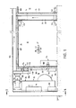
- FIG. 1 shows the air-conditioned operating room 10, which can be disinfected if necessary, and partially an adjacent preparation room 12, which are connected to one another by a passage indicated at 14 behind the drawing plane; the passage can be closed airtight.
- An air conditioning system 16 is provided for air conditioning, which is predominantly accommodated in the air conditioning center 18. This is located on the side of the operating room 10 opposite the preparation room 12, directly adjacent to a wall 20. Between the operating room 10 and the preparation room 12 there is a wall 22 which, on the side of the operating room 10, has an inner lining 24 spaced apart from it in order to be able to accommodate an exhaust air duct 28 (FIGS. 2, 3) between the wall and the inner lining 24. Arrows indicate the current in all figures direction of the air or the gas mixture used in the disinfection process.
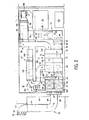
- the air conditioning system 16 comprises an outside air duct 30 and an exhaust air duct 32, via which it is connected to the environment, as well as a supply air duct 34 and the already mentioned exhaust air duct 28, via which it is connected to the operating room 10 and the preparation room 12.
- a control cabinet 36 is provided in the air-conditioning center 18 for controlling all functions of the air conditioning system 16, with corresponding humidity and humidity controls for controlling the humidity and temperature in the operating room 10.
- 37 and 39 and setpoint adjuster, 38 and 40 are arranged.
- a further temperature sensor 41 detects the temperature of the inner surface of the operating room in order to be able to regulate the humidity in such a way that it suffices to achieve the desired condensation during the initial period of the exposure.
- the setpoint adjuster 38, 40 are only effective during the air conditioning; During the entire disinfection process, there is a program control of its sequence, also with regard to temperature and humidity.
- the outside air duct 30 consists of a scraper 42, a muffler 44, a bend 48 passed through the outer wall 46 of the air-conditioning center 18 and a distribution chamber 50.
- a blind 52 is arranged on the input side and a flap shut-off device 54 is arranged behind it. From the distribution chamber 50, the outside air can enter a mixing chamber 58 via two flap arrangements 56 which can be shut off in an airtight manner and with which the supply air duct 34 begins.
- a fan 60 is shuttered in the supply air duct 34 tet.
- the preheater 68 serves to prevent ice formation at low temperatures of the outside air.
- the cooler 78 has an increased cooling capacity compared to the conventional design in air conditioning systems for operating rooms, in order to be able to cool the operating room 10 and the preparation room 12 well below their dew point before the disinfectant solution is introduced.
- the air conditioning system 16 is designed in such a way that the setting range of the temperature to be maintained by it in the operating room 10 and in the preparation room 12 under all ambient conditions extends beyond the usual setting range limit of 2'1 ° C. to lower values.
- the reheater 82 and / or the reheater 84 have, at least when operated together, such a capability that the temperature of the operating room 10 and the preparation room 12 during the exposure time of the disinfectant, despite the previous cooling, in a short time to the most favorable for the effectiveness of the disinfectant , can bring relatively high temperature. They are therefore also more powerful than the re-heaters of conventional air conditioning systems in terms of their heat output.
- a device 90 for introducing a disinfectant, in the exemplary embodiment for evaporating formalin, and a further device 92 for introducing a neutralizing agent, in the exemplary embodiment for evaporating ammonia, are accommodated in chamber 88.
- the devices 90, 92 are arranged centrally in the chamber 88 so that the supply air flows around them on all sides and that the disinfectant or the neutralizing agent gets directly into the supply air.
- a steam humidifier 94 is provided above the chamber 88. From here, the supply air passes through a silencer 96, an airtight shut-off flap arrangement 98, an arc section 100 and a flow meter 102 into two branch channels 104, 106 an intermediate ceiling 107 (FIG. 1) of the intermediate space 10 and the wall 22 into an intermediate space which lies above the intermediate ceiling 108 of the preparation room 12. Openings (not shown in more detail) are provided in the false ceiling 108, at which the branch duct 104 opens into the preparation space 12.
- the branch duct 106 of the supply air duct 34 which is located lower than the branch duct 104, runs parallel to the wall 20 separating the air-conditioning center 18 and the operating room 10 within the air-conditioning center 18.
- Four outlet sections 110 extend from the branch duct 106, which pass through the wall 20 and are closed with blinds 112 (Fig. 1) lead covered openings 114 through which the supply air enters the operating room.
- blinds 112 Fig. 1
- the exhaust air from the operating room 10 enters the exhaust air duct 28 via the upper, adjacent to the false ceiling 107 Openings 118 and lower openings 120 located near the floor, which are opposite the supply air openings 114 in the operating room 10.
- In the preparation room 12 there are exhaust air openings 122 connected to the exhaust air duct 28 near the floor. All exhaust air openings 118, 120, 122 are covered with suspended matter filter mats 124 in order to make it more difficult for germs to penetrate and, in the event of a disinfection process, to make the germs trapped in the filter mats 124 particularly accessible for the disinfectant.
- the exhaust air duct 28 is guided upwards in the space between the wall 22 and the inner lining 24 adjacent to it and runs in the space above the false ceiling 107 parallel to the branch duct 104 of the supply air duct 34.
- the exhaust air duct 28 is provided with duct sections 126, 128 connected to the heat exchanger 74.
- the exhaust air flowing through this is via a further duct section 130, an exhaust fan 132 and a.
- Double-curved duct section 134 is supplied to the exhaust air duct 32.
- the exhaust air duct 32 comprises a muffler 136 and a duct arch 138 leading into the open, into which an airtight lockable flap arrangement 140 is switched on.
- a bypass 142 is branched off, which comprises a downward curved piece 144, an airtight lockable flap arrangement 146 and a vertical duct section 148, the latter opening into the mixing chamber 58 at its lower end .
- an electromedical device 176 is arranged near the wall 20, which is so heavy that it does not easily ent during a disinfection process could be removed and is therefore left in the operating room 10.
- it will be strongly cooled before the disinfectant is introduced, while the operating room 10 and the preparation room 12 are cooled, and during the exposure time and if necessary, warm air or a heated gas mixture is supplied during the removal of the disinfectant.
- the interior of the device 176 upstream of the suspended matter filter 116 is connected to the end of the branch duct 106 of the Zluit duct 34 via an airtight flap 178, a duct 180, a dehumidifier 182, a heater 184, a pipeline 186 and a detachable pipe coupling 188.
- the duct 180 could also be connected upstream of the chamber 88, for example in FIG. 2 below the filter 86, to the supply air duct 34 in order to dehumidify the gas mixture supplied; to facilitate.
- this supply could also take place while the disinfectant is being introduced, while in the exemplary embodiment described above it is expediently interrupted as long as the disinfectant is introduced and the gas mixture is moistened by means of the humidifier 94.
- the air conditioning system 16 is largely constructed from standardized components and is space-saving in such a way that its components located in the air conditioning center 18 are easily accessible.
- the climate control center 18 is in turn accessible through a door 150 and connected to the environment by means of an exhaust fan 152.
- the flaps are lator 60 sucked in and supplied as supply air to the operating room 10 and the preparation room 12, while the exhaust air is extracted by means of the fan 132 and at least partially discharged via the exhaust air duct 32.
- Energy and moisture recovery is achieved by the heat exchanger 74 in that the exhaust air heats the rotor of the heat exchanger 74, which rotor consists of an inorganic storage mass, and releases the heat and moisture back into the supply air as it circulates, so that optimum efficiency is achieved.
- the heat exchanger 74 can be stopped and the cooler 78 can cool the supply air.
- the coolant of the cooler 78 is cooled by means of a calender 150 which is also arranged in the air-conditioning center 18. If, on the other hand, the temperature control requires the supply air to be heated, this takes place by means of the reheater 82 or the reheater 84. If necessary, the supply air is humidified by means of the steam humidifier 94.
- valve assemblies 56 are closed and the valve assembly 146 in the bypass 142 is fully opened.
- the flap arrangement 140 of the exhaust air duct 32 is closed.
- the air between the operating room 10 and the preparation room 12 on the one hand and the air conditioning system 16 on the other hand is thus guided in a closed circuit, and the disinfection process can be carried out in the manner already described.
- the prefilter 62 is expediently a filter of class B2 or possibly a fine filter of class C according to Walter: "Problems of air pollution when using modern filters", dust cleanliness. 25 (1965), pages 441 to 447.
- the suspended matter filters 64 and 116 and the suspended matter filter mats 124 are expediently high-performance suspended matter filters of class S (DIN 24184), which collect more than 99% of all germs supplied to them.
- the filter 86 can be of class C or, more appropriately, also of class S, as in the exemplary embodiment.
- the large number of high-efficiency filters used means that the interior of the air conditioning system 16 has almost the same level of cleanliness as that during normal air conditioning operation 10 itself. If the operating room 10 is contaminated, the filter mats 124 and the suspended matter filters 64 largely keep germs away from the interior of the air conditioning system 16, so that the air conditioning system is then even less contaminated than the operating room. areas of the air conditioning system 16 should not reach the same extent everywhere as the inner surfaces of the operating room 10.
- Air openings 118 and / or 120 may be formed in a different way.
- the air outlets can also be arranged in the ceiling instead of in a wall.
- the alternating setting of an overpressure and a negative pressure in the operating room 10 and in the preparation room 12 is controlled by means of an interval switching of the programmer control circuit provided in the control cabinet 36 during the exposure time of the disinfectant and during the subsequent removal of the disinfectant.
- the negative pressure is achieved in that the delivery capacity of the supply air blower 60 (FIG. 2) is reduced compared to other operating cases, which Technically, for example, by gate control of thyristors switched into the electrical power supply, it is much easier to implement than, for example, increasing the delivery capacity of the exhaust air fan 132.
- the operating room 10 and the preparation room 12 are provided with the inner lining 24.
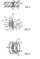
- This is made airtight while avoiding gaps and crevices, namely it consists of a covering of plates, two of which are partially shown in section in FIG. 4.
- These plates 152 lie with a butt joint between adjacent plates in a plane parallel to the respective wall. They are made up of three layers.
- the layer lying towards the room 10 or 12 consists of a stainless steel sheet 154.
- the layer facing the wall consists of a galvanized steel sheet 156.
- Stainless steel sheet 154 and sheet 156 have a mutual distance of 20 mm.
- the cavity between them is foamed with a plastic that forms the middle layer 158.
- the thickness of the stainless steel sheet 154 and the sheet 156 is 1 mm in each case. Overall, this results in a stable structure that requires attachment to only a few attachment points.
- Sealing strips 160 made of silicone rubber run in the butt joints, which ensure an airtight seal.
- the sealing strips 160 have a shape such that they do not dig into an overpressure or underpressure in the spaces 10, 12; in the butt joint they have a fir-tree-like cross section, while they lie on the edge regions of the stainless steel sheets 154 with a widened, band-shaped cross section.
- the stainless steel sheets 154 all hygle nical requirements and in particular easy to clean, they have an additional task in connection with the disinfection process. Because of their good thermal conductivity and because of their thickness made available due to their thickness, they guarantee the condensation of the disinfectant and the moisture after the previous cooling when the disinfectant is introduced, due to the temperature below the dew point. In order to achieve as uniform a wetting as possible, the surface of the stainless steel sheets 154 facing the room is appropriately matted.
- the inner lining of the operating room 10 and the preparation room 12 can also be designed such that it is structurally combined with the parts of the air conditioning ducts behind it, that is to say that the duct sections are lined with the lining of the walls and / or the ceiling is structurally integrated.
- the air outlet and air inlet openings can also be structurally integrated into the lining.
- FIG. 5 shows a partially sectioned, perspective illustration of the rotor 162 of the heat exchanger 74 (FIGS. 1 to 3).
- the rotor consists of inorganic, non-metallic material which has a multiplicity of shafts and through channels 164 formed thereby and which is coated with lithium chloride.
- the exhaust air flows from the duct section 128 through the ducts 164 to the duct section 130, thereby heating the rotor 162 and releasing a large part of its moisture content to the lithium chloride.
- the channels 164 flow through the supply air which flows from the channel section 62 through the rotor 162 to the channel section 76. supply air.
- a lock zone 168 is provided, in which a small proportion of the supply air that has passed through the rotor 162 is collected, deflected in the opposite direction, passed again through the rotor 162 and mixed into the exhaust air flow. This completely prevents exhaust air from entering the supply air flow. In addition, self-cleaning of the rotor from impurities is achieved. As experiments have shown, no nutrient medium for the reproduction of bacteria can develop on the surface coating of the storage mass formed by lithium chloride.
- the lock zone 168 explained can also be dispensed with, since a high degree of purity is already achieved by the other configuration of the air conditioning system 16, as explained above. If the lock zone 168 is dispensed with, both the suspended matter filter 64 and the filter 86 will be designed as high-performance suspended matter filters of the class S.
- FIG. 6 shows the flow meter 102 switched into the supply air duct 34 in more detail. It has a rectifier 170 formed from a drawn hexagonal honeycomb profile, which leaves the supply air with a practically completely uniform speed profile in a laminar, exclusively axially directed flow.
- the rectifier 170 Arranged behind the rectifier 170 are two measuring nozzles 172 for the static pressure near the outer circumference, which are connected to one another in a manner not shown in detail. Furthermore, a plurality of measuring nozzles 174 connected to one another are provided for measuring the total pressure, which are distributed over the entire cross-section. The flow can be determined extremely precisely by forming the difference between the static pressure and the total pressure. This is important both in the air conditioning of the rooms 10, 12 and during the disinfection process.
- both reheaters 82, 84 can be switched on simultaneously. If a disinfectant is used, which can be blown out by flushing with fresh air, the device 92 can be dispensed with, while on the other hand a blower that draws in outside air is expediently provided, which allows fresh air to be mixed in with the exhaust air before being blown out into the environment, in order to increase the concentration of the disinfectant in the exiting exhaust air.
Landscapes
- Engineering & Computer Science (AREA)
- Chemical & Material Sciences (AREA)
- Combustion & Propulsion (AREA)
- Mechanical Engineering (AREA)
- General Engineering & Computer Science (AREA)
- Apparatus For Disinfection Or Sterilisation (AREA)
- Central Air Conditioning (AREA)
Applications Claiming Priority (2)
| Application Number | Priority Date | Filing Date | Title |
|---|---|---|---|
| DE19772740738 DE2740738A1 (de) | 1977-09-09 | 1977-09-09 | Verfahren und einrichtung zum desinfizieren des operationsraumes eines krankenhauses |
| DE2740738 | 1977-09-09 |
Publications (2)
| Publication Number | Publication Date |
|---|---|
| EP0001048A1 true EP0001048A1 (fr) | 1979-03-21 |
| EP0001048B1 EP0001048B1 (fr) | 1980-12-10 |
Family
ID=6018568
Family Applications (1)
| Application Number | Title | Priority Date | Filing Date |
|---|---|---|---|
| EP78100593A Expired EP0001048B1 (fr) | 1977-09-09 | 1978-08-03 | Procédé et installation de désinfection pour une salle d'opération chirurgicale |
Country Status (4)
| Country | Link |
|---|---|
| EP (1) | EP0001048B1 (fr) |
| JP (1) | JPS5450184A (fr) |
| DE (2) | DE2740738A1 (fr) |
| IT (1) | IT1160639B (fr) |
Cited By (1)
| Publication number | Priority date | Publication date | Assignee | Title |
|---|---|---|---|---|
| WO2018153501A1 (fr) * | 2017-02-24 | 2018-08-30 | M. Braun Inertgas-Systeme Gmbh | Dispositif et procédé d'échange d'un gaz présent dans une chambre de travail d'une enceinte à gaz inerte accessible |
Families Citing this family (12)
| Publication number | Priority date | Publication date | Assignee | Title |
|---|---|---|---|---|
| DE3630111A1 (de) * | 1986-09-04 | 1988-03-17 | Hoelter Heinz | Verfahren zur reinigung von belueftungskanaelen vorzugsweise in krankenhaeusern, altenheimen usw. |
| NZ225086A (en) * | 1987-06-22 | 1990-11-27 | Commw Ind Gases | Treatment of air in air conditioning system by adding bactericide |
| JP4426851B2 (ja) | 2002-03-28 | 2010-03-03 | バイオケル ユーケイ リミテッド | 閉じた空間を除染する方法及び装置 |
| JP5484681B2 (ja) * | 2007-03-28 | 2014-05-07 | パナソニックヘルスケア株式会社 | 無菌環境維持装置 |
| GB0710331D0 (en) | 2007-05-30 | 2007-07-11 | Bioquell Uk Ltd | Improved in or relating to methods of decontaminating enclosed spaces |
| JP4922271B2 (ja) * | 2008-09-19 | 2012-04-25 | 株式会社大気社 | 空調対象空間の燻蒸方法 |
| JP5452997B2 (ja) * | 2009-07-02 | 2014-03-26 | 清水建設株式会社 | 室内除染システム |
| DE102010002320A1 (de) * | 2010-02-25 | 2011-08-25 | YIT Germany GmbH, 80992 | Verfahren zur Desinfektion mindestens eines Filterelements einer Filtervorrichtung sowie Filtervorrichtung |
| DE102011052913A1 (de) * | 2011-08-23 | 2013-02-28 | Yit Germany Gmbh | Vorrichtung und Verfahren zur Desinfektion eines Filterelements |
| DE202015104817U1 (de) * | 2015-09-11 | 2015-10-09 | Krones Ag | Vorrichtung zur Bereitstellung von Reinluft in einer Getränkeabfüllanlage |
| JP7349907B2 (ja) * | 2019-12-26 | 2023-09-25 | ライオン株式会社 | 微生物抑制方法及び微生物抑制システム |
| JP2024122285A (ja) * | 2023-02-28 | 2024-09-09 | インテグリカルチャー株式会社 | 殺菌方法及び殺菌システム |
Citations (3)
| Publication number | Priority date | Publication date | Assignee | Title |
|---|---|---|---|---|
| US3493323A (en) * | 1966-10-27 | 1970-02-03 | Demuth Dev Corp The | Method and apparatus for sterilizing the air ducts of air-conditioning systems |
| FR2191908A1 (fr) * | 1972-07-06 | 1974-02-08 | Draegerwerk Ag | |
| DE2308012A1 (de) * | 1973-02-14 | 1974-08-29 | Sulzer Ag | Verfahren und geraet zur desinfektion von lueftungsanlagen |
Family Cites Families (2)
| Publication number | Priority date | Publication date | Assignee | Title |
|---|---|---|---|---|
| BE622106A (fr) * | 1961-09-04 | |||
| DE1930507A1 (de) * | 1969-06-16 | 1970-12-23 | Berthold & Sutter Abtlg Appbau | Verfahren und Vorrichtung zur Erzeugung einer dem Meereskuesten-Klima entsprechenden Luftzusammensetzung |
-
1977
- 1977-09-09 DE DE19772740738 patent/DE2740738A1/de not_active Ceased
-
1978
- 1978-08-03 DE DE7878100593T patent/DE2860298D1/de not_active Expired
- 1978-08-03 EP EP78100593A patent/EP0001048B1/fr not_active Expired
- 1978-09-02 JP JP10802478A patent/JPS5450184A/ja active Pending
- 1978-09-08 IT IT69086/78A patent/IT1160639B/it active
Patent Citations (3)
| Publication number | Priority date | Publication date | Assignee | Title |
|---|---|---|---|---|
| US3493323A (en) * | 1966-10-27 | 1970-02-03 | Demuth Dev Corp The | Method and apparatus for sterilizing the air ducts of air-conditioning systems |
| FR2191908A1 (fr) * | 1972-07-06 | 1974-02-08 | Draegerwerk Ag | |
| DE2308012A1 (de) * | 1973-02-14 | 1974-08-29 | Sulzer Ag | Verfahren und geraet zur desinfektion von lueftungsanlagen |
Cited By (3)
| Publication number | Priority date | Publication date | Assignee | Title |
|---|---|---|---|---|
| WO2018153501A1 (fr) * | 2017-02-24 | 2018-08-30 | M. Braun Inertgas-Systeme Gmbh | Dispositif et procédé d'échange d'un gaz présent dans une chambre de travail d'une enceinte à gaz inerte accessible |
| CN108778538A (zh) * | 2017-02-24 | 2018-11-09 | 布劳恩惰性气体系统有限公司 | 用于从可维修的惰性气体壳体的工作室更换气体的装置和方法 |
| CN108778538B (zh) * | 2017-02-24 | 2021-08-24 | 布劳恩惰性气体系统有限公司 | 用于从可维修的惰性气体壳体的工作室更换气体的装置和方法 |
Also Published As
| Publication number | Publication date |
|---|---|
| IT7869086A0 (it) | 1978-09-08 |
| DE2860298D1 (en) | 1981-02-19 |
| IT1160639B (it) | 1987-03-11 |
| EP0001048B1 (fr) | 1980-12-10 |
| DE2740738A1 (de) | 1979-03-22 |
| JPS5450184A (en) | 1979-04-19 |
Similar Documents
| Publication | Publication Date | Title |
|---|---|---|
| EP0001048B1 (fr) | Procédé et installation de désinfection pour une salle d'opération chirurgicale | |
| DE4308585C2 (de) | Verfahren und Vorrichtung zum Bekämpfen von Schädlingen | |
| EP2025351A1 (fr) | Dispositif de purification d'air doté d'un neutraliseur d'O3 et procédé de purification d'air | |
| DE2721048C2 (de) | Vorrichtung zur Reinigung von Geruchsstoffe enthaltende Abluft | |
| EP3643975A1 (fr) | Dispositif d'aération pour espaces intérieurs des locaux résidentiels et commerciaux | |
| EP2200760B1 (fr) | Dispositif et procédé pour nettoyer des espaces fermés | |
| DE60210273T2 (de) | Anordnung zur steuerung des luftstroms, zum beispiel in reinräumen | |
| EP0687869A2 (fr) | Procédé et dispositif pour exterminer les vermines de l'air | |
| DE20113965U1 (de) | Anlage zur Reinigung von Abluft, Anlage zur Reinigung von Zuluft, Anlage zur Reinigung von Zu- und Abluft und Anlage zur Reinigung von Umluft in Nutztierställen | |
| DE202020101127U1 (de) | Klimatisierungseinrichtung sowie Klimatisierungsmodul dafür | |
| DE102013012268A1 (de) | Verfahren und Vorrichtung zur Verbesserung der Raumluft | |
| DE4011514C1 (fr) | ||
| DE3913076C2 (fr) | ||
| DE202009007256U1 (de) | Trocknungs- und Entkeimungsgerät für Kleider und Sportausrüstungsgegenstände in Behältern | |
| CH698806B1 (de) | Trocknungs- und Entkeimungsgerät für Kleider und Sportausrüstungsgegenstände in Beghältern. | |
| DE102015114555B4 (de) | Verfahren zur Entfeuchtung von saugfähigen Objekten mit gleichzeitiger antimikrobiellen Wirkung sowie ein entsprechendes Gerät zur Umsetzung dieses Verfahrens | |
| DE202010011419U1 (de) | Vorrichtung zur Reinigung von Oberflächen in geschlossenen Räumen | |
| DE10114171C1 (de) | Befeuchtung von Gasen | |
| DE20021658U1 (de) | Gerät zum Reinigen und Klimatisieren von Luft | |
| AT410804B (de) | Beizanlage | |
| AT12509U1 (de) | Vorrichtung zur reinigung von oberflächen in geschlossenen räumen | |
| DE29908532U1 (de) | Lufttechnische Anlage für Garderobenschränke | |
| DE2918670A1 (de) | Vorrichtung fuer kopiergeraete zum sammeln von ammoniakdaempfen | |
| DE8900928U1 (de) | Entfeuchtungsvorrichtung | |
| EP0625678A1 (fr) | Système de conditionnement d'air pour le domaine humain |
Legal Events
| Date | Code | Title | Description |
|---|---|---|---|
| PUAI | Public reference made under article 153(3) epc to a published international application that has entered the european phase |
Free format text: ORIGINAL CODE: 0009012 |
|
| AK | Designated contracting states |
Designated state(s): BE CH DE FR GB LU NL SE |
|
| 17P | Request for examination filed | ||
| GRAA | (expected) grant |
Free format text: ORIGINAL CODE: 0009210 |
|
| AK | Designated contracting states |
Designated state(s): BE CH DE FR GB LU NL SE |
|
| PG25 | Lapsed in a contracting state [announced via postgrant information from national office to epo] |
Ref country code: SE Effective date: 19801210 |
|
| REF | Corresponds to: |
Ref document number: 2860298 Country of ref document: DE Date of ref document: 19810219 |
|
| PG25 | Lapsed in a contracting state [announced via postgrant information from national office to epo] |
Ref country code: NL Effective date: 19810310 |
|
| NLV1 | Nl: lapsed or annulled due to failure to fulfill the requirements of art. 29p and 29m of the patents act | ||
| PG25 | Lapsed in a contracting state [announced via postgrant information from national office to epo] |
Ref country code: LU Free format text: LAPSE BECAUSE OF NON-PAYMENT OF DUE FEES Effective date: 19810831 |
|
| PGFP | Annual fee paid to national office [announced via postgrant information from national office to epo] |
Ref country code: LU Payment date: 19830616 Year of fee payment: 6 |
|
| PGFP | Annual fee paid to national office [announced via postgrant information from national office to epo] |
Ref country code: BE Payment date: 19840630 Year of fee payment: 7 |
|
| PGFP | Annual fee paid to national office [announced via postgrant information from national office to epo] |
Ref country code: DE Payment date: 19840814 Year of fee payment: 7 |
|
| PGFP | Annual fee paid to national office [announced via postgrant information from national office to epo] |
Ref country code: FR Payment date: 19840823 Year of fee payment: 7 |
|
| PGFP | Annual fee paid to national office [announced via postgrant information from national office to epo] |
Ref country code: CH Payment date: 19840903 Year of fee payment: 7 |
|
| PG25 | Lapsed in a contracting state [announced via postgrant information from national office to epo] |
Ref country code: GB Effective date: 19890803 |
|
| PG25 | Lapsed in a contracting state [announced via postgrant information from national office to epo] |
Ref country code: CH Effective date: 19890831 Ref country code: BE Effective date: 19890831 |
|
| BERE | Be: lapsed |
Owner name: STIERLEN-MAQUET A.G. Effective date: 19890831 |
|
| GBPC | Gb: european patent ceased through non-payment of renewal fee | ||
| PG25 | Lapsed in a contracting state [announced via postgrant information from national office to epo] |
Ref country code: FR Effective date: 19900427 |
|
| REG | Reference to a national code |
Ref country code: CH Ref legal event code: PL |
|
| PG25 | Lapsed in a contracting state [announced via postgrant information from national office to epo] |
Ref country code: DE Effective date: 19900501 |
|
| REG | Reference to a national code |
Ref country code: FR Ref legal event code: ST |
|
| PLBE | No opposition filed within time limit |
Free format text: ORIGINAL CODE: 0009261 |
|
| STAA | Information on the status of an ep patent application or granted ep patent |
Free format text: STATUS: NO OPPOSITION FILED WITHIN TIME LIMIT |