EP0001111A1 - Procédé et dispositif de fabrication de pellicules soufflées - Google Patents
Procédé et dispositif de fabrication de pellicules soufflées Download PDFInfo
- Publication number
- EP0001111A1 EP0001111A1 EP78100829A EP78100829A EP0001111A1 EP 0001111 A1 EP0001111 A1 EP 0001111A1 EP 78100829 A EP78100829 A EP 78100829A EP 78100829 A EP78100829 A EP 78100829A EP 0001111 A1 EP0001111 A1 EP 0001111A1
- Authority
- EP
- European Patent Office
- Prior art keywords
- film
- point
- film bubble
- bubble
- extruder nozzle
- Prior art date
- Legal status (The legal status is an assumption and is not a legal conclusion. Google has not performed a legal analysis and makes no representation as to the accuracy of the status listed.)
- Granted
Links
- 238000000034 method Methods 0.000 title claims abstract description 22
- 238000004519 manufacturing process Methods 0.000 title abstract description 14
- 238000001816 cooling Methods 0.000 claims description 15
- 238000010096 film blowing Methods 0.000 claims description 13
- 238000007664 blowing Methods 0.000 claims description 6
- 239000011888 foil Substances 0.000 claims description 6
- 230000001105 regulatory effect Effects 0.000 claims description 5
- 238000001125 extrusion Methods 0.000 claims description 4
- 238000005070 sampling Methods 0.000 claims 1
- 230000004888 barrier function Effects 0.000 description 8
- 239000002994 raw material Substances 0.000 description 6
- 239000000155 melt Substances 0.000 description 4
- 230000033228 biological regulation Effects 0.000 description 3
- 238000011161 development Methods 0.000 description 3
- 230000000694 effects Effects 0.000 description 3
- 239000004698 Polyethylene Substances 0.000 description 2
- 230000007423 decrease Effects 0.000 description 2
- 230000006866 deterioration Effects 0.000 description 2
- 238000002474 experimental method Methods 0.000 description 2
- 239000000463 material Substances 0.000 description 2
- 239000000289 melt material Substances 0.000 description 2
- -1 polyethylene Polymers 0.000 description 2
- 229920000573 polyethylene Polymers 0.000 description 2
- 206010009192 Circulatory collapse Diseases 0.000 description 1
- 240000003517 Elaeocarpus dentatus Species 0.000 description 1
- 241000196324 Embryophyta Species 0.000 description 1
- 230000015572 biosynthetic process Effects 0.000 description 1
- 239000003054 catalyst Substances 0.000 description 1
- 239000007795 chemical reaction product Substances 0.000 description 1
- 238000010276 construction Methods 0.000 description 1
- 230000001276 controlling effect Effects 0.000 description 1
- 238000013461 design Methods 0.000 description 1
- 238000010438 heat treatment Methods 0.000 description 1
- 238000012423 maintenance Methods 0.000 description 1
- 238000005259 measurement Methods 0.000 description 1
- 238000012544 monitoring process Methods 0.000 description 1
- 230000003287 optical effect Effects 0.000 description 1
- 238000005457 optimization Methods 0.000 description 1
- 238000006116 polymerization reaction Methods 0.000 description 1
- 239000007787 solid Substances 0.000 description 1
- 230000006641 stabilisation Effects 0.000 description 1
- 238000011105 stabilization Methods 0.000 description 1
- 239000013589 supplement Substances 0.000 description 1
- 238000004804 winding Methods 0.000 description 1
Images


Classifications
-
- B—PERFORMING OPERATIONS; TRANSPORTING
- B29—WORKING OF PLASTICS; WORKING OF SUBSTANCES IN A PLASTIC STATE IN GENERAL
- B29C—SHAPING OR JOINING OF PLASTICS; SHAPING OF MATERIAL IN A PLASTIC STATE, NOT OTHERWISE PROVIDED FOR; AFTER-TREATMENT OF THE SHAPED PRODUCTS, e.g. REPAIRING
- B29C48/00—Extrusion moulding, i.e. expressing the moulding material through a die or nozzle which imparts the desired form; Apparatus therefor
- B29C48/03—Extrusion moulding, i.e. expressing the moulding material through a die or nozzle which imparts the desired form; Apparatus therefor characterised by the shape of the extruded material at extrusion
- B29C48/09—Articles with cross-sections having partially or fully enclosed cavities, e.g. pipes or channels
- B29C48/10—Articles with cross-sections having partially or fully enclosed cavities, e.g. pipes or channels flexible, e.g. blown foils
-
- B—PERFORMING OPERATIONS; TRANSPORTING
- B29—WORKING OF PLASTICS; WORKING OF SUBSTANCES IN A PLASTIC STATE IN GENERAL
- B29C—SHAPING OR JOINING OF PLASTICS; SHAPING OF MATERIAL IN A PLASTIC STATE, NOT OTHERWISE PROVIDED FOR; AFTER-TREATMENT OF THE SHAPED PRODUCTS, e.g. REPAIRING
- B29C48/00—Extrusion moulding, i.e. expressing the moulding material through a die or nozzle which imparts the desired form; Apparatus therefor
- B29C48/25—Component parts, details or accessories; Auxiliary operations
- B29C48/92—Measuring, controlling or regulating
-
- B—PERFORMING OPERATIONS; TRANSPORTING
- B29—WORKING OF PLASTICS; WORKING OF SUBSTANCES IN A PLASTIC STATE IN GENERAL
- B29C—SHAPING OR JOINING OF PLASTICS; SHAPING OF MATERIAL IN A PLASTIC STATE, NOT OTHERWISE PROVIDED FOR; AFTER-TREATMENT OF THE SHAPED PRODUCTS, e.g. REPAIRING
- B29C2948/00—Indexing scheme relating to extrusion moulding
- B29C2948/92—Measuring, controlling or regulating
- B29C2948/92009—Measured parameter
- B29C2948/92114—Dimensions
- B29C2948/92123—Diameter or circumference
-
- B—PERFORMING OPERATIONS; TRANSPORTING
- B29—WORKING OF PLASTICS; WORKING OF SUBSTANCES IN A PLASTIC STATE IN GENERAL
- B29C—SHAPING OR JOINING OF PLASTICS; SHAPING OF MATERIAL IN A PLASTIC STATE, NOT OTHERWISE PROVIDED FOR; AFTER-TREATMENT OF THE SHAPED PRODUCTS, e.g. REPAIRING
- B29C2948/00—Indexing scheme relating to extrusion moulding
- B29C2948/92—Measuring, controlling or regulating
- B29C2948/92009—Measured parameter
- B29C2948/92114—Dimensions
- B29C2948/92133—Width or height
-
- B—PERFORMING OPERATIONS; TRANSPORTING
- B29—WORKING OF PLASTICS; WORKING OF SUBSTANCES IN A PLASTIC STATE IN GENERAL
- B29C—SHAPING OR JOINING OF PLASTICS; SHAPING OF MATERIAL IN A PLASTIC STATE, NOT OTHERWISE PROVIDED FOR; AFTER-TREATMENT OF THE SHAPED PRODUCTS, e.g. REPAIRING
- B29C2948/00—Indexing scheme relating to extrusion moulding
- B29C2948/92—Measuring, controlling or regulating
- B29C2948/92323—Location or phase of measurement
- B29C2948/92428—Calibration, after-treatment, or cooling zone
-
- B—PERFORMING OPERATIONS; TRANSPORTING
- B29—WORKING OF PLASTICS; WORKING OF SUBSTANCES IN A PLASTIC STATE IN GENERAL
- B29C—SHAPING OR JOINING OF PLASTICS; SHAPING OF MATERIAL IN A PLASTIC STATE, NOT OTHERWISE PROVIDED FOR; AFTER-TREATMENT OF THE SHAPED PRODUCTS, e.g. REPAIRING
- B29C2948/00—Indexing scheme relating to extrusion moulding
- B29C2948/92—Measuring, controlling or regulating
- B29C2948/92504—Controlled parameter
- B29C2948/9258—Velocity
- B29C2948/926—Flow or feed rate
-
- B—PERFORMING OPERATIONS; TRANSPORTING
- B29—WORKING OF PLASTICS; WORKING OF SUBSTANCES IN A PLASTIC STATE IN GENERAL
- B29C—SHAPING OR JOINING OF PLASTICS; SHAPING OF MATERIAL IN A PLASTIC STATE, NOT OTHERWISE PROVIDED FOR; AFTER-TREATMENT OF THE SHAPED PRODUCTS, e.g. REPAIRING
- B29C2948/00—Indexing scheme relating to extrusion moulding
- B29C2948/92—Measuring, controlling or regulating
- B29C2948/92504—Controlled parameter
- B29C2948/92609—Dimensions
- B29C2948/92619—Diameter or circumference
-
- B—PERFORMING OPERATIONS; TRANSPORTING
- B29—WORKING OF PLASTICS; WORKING OF SUBSTANCES IN A PLASTIC STATE IN GENERAL
- B29C—SHAPING OR JOINING OF PLASTICS; SHAPING OF MATERIAL IN A PLASTIC STATE, NOT OTHERWISE PROVIDED FOR; AFTER-TREATMENT OF THE SHAPED PRODUCTS, e.g. REPAIRING
- B29C2948/00—Indexing scheme relating to extrusion moulding
- B29C2948/92—Measuring, controlling or regulating
- B29C2948/92504—Controlled parameter
- B29C2948/92609—Dimensions
- B29C2948/92628—Width or height
-
- B—PERFORMING OPERATIONS; TRANSPORTING
- B29—WORKING OF PLASTICS; WORKING OF SUBSTANCES IN A PLASTIC STATE IN GENERAL
- B29C—SHAPING OR JOINING OF PLASTICS; SHAPING OF MATERIAL IN A PLASTIC STATE, NOT OTHERWISE PROVIDED FOR; AFTER-TREATMENT OF THE SHAPED PRODUCTS, e.g. REPAIRING
- B29C2948/00—Indexing scheme relating to extrusion moulding
- B29C2948/92—Measuring, controlling or regulating
- B29C2948/92504—Controlled parameter
- B29C2948/92704—Temperature
-
- B—PERFORMING OPERATIONS; TRANSPORTING
- B29—WORKING OF PLASTICS; WORKING OF SUBSTANCES IN A PLASTIC STATE IN GENERAL
- B29C—SHAPING OR JOINING OF PLASTICS; SHAPING OF MATERIAL IN A PLASTIC STATE, NOT OTHERWISE PROVIDED FOR; AFTER-TREATMENT OF THE SHAPED PRODUCTS, e.g. REPAIRING
- B29C2948/00—Indexing scheme relating to extrusion moulding
- B29C2948/92—Measuring, controlling or regulating
- B29C2948/92819—Location or phase of control
- B29C2948/92923—Calibration, after-treatment or cooling zone
Definitions
- the invention relates to a film blowing process in which a film tube is produced by extrusion and expanded by internal overpressure to form a film bubble, which initially expands increasingly from a point of smallest diameter and reaches a point of maximum diameter via a turning point, in order then to be flattened.
- the setting and maintenance of stable process conditions is a crucial problem.
- the quality and uniformity of the film produced depend, for example, on the choice and composition of the catalyst components, the polymerization medium, the pressure, the temperature, the extrusion speed and the design of the extruder and the extrusion nozzle.
- the combination of suitable values of these influencing variables always results in stable operation only within a limited tolerance range. In practice, these tolerances are exceeded relatively often, particularly in the production of paper-like films from high-molecular low-pressure polyethylene, so that machine downtimes or the production of inferior quality often occur in the production of such films.
- the object of the invention is to monitor the stability state of the film bubble in the known film blowing method of the type mentioned in order to be able to counteract an impending deterioration in the film quality in good time by taking appropriate countermeasures, and on the other hand to be the cheapest choice for different types of machines and / or melt materials to determine the process parameters based on the shape of the film bubble.
- the invention provides that the width of the film bubble is monitored at a first measuring point between the point of inflection and the point of maximum diameter.
- the invention is based on the idea that the various, in some cases very complex, process parameters, in total together with the right choice result in an optimal shape of the film bubble.
- the blister is relatively stable and thus ensures a uniform and reproducible film production. It is important to recognize that changes in any parameter that lead to a deterioration in the film quality initially affect the shape of the blister. Since the film bubble is generated directly after the extruder, compliance with the. Any deviations in the shape of the film bubble were recognized immediately, so that a system can be used to counteract the further deviation of the film bubble from its optimal shape. Another decisive factor is the fact that a change in the shape of the film bubble primarily affects the area between the inflection point and the maximum value, provided that the film bubble passes through a ring or the like which determines its final size.
- a common cause of errors is, for example, the drop in bladder pressure.
- the bubble diameter decreases most in the area between the point of inflection and the point of maximum diameter. If such a change is detected, the amount of blown air can be increased.
- the diameter of the film bubble as a function of the length of the film bubble follows a fairly good approximation of a third degree equation which has two maxima and one inflection point.
- the areas between the upper maximum and the inflection point and the area between the lower maximum and the inflection point are particularly sensitive to changes in the process parameters, and their ver Runs or deviations from the ideal curve provide information about impending instabilities.
- the amount of cooling air which is blown against the film tube from the outside is regulated depending on the width of the film bubble determined at the second measuring point.
- the amount of external cooling air is of great importance for the process. It is extremely critical and its influence on the shape of the film bubble is often non-linear.
- the invention further relates to a film blowing device with an annular extruder nozzle which has a blowing air outlet, at least one ring arranged at a distance from the extruder nozzle for fixing the film bubble, and with a flat-laying and take-off device arranged behind the ring.
- a scanning device is arranged at the first measuring point between the point of inflection of the film bubble and the point of maximum diameter, which monitors the radial expansion of the film bubble and / or the distance of P from the extruder nozzle.
- the scanner must have no effect on the shape of the film bubble.
- An optical scanning device consisting of one or more light barriers is preferably used,
- the melt material is fed into an extruder 10 which contains an extruder screw (not shown) and a heating device.
- the melt is fed to the blow head 11, which has an annular extruder nozzle from which the hose 12 emerges.
- Support air is supplied to the hose through the blow head 11.
- the blow head 11 is from. surround a cooling ring 13, to which cooling air is supplied by a fan 14. The cooling air is blown against the hose 12 from the outside.
- the hose 12 After the hose 12 has traveled a certain distance, it widens to form the hose bladder 15, the diameter of which is approximately twice to four times the hose diameter.
- the hose bladder runs through the guide 16, which consists of two support rings 161 and 162, in which it is fixed to the final dimension, and is then folded flat.
- the support ring .161 which faces the extruder nozzle, has a considerably greater length than the subsequent support ring 162 ..
- Side guides 17, 18, which diverge or converge in the transport direction of the film and which feed the film hose to a pair of nip rollers 19, are used to fold the film tube.
- the folded film tube is then wound onto a drum 23.
- the support ring 162, the side guides 17, 18, the pair of nip rollers 19 and the take-up drum 23 are mounted on a turntable 21 which rotates slowly about its vertical axis.
- FIG. 2 shows some curves of the projected film bubble that result from changing individual influencing variables.
- the location 31 of minimum diameter, the turning point 32 and location 33 of maximum diameter are shown on the solid curve 30.
- the bladder diameter is reduced slightly behind the point 33: before the hose enters the ring 16.
- the radius of the film tube at the die gap is denoted by d / 2 and the bladder radius in the ring 16 by D / 2.
- the ring 16 fixes the bubble diameter and contributes to the constancy of the film dimension.
- a bubble shape of curve 35 in which there is no pronounced minimum value at all, shows particularly poor film strength in the transverse direction.
- a bubble shape of curve 30 has been found to be quite unstable. The formation of such a bubble shape must be counteracted as far as possible.
- the curves were drawn in a coordinate system whose X-axis is in the plane of the final shape, i.e. at the beginning of the ring 16, and whose Y axis coincides with the axis of symmetry of the hose or the film bubble.
- a scanning device in the form of a light barrier 36 is shown, which is arranged in the area between the inflection point 32 and the point 33 of maximum diameter.
- the contour of this film bubble is designated 37.
- the light barrier 36 is attached to this film bubble in such a way that the light beam emanating from the light source 38 and directed onto the photocell 39 is just interrupted by the film bubble. This means that no readjustment of the procedure is necessary. If air squeezes occur on the squeeze rollers or on the feed line or in the material of the film bubble, the diameter of the film bubble is reduced.
- the Light barrier 36 is released and the corresponding signal is used via a relay and a solenoid valve with throttle for the metered refilling of the amount of supporting air blown into the hose.
- a relay and a solenoid valve with throttle for the metered refilling of the amount of supporting air blown into the hose.
- the light source 38 and the photocell 39 are attached to a rail 40 which is fastened in an adjustable manner and can be moved towards the film bubble in the manner described after the optimal film bubble has been set.
- the lay-flat and take-off device is slowly rotated with respect to the extruder nozzle. Either the lay-flat and take-off device can be rotated and the extruder nozzle can be arranged in a fixed manner, as shown in FIG. 1, or vice versa. If such a rotating system is used, then the light barrier 36 should be arranged in a manner fixed against relative rotation to the extruder nozzle. When the extruder nozzle rotates, the light cabinets should also rotate.
- the two rings 161 and 162 serve to fix the bladder diameter, of which the longer ring 161 is non-rotatably connected to the extruder nozzle and the other ring 162 is non-rotatably connected to the lay-flat and take-off device. In this way, it is prevented that imperfections in the film, which result in the area of the ejection and removal device, can have effects in the area of the light barrier.
- the rings 161 and 162 can be designed as adjustable iris diaphragms. If necessary, even more rings can be arranged one behind the other.
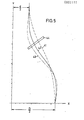
- FIG. 5 shows in a representation similar to that of FIG. 2 the influence of the amount of cooling air blown against the film tube by the cooling ring 13 on the shape of the film bubble.
- the film bubble initially had the shape 41 shown in dashed lines. without a pronounced minimum change. Starting from this shape, the amount of cooling air was changed, so that the bubble shape shown as a solid line-42 resulted, which has a smaller diameter in the initial area-of the film bubble than in curve 41 and has a more pronounced maximum area than this.
- curve 43 shown in dash-dot lines, suddenly appeared, at which the maximum value and minimum value compared to curve 42 are still increased.
- the shape of the film bubble returned to curve 42.
- a change in the cooling air quantity does not necessarily have to result in a change in the shape of the film bubble with a certain tendency, but can have very different effects.
- a light band 44 from a series of photocells can be arranged in the manner shown in FIG. 5 in the area between the turning point and the minimum value of the hose diameter, and as perpendicular as possible to the family of possible curves.
- Those photocells that are covered by the tubular bladder indicate the control amplitude, while the sign with which the control intervention is to take place depends on whether the point in question was occupied by enlarging or reducing the size of the bladder.
- any change in shape of the film bubble can be determined by the method according to the invention and, depending on this, the regulation of a suitable process parameter can be carried out. All measurable quantities of pressure, temperature, quantity and time can be assigned to the graph using process computers. Values from examinations of the raw material and the finished film can supplement the figures.
- the method according to the invention is also suitable for the selection of raw materials with regard to the desired end product.
- Another area of application is the development of new types of raw materials, in which the method according to the invention contributes to achieving comparable and reproducible results.
Landscapes
- Engineering & Computer Science (AREA)
- Mechanical Engineering (AREA)
- Shaping By String And By Release Of Stress In Plastics And The Like (AREA)
- Extrusion Moulding Of Plastics Or The Like (AREA)
Applications Claiming Priority (2)
| Application Number | Priority Date | Filing Date | Title |
|---|---|---|---|
| DE19772740629 DE2740629A1 (de) | 1977-09-09 | 1977-09-09 | Folienblasverfahren |
| DE2740629 | 1977-09-09 |
Publications (2)
| Publication Number | Publication Date |
|---|---|
| EP0001111A1 true EP0001111A1 (fr) | 1979-03-21 |
| EP0001111B1 EP0001111B1 (fr) | 1981-01-07 |
Family
ID=6018508
Family Applications (1)
| Application Number | Title | Priority Date | Filing Date |
|---|---|---|---|
| EP78100829A Expired EP0001111B1 (fr) | 1977-09-09 | 1978-09-06 | Procédé et dispositif de fabrication de pellicules soufflées |
Country Status (3)
| Country | Link |
|---|---|
| US (1) | US4201741A (fr) |
| EP (1) | EP0001111B1 (fr) |
| DE (2) | DE2740629A1 (fr) |
Cited By (2)
| Publication number | Priority date | Publication date | Assignee | Title |
|---|---|---|---|---|
| EP0074526A1 (fr) * | 1981-08-24 | 1983-03-23 | Gloucester Engineering Co., Inc. | Commande de la dimension d'une feuille extrudée-soufflée |
| EP0522278A1 (fr) * | 1991-07-08 | 1993-01-13 | WindmÀ¶ller & Hölscher | Procédé de réglage du diamètre des films tubulaires fabriqués dans une installation d'extrusion-soufflage |
Families Citing this family (14)
| Publication number | Priority date | Publication date | Assignee | Title |
|---|---|---|---|---|
| US4402656A (en) * | 1978-11-30 | 1983-09-06 | Gloucester Engineering Co., Inc. | Control of tubular film size |
| US4355966A (en) * | 1981-05-04 | 1982-10-26 | E. B. Westlake, Jr. | Automatic control of bubble size in blown film |
| US4663097A (en) * | 1984-08-15 | 1987-05-05 | Imperial Chemical Industries, Plc. | Method and apparatus for controlling dynamic instability in axially moving form |
| DE8501177U1 (de) * | 1985-01-18 | 1986-05-22 | Alpine Ag, 8900 Augsburg | Abzugsvorrichtung für Kunststoff-Schlauchfolien |
| DE4118122A1 (de) * | 1991-06-03 | 1992-12-10 | Windmoeller & Hoelscher | Verfahren zur bestimmung und/oder regelung des orientierungsgrades von in blasfolienanlagen hergestellten schlauchfolien |
| US5756041A (en) * | 1991-07-11 | 1998-05-26 | Arruda; William C. | Method and apparatus for processing blown tube films |
| US5310329A (en) * | 1992-02-05 | 1994-05-10 | Cree Robert E | Air shroud device for a blown film extrusion line |
| US6254368B1 (en) * | 1992-04-20 | 2001-07-03 | Tomy Machinery Manufacturing Col., Ltd. | Plastic molding machine |
| US5470216A (en) * | 1993-04-05 | 1995-11-28 | Nippon Petrochmicals Company, Limited | Film manufacturing apparatus with bubble controlling sensor |
| US6447278B1 (en) | 1998-05-26 | 2002-09-10 | Polymer Processing, Inc. | Apparatus for processing blown tube films |
| DE19911978C2 (de) * | 1999-03-17 | 2002-09-05 | Windmoeller & Hoelscher | Vorrichtung zum Erwärmen einer zwischen einem Vorzugsrollenpaar und einem Abzugsrollenpaar zu einer Schlauchfolienblase aufgeblasenen Schlauchfolienbahn |
| US9090005B2 (en) | 2012-04-02 | 2015-07-28 | Velcro Industries B.V. | Blown film fastening |
| US20130318752A1 (en) | 2012-05-31 | 2013-12-05 | Velcro Industries B.V. | Releasable fastenings with barriers |
| CN115384886B (zh) * | 2022-08-31 | 2023-11-21 | 广东美房智高机器人有限公司 | 一种套袋工装及套袋方法 |
Citations (5)
| Publication number | Priority date | Publication date | Assignee | Title |
|---|---|---|---|---|
| DE917033C (de) * | 1952-02-06 | 1954-08-23 | Hermann Berstorff Maschb Ansta | Einrichtung zum Aufblasen des aus einer Schneckenpresse austretenden Schlauches aus warmformbarem Kunststoff |
| US3400184A (en) * | 1964-09-21 | 1968-09-03 | Exxon Research Engineering Co | Process and apparatus for preparing film from thermoplastic resins |
| DE2043129A1 (en) * | 1969-10-03 | 1971-04-22 | Lentia Gmbh | Photoelectric monitor for diameter of - blown tube |
| US3650644A (en) * | 1967-02-10 | 1972-03-21 | Bemberg Ag | Apparatus for biaxially stretching thermoplastic tubular film |
| DE2461720A1 (de) * | 1973-12-28 | 1975-07-10 | Inst For Ind Res & Standards | Vorrichtung zur steuerung der breite einer materialbahn |
Family Cites Families (5)
| Publication number | Priority date | Publication date | Assignee | Title |
|---|---|---|---|---|
| NL302747A (fr) * | 1963-02-11 | 1900-01-01 | ||
| DE1504039A1 (de) * | 1965-03-01 | 1969-09-25 | Barmag Barmer Maschf | Vorrichtung zum Flachlegen und Kuehlen eines nahtlosen thermoplastischen Folienschlauches vor dessen Eintritt in den Abquetschwalzenspalt einer Extrusionsanlage |
| US3932080A (en) * | 1972-02-15 | 1976-01-13 | Showa Denko Kabushiki Kaisha | Apparatus for manufacture of tubular film from thermoplastic resin |
| US4101614A (en) * | 1975-03-03 | 1978-07-18 | The Dow Chemical Company | Blown film process |
| US4140460A (en) * | 1977-09-01 | 1979-02-20 | Egan Machinery Company | Control of blown film tube diameter |
-
1977
- 1977-09-09 DE DE19772740629 patent/DE2740629A1/de not_active Withdrawn
-
1978
- 1978-09-01 US US05/938,773 patent/US4201741A/en not_active Expired - Lifetime
- 1978-09-06 EP EP78100829A patent/EP0001111B1/fr not_active Expired
- 1978-09-06 DE DE7878100829T patent/DE2860422D1/de not_active Expired
Patent Citations (5)
| Publication number | Priority date | Publication date | Assignee | Title |
|---|---|---|---|---|
| DE917033C (de) * | 1952-02-06 | 1954-08-23 | Hermann Berstorff Maschb Ansta | Einrichtung zum Aufblasen des aus einer Schneckenpresse austretenden Schlauches aus warmformbarem Kunststoff |
| US3400184A (en) * | 1964-09-21 | 1968-09-03 | Exxon Research Engineering Co | Process and apparatus for preparing film from thermoplastic resins |
| US3650644A (en) * | 1967-02-10 | 1972-03-21 | Bemberg Ag | Apparatus for biaxially stretching thermoplastic tubular film |
| DE2043129A1 (en) * | 1969-10-03 | 1971-04-22 | Lentia Gmbh | Photoelectric monitor for diameter of - blown tube |
| DE2461720A1 (de) * | 1973-12-28 | 1975-07-10 | Inst For Ind Res & Standards | Vorrichtung zur steuerung der breite einer materialbahn |
Cited By (2)
| Publication number | Priority date | Publication date | Assignee | Title |
|---|---|---|---|---|
| EP0074526A1 (fr) * | 1981-08-24 | 1983-03-23 | Gloucester Engineering Co., Inc. | Commande de la dimension d'une feuille extrudée-soufflée |
| EP0522278A1 (fr) * | 1991-07-08 | 1993-01-13 | WindmÀ¶ller & Hölscher | Procédé de réglage du diamètre des films tubulaires fabriqués dans une installation d'extrusion-soufflage |
Also Published As
| Publication number | Publication date |
|---|---|
| DE2740629A1 (de) | 1979-03-15 |
| US4201741A (en) | 1980-05-06 |
| DE2860422D1 (en) | 1981-02-26 |
| EP0001111B1 (fr) | 1981-01-07 |
Similar Documents
| Publication | Publication Date | Title |
|---|---|---|
| EP0001111B1 (fr) | Procédé et dispositif de fabrication de pellicules soufflées | |
| DE3816777A1 (de) | Verfahren zur steuerung eines papieraufrollers | |
| DE3628201A1 (de) | Verfahren und vorrichtung zur ausbildung einer schlauchfolie | |
| DE2754096C2 (fr) | ||
| EP0224435B1 (fr) | Procédé de fabrication d'une nappe de filaments continus et appareil pour la mise en oeuvre du procédé | |
| DE102016119872A1 (de) | Verfahren und Vorrichtung zur Regelung der Formstabilität eines Folienschlauchs bei dessen Herstellung mittels einer Blasfolienextrusionsanlage | |
| EP4442427A1 (fr) | Installation de soufflage de film et procédé de réglage d'une installation de soufflage de film | |
| EP0894895A2 (fr) | Procédé et dispositif de détection et de correction des changements du profil transversal d'orientation des fibres | |
| CH591322A5 (fr) | ||
| DE102019215492B4 (de) | Blasfolienanlage und Verfahren zur Herstellung von Folienschläuchen oder Folienbahnen | |
| DE3731961C2 (fr) | ||
| DE10125480A1 (de) | Verfahren und Vorrichtung zur Herstellung eines Multifilament-Garns aus einem thermoplastischen Polymer | |
| EP0586630B1 (fr) | Procede et dispositif de fabrication de filaments synthetiques continus | |
| DE3885469T2 (de) | Vorrichtung und verfahren zur herstellung gestreckter filme. | |
| EP0553367B1 (fr) | Appareil pour la fabrication de pellicules tubulaires | |
| DE69324635T2 (de) | Verfahren und Vorrichtung zur Herstellung von Blasfolien | |
| DE102016012424A1 (de) | Verfahren zum Betreiben einer Blasfolienanlage, Verwendung eines Verfahrens zum Betreiben einer Blasfolienanlage, Blasfolienanlage und Abquetschwalze | |
| EP1188539B1 (fr) | Purge d'une filière de soufflage | |
| EP0693357B1 (fr) | Procédé de moulage de corps creux en matière thermoplastique par extrusion soufflage | |
| DE202023101698U1 (de) | Folienblasanlage | |
| CH432813A (de) | Verfahren und Vorrichtung zum Kühlen von rohrförmigen thermoplastischen Folien | |
| EP0536685B1 (fr) | Dispositif pour perforer, en relation avec la qualité du matériel, des bandes de formulaires | |
| DE102020127189A1 (de) | Blasfolienanlage, Verfahren zum Herstellen einer Blasfolienbahn und damit hergestellte Folie | |
| DE102019121959B4 (de) | Verfahren zur Herstellung einer Kunststoff-Folie | |
| EP3954527A1 (fr) | Procédé de fabrication d'un film en matière plastique |
Legal Events
| Date | Code | Title | Description |
|---|---|---|---|
| PUAI | Public reference made under article 153(3) epc to a published international application that has entered the european phase |
Free format text: ORIGINAL CODE: 0009012 |
|
| AK | Designated contracting states |
Designated state(s): BE CH DE FR GB LU NL SE |
|
| 17P | Request for examination filed | ||
| GRAA | (expected) grant |
Free format text: ORIGINAL CODE: 0009210 |
|
| AK | Designated contracting states |
Designated state(s): BE CH DE FR GB LU NL SE |
|
| REF | Corresponds to: |
Ref document number: 2860422 Country of ref document: DE Date of ref document: 19810226 |
|
| PG25 | Lapsed in a contracting state [announced via postgrant information from national office to epo] |
Ref country code: LU Free format text: LAPSE BECAUSE OF NON-PAYMENT OF DUE FEES Effective date: 19810930 |
|
| PGFP | Annual fee paid to national office [announced via postgrant information from national office to epo] |
Ref country code: SE Payment date: 19830930 Year of fee payment: 6 Ref country code: NL Payment date: 19830930 Year of fee payment: 6 |
|
| PG25 | Lapsed in a contracting state [announced via postgrant information from national office to epo] |
Ref country code: SE Effective date: 19840907 |
|
| PG25 | Lapsed in a contracting state [announced via postgrant information from national office to epo] |
Ref country code: NL Effective date: 19850401 |
|
| NLV4 | Nl: lapsed or anulled due to non-payment of the annual fee | ||
| PGFP | Annual fee paid to national office [announced via postgrant information from national office to epo] |
Ref country code: LU Payment date: 19890308 Year of fee payment: 11 |
|
| PGFP | Annual fee paid to national office [announced via postgrant information from national office to epo] |
Ref country code: FR Payment date: 19890309 Year of fee payment: 11 |
|
| PGFP | Annual fee paid to national office [announced via postgrant information from national office to epo] |
Ref country code: CH Payment date: 19890313 Year of fee payment: 11 |
|
| PGFP | Annual fee paid to national office [announced via postgrant information from national office to epo] |
Ref country code: GB Payment date: 19890331 Year of fee payment: 11 |
|
| PGFP | Annual fee paid to national office [announced via postgrant information from national office to epo] |
Ref country code: BE Payment date: 19890414 Year of fee payment: 11 |
|
| PGFP | Annual fee paid to national office [announced via postgrant information from national office to epo] |
Ref country code: DE Payment date: 19890523 Year of fee payment: 11 |
|
| PG25 | Lapsed in a contracting state [announced via postgrant information from national office to epo] |
Ref country code: GB Effective date: 19890906 |
|
| PG25 | Lapsed in a contracting state [announced via postgrant information from national office to epo] |
Ref country code: CH Effective date: 19890930 Ref country code: BE Effective date: 19890930 |
|
| BERE | Be: lapsed |
Owner name: PANNENBECKER HEINRICH Effective date: 19890930 |
|
| GBPC | Gb: european patent ceased through non-payment of renewal fee | ||
| PG25 | Lapsed in a contracting state [announced via postgrant information from national office to epo] |
Ref country code: FR Effective date: 19900531 |
|
| REG | Reference to a national code |
Ref country code: CH Ref legal event code: PL |
|
| PG25 | Lapsed in a contracting state [announced via postgrant information from national office to epo] |
Ref country code: DE Effective date: 19900601 |
|
| REG | Reference to a national code |
Ref country code: FR Ref legal event code: ST |
|
| EUG | Se: european patent has lapsed |
Ref document number: 78100829.7 Effective date: 19850617 |
|
| PLBE | No opposition filed within time limit |
Free format text: ORIGINAL CODE: 0009261 |
|
| STAA | Information on the status of an ep patent application or granted ep patent |
Free format text: STATUS: NO OPPOSITION FILED WITHIN TIME LIMIT |