EP0001155A1 - Système d'inspection de pipeline comprenant un vehicule muni de moyens de controle de sa vitesse, un tel vehicule comportant un dispositif sensible à la vitesse agissant sur des patins de frein - Google Patents
Système d'inspection de pipeline comprenant un vehicule muni de moyens de controle de sa vitesse, un tel vehicule comportant un dispositif sensible à la vitesse agissant sur des patins de frein Download PDFInfo
- Publication number
- EP0001155A1 EP0001155A1 EP78300200A EP78300200A EP0001155A1 EP 0001155 A1 EP0001155 A1 EP 0001155A1 EP 78300200 A EP78300200 A EP 78300200A EP 78300200 A EP78300200 A EP 78300200A EP 0001155 A1 EP0001155 A1 EP 0001155A1
- Authority
- EP
- European Patent Office
- Prior art keywords
- pipeline
- vehicle
- speed
- drag
- speed control
- Prior art date
- Legal status (The legal status is an assumption and is not a legal conclusion. Google has not performed a legal analysis and makes no representation as to the accuracy of the status listed.)
- Granted
Links
Images


Classifications
-
- G—PHYSICS
- G01—MEASURING; TESTING
- G01M—TESTING STATIC OR DYNAMIC BALANCE OF MACHINES OR STRUCTURES; TESTING OF STRUCTURES OR APPARATUS, NOT OTHERWISE PROVIDED FOR
- G01M3/00—Investigating fluid-tightness of structures
- G01M3/005—Investigating fluid-tightness of structures using pigs or moles
Definitions
- This invention relates to a pipeline inspection vehicle and means for controlling the speed of the vehicle within a pipeline.
- a common way of inspecting internal surfaces of oil or gas pipelines is to use a pipeline inspection vehicle which is provided with the necessary instrumentation for inspection of the pipeline and it is usually driven along within the pipeline by oil or gas flow reacting with resilient scraper cups that are mounted around the body of the vehicle and in close relation to the pipe internal wall.
- a driving force is therefore provided by a differential pressure acting across the resilient scraper cups.
- Variations in the differential pressure can lead to fluctuations in vehicle speeds with high and unacceptable accelerations and decelerations.
- the differential variations are caused by changes in wall friction characteristics, welds, junctions, bends and change of inclination of the pipeline.
- two or more vehicles can be formed as a train with one of the vehicles providing the traction force, the others carrying the inspection, recording instruments and auxiliary equipment. That is not to say that the tractor vehicle does not carry auxiliary equipment since the location of the equipment is determined primarily by the space and operating requirements.
- the speed control system as described in this invention may be applied to the tractor vehicle or to a towed vehicle.
- the invention is described in relation to two pipeline inspection vehicleswhich are linked together by flexible coupling means and the braking and speed control system is located on the second or towed vehicle.
- the tractor vehicle comprises a main tubular body 1 provided with flexible polyurethane driving cups, 2 and 3.
- the flexible cups 2 and 3 are attached to flange like projections 4 and 5 from the hollow main body 1.
- Wheel driven hydraulic pumps 12 and a velocity transducer 11 are mounted on the outer periphery of the main body 1.
- Interim compartments 13, 14 and 15 of the hollow main body can be used to house instrumentation such as data recorders, signal processing equipment or batteries.
- Pump 12 supplied hydraulic fluid to a high pressure hydraulic accumulator 10 and low pressure accumulator 9.
- the traction vehicle is coupled to the towed vehicle through a flexible coupling 46.
- Figure 2 shows a towed instrument vehicle which detects faults using a magnetic flux technique in which sensors are carried on flexible sensing shoes to detect changes in magnetic flux caused by disconformaties in the pipe wall, the flux being induced by magnets carried on the vehicle.
- the towed instrument vehicle comprises a hollow main body 16 having an inner chamber 17 which contains signal processing equipment. Suspended from the main body 16 by springs 18, 19, 20 and 21 are several magnetic return paths 22 each of which support magnetic members, four of which are shown 23, 24, 25 and 26. Mounted on top of these magnetic members and in contact with the internal surface 27 of the pipeline 28 are brake pads 29, 30, 31 and 32. The brake pads may conveniently be formed by steel bristles held in a backing plate. Attached to the ends of the magnetic return paths 22 are pressure applying suspension hydraulic rams 33, 34, 35 and 36 which force the return paths radially outwards and so force the brake pads into contact with the inner surface of the pipe wall.
- sensing shoes Mounted upon a ring suspended from the return paths 22 are a plurality of sensing shoes, two of which 37 and 38 are shown, the sensing shoes are described in our UK Patent Application No. 14555/76.
- Flux sensors 39 and 40 mounted on sensing shoes 37 and 38 are electrically connected by means of an electrical socket 41 to signal processing equipment within the chamber 17.
- the signal processing equipment is maintained in a gas free state by end caps 42 and 43 mounted at each end of the chamber 17.
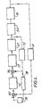
- Fig. 5 illustrates in diagrammatic form the speed control system as applied to the total inspection system. Brake pads 29, 30, 31 and 32 are forced into braking contact with the pipe wall by the high pressure hydraulic ram 34. The pressure applied by the ram 34 is controlled by the hydraulic control system 47 acting in conjunction with the vehicle speed transducer 11.
- the pipeline inspection system described in Fig.5 provides a vehicle moveable within the pipeline by a fluid flowing in the pipeline, the speed control for the vehicle including a braking system which imposes a continuous axial drag on the pipeline wall, and means for altering the pressure exerted between the brake pad and the wall within set limits and in relation to changes in the drag characteristic of the pipeline as measured by the change in the actual speed of the vehicle from a pre-determined desired speed thus varying the imposed axial drag between upper and lower limits such that the summation of the variable drag characteristic of the actual pipeline and the imposed drag remains approximately constant and the vehicle moves at a speed substantially equal to the average flow velocity of the fluid in the pipeline.
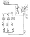
- FIG. 3 shows the hydraulic actuating system which comprises a number of wheel driven pumps 12, the wheels being driven as the on line inspection vehicle moves along the pipeline.
- Each high pressure pump pumps the oil through the non-return valves 52, 53 and 54 to a manifold which leads the high pressure oil to a combined relief and unloading valve 55 on to a non-return valve 56, the oil which passes through the non-return valve 56 is fed to high pressure accumulators 10.
- the oil from the non-return valve 56 also leads down the filter 60 which is used for filtering and cleaning the oil.
- the oil from the non-return valve 56 also leads down the filter 60 which is used for filtering and cleaning the oil.
- the oil from the filter 60 is fed into a servo-valve 63 which is used to control the brake pad braking rams 34 as shown in Figure 5 (only one is shown for ease of drawing).
- a return line leads the oil back through oil coolers 66, 67 and 68 which, for practical purposes, are concentric tubes in each of which a flow of pipeline gas is arranged to cool the hydraulic oil.
- a pressure transducer 72 is mounted within the oil line 73 which leads from the servo-valve 63 to the brake rams 34.
- the braking force is provided by the braking pads 29, 30, 31 and 32, these pads are hydraulically actuated to give the variable radial contact force against the internal surfaces of the pipe wall 28 and so vary the actual drag of the vehicle.
- the provision of low pressure accumulators in the hydraulic circuit have a two-fold operation firstly to act as a sump for hydraulic fluid and secondly to maintain the system's minimum operating pressure independent of the pipeline gas pressure.
- Disturbances to pipeline inclination, friction, and gas flow which occur during vehicle operation can act either to increase or to decrease the vehicle speed and therefore by virtue of the control system to increase or decrease the brake pressure provided to moderate the disturbance.
- the range of brake pressures available from the hydraulic system is limited by design considerations (such as stress levels, pump and seal performance etc). It is preferable therefore that in the absence of disturbances the brake pressure is held at a value somewhere near the middle of the range of available pressures. This will result in the system being able to compensate for changes in either direction.
- the braking control system operates as follows.
- the actual speed of the vehicle is measured by a wheel type velocity transducer.
- the signal from transducer 11 (as shown in Figures 1 and 5) is fed into a component (80) which can compare the signal with a pre-determined "speed reference signal” to produce a speed discrepancy signal.
- the discrepancy signal is fed into a two-term velocity controller 75 which determines the braking system pressure required to correct the speed discrepancy.
- the braking system pressure operates on the rams 34 and increases or decreases pressure between the brake pads and the pipe wall to maintain the actual brake pressure at the value required by the speed controller 75.
- the invention has many inherent advantages in providing a capability for controlling the speed of an inspection vehicle with accuracy within an acceptable speed range for example within a range of 4 ft/Sec to 12 ft/Sec, subject only to limitations introduced by the speed of fluid flow in the pipeline and to limit the maximum rate of change of speed to 1 ft/Sec. in 5 Sec.
Landscapes
- Physics & Mathematics (AREA)
- General Physics & Mathematics (AREA)
- Valves And Accessory Devices For Braking Systems (AREA)
- Regulating Braking Force (AREA)
- Investigating Or Analyzing Materials By The Use Of Ultrasonic Waves (AREA)
- Investigating Or Analyzing Materials By The Use Of Magnetic Means (AREA)
Applications Claiming Priority (2)
| Application Number | Priority Date | Filing Date | Title |
|---|---|---|---|
| GB3150777 | 1977-07-27 | ||
| GB3150777 | 1977-07-27 |
Publications (2)
| Publication Number | Publication Date |
|---|---|
| EP0001155A1 true EP0001155A1 (fr) | 1979-03-21 |
| EP0001155B1 EP0001155B1 (fr) | 1981-05-27 |
Family
ID=10324131
Family Applications (1)
| Application Number | Title | Priority Date | Filing Date |
|---|---|---|---|
| EP78300200A Expired EP0001155B1 (fr) | 1977-07-27 | 1978-07-26 | Système d'inspection de pipeline comprenant un vehicule muni de moyens de controle de sa vitesse, un tel vehicule comportant un dispositif sensible à la vitesse agissant sur des patins de frein |
Country Status (4)
| Country | Link |
|---|---|
| US (2) | US4458601A (fr) |
| EP (1) | EP0001155B1 (fr) |
| DE (1) | DE2860736D1 (fr) |
| NO (1) | NO146509C (fr) |
Cited By (2)
| Publication number | Priority date | Publication date | Assignee | Title |
|---|---|---|---|---|
| US7085414B2 (en) | 2004-05-05 | 2006-08-01 | Canon Kabushiki Kaisha | Characterization of display devices by averaging chromaticity values |
| CN114542992A (zh) * | 2022-02-24 | 2022-05-27 | 成都秦川物联网科技股份有限公司 | 基于物联网的天然气管网计量工况远程监控系统 |
Families Citing this family (15)
| Publication number | Priority date | Publication date | Assignee | Title |
|---|---|---|---|---|
| GB2097537B (en) * | 1981-04-27 | 1985-10-02 | British Gas Corp | A pipeline inspectioon vehicle |
| US5121694A (en) * | 1991-04-02 | 1992-06-16 | Zollinger William T | Pipe crawler with extendable legs |
| US5565633A (en) * | 1993-07-30 | 1996-10-15 | Wernicke; Timothy K. | Spiral tractor apparatus and method |
| US5454276A (en) * | 1993-07-30 | 1995-10-03 | Wernicke; Timothy K. | Multi-directional magnetic flux pipe inspection apparatus and method |
| EP0819480A1 (fr) * | 1996-07-18 | 1998-01-21 | Transglobal Ltd. | Appareil de nettoyage pour oléoducs ou gazoducs |
| DE29700298U1 (de) * | 1997-01-10 | 1998-05-07 | Scheiff GmbH, 53881 Euskirchen | Roboter zur Kanalsanierung |
| AU6768198A (en) * | 1997-03-24 | 1998-10-20 | Bj Services Company | Inspection with global positioning and inertial navigation |
| DE19724838A1 (de) * | 1997-06-12 | 1998-12-17 | Pipetronix Gmbh | Molch zur Lagebestimmung von Rohrleitungen |
| DE19746510C2 (de) * | 1997-10-22 | 2003-03-06 | Pii Pipetronix Gmbh | Vorrichtung zum Durchfahren von Rohrleitungen |
| US7543536B2 (en) * | 2006-10-31 | 2009-06-09 | The Boeing Company | Apparatus for transporting and positioning an inspection device within a walled cavity |
| US7685946B1 (en) * | 2007-06-25 | 2010-03-30 | Elstone Iii John M | Tubular transporter |
| EP2085155A1 (fr) * | 2008-01-31 | 2009-08-05 | HAPP Technology Ltd. | Procédé et appareil d'inspection de l'intégrité des parois d'un pipeline |
| US20100071487A1 (en) * | 2008-09-22 | 2010-03-25 | Revolution Mechanical Works, LLC | Self contained hydraulic system for a remote controlled unit |
| US8479345B2 (en) * | 2009-08-12 | 2013-07-09 | Tdw Delaware, Inc. | Speed control drive section with failsafe valve |
| US11446710B2 (en) * | 2018-12-14 | 2022-09-20 | The Boeing Company | Wash and dry tool for enclosed channels and method for use |
Citations (2)
| Publication number | Priority date | Publication date | Assignee | Title |
|---|---|---|---|---|
| US3495546A (en) * | 1967-11-03 | 1970-02-17 | American Mach & Foundry | Speed control device for pipeline inspection apparatus |
| US3561490A (en) * | 1969-03-03 | 1971-02-09 | Jewel E Little | Pipeline testing apparatus |
Family Cites Families (6)
| Publication number | Priority date | Publication date | Assignee | Title |
|---|---|---|---|---|
| US2127429A (en) * | 1937-03-01 | 1938-08-16 | Cincinnati Traction Building C | Braking |
| US2617499A (en) * | 1949-08-20 | 1952-11-11 | Jenkins | Inclined-railway safety car |
| US2651387A (en) * | 1951-01-10 | 1953-09-08 | Albert H Genter | Automatic safety brake |
| US3036530A (en) * | 1960-05-05 | 1962-05-29 | Harvest Queen Mill & Elevator | Governor for pipeline apparatus |
| US3243697A (en) * | 1961-07-03 | 1966-03-29 | Shell Oil Co | Self-contained pipeline inspecting system |
| US3758050A (en) * | 1969-11-25 | 1973-09-11 | R Watts | Photo inspection pod assembly for pipelines |
-
1978
- 1978-07-26 DE DE7878300200T patent/DE2860736D1/de not_active Expired
- 1978-07-26 EP EP78300200A patent/EP0001155B1/fr not_active Expired
- 1978-07-27 NO NO782586A patent/NO146509C/no unknown
-
1980
- 1980-08-29 US US06/182,658 patent/US4458601A/en not_active Expired - Lifetime
-
1981
- 1981-07-24 US US06/286,533 patent/US4388871A/en not_active Expired - Lifetime
Patent Citations (2)
| Publication number | Priority date | Publication date | Assignee | Title |
|---|---|---|---|---|
| US3495546A (en) * | 1967-11-03 | 1970-02-17 | American Mach & Foundry | Speed control device for pipeline inspection apparatus |
| US3561490A (en) * | 1969-03-03 | 1971-02-09 | Jewel E Little | Pipeline testing apparatus |
Cited By (2)
| Publication number | Priority date | Publication date | Assignee | Title |
|---|---|---|---|---|
| US7085414B2 (en) | 2004-05-05 | 2006-08-01 | Canon Kabushiki Kaisha | Characterization of display devices by averaging chromaticity values |
| CN114542992A (zh) * | 2022-02-24 | 2022-05-27 | 成都秦川物联网科技股份有限公司 | 基于物联网的天然气管网计量工况远程监控系统 |
Also Published As
| Publication number | Publication date |
|---|---|
| US4388871A (en) | 1983-06-21 |
| EP0001155B1 (fr) | 1981-05-27 |
| NO146509B (no) | 1982-07-05 |
| US4458601A (en) | 1984-07-10 |
| NO146509C (no) | 1982-10-13 |
| DE2860736D1 (en) | 1981-09-03 |
| NO782586L (no) | 1979-01-30 |
Similar Documents
| Publication | Publication Date | Title |
|---|---|---|
| EP0001155B1 (fr) | Système d'inspection de pipeline comprenant un vehicule muni de moyens de controle de sa vitesse, un tel vehicule comportant un dispositif sensible à la vitesse agissant sur des patins de frein | |
| US4170902A (en) | Pipeline inspection vehicles | |
| US4576097A (en) | Pipeline inspection vehicles | |
| US5864232A (en) | Magnetic flux pipe inspection apparatus for analyzing anomalies in a pipeline wall | |
| GB1508261A (en) | Accelerometer pig | |
| EP0018960A2 (fr) | Dispositif pour éliminer le risque de blocage des roues de véhicules pendant le freinage | |
| CA2209789A1 (fr) | Procede de mesure de debit par ultrasons | |
| US3937058A (en) | Method of determining the behaviour of a shock absorber in the sprung mass system of a vehicle and a jig for performing the method | |
| WO1997024585A1 (fr) | Systeme de mesure par ultrasons et mode de fonctionnement | |
| US4020674A (en) | Pipeline leak detector with baffles | |
| IE812450L (en) | Vertical roller mill. | |
| US4507971A (en) | Hydraulic filter for eliminating slow pressure fluctuations | |
| AU724203B2 (en) | Modified airflow algorithm with compensation for variations in main reservoir air pressure and ambient airflow | |
| CA1107061A (fr) | Systeme d'inspection de pipeline par vehicule a vitesse variable commandee par action sur les freins | |
| US4732045A (en) | Method for rapid acoustic emission testing of pressure vessels | |
| JPH01501220A (ja) | 液圧式自動車用ブレーキ装置内の圧力を連続的に監視する電気液圧式装置 | |
| US4612814A (en) | Flow meter and densitometer apparatus | |
| CA2261542C (fr) | Racleur pour la detection d'obstructions dans un pipeline | |
| RU2002114588A (ru) | Способ определения места течи жидкости или газа на участке трубопровода и устройство для его осуществления | |
| GB1576624A (en) | Leak detection | |
| JP2804600B2 (ja) | 流体管路系の圧力脈動制御装置 | |
| KATZ | Method and system for reducing drag on a body moving through a fluid medium(Patent) | |
| EP0815347B1 (fr) | Procede de mesure d'un debit et debitmetre | |
| CN109099028A (zh) | 一种摆缸马达压力检测系统 | |
| IT1097634B (it) | Veicolo per l'ispezione della superficie interna di condotte,particolarmente oleodotti e gasdotti |
Legal Events
| Date | Code | Title | Description |
|---|---|---|---|
| PUAI | Public reference made under article 153(3) epc to a published international application that has entered the european phase |
Free format text: ORIGINAL CODE: 0009012 |
|
| AK | Designated contracting states |
Designated state(s): DE FR GB NL |
|
| 17P | Request for examination filed | ||
| GRAA | (expected) grant |
Free format text: ORIGINAL CODE: 0009210 |
|
| AK | Designated contracting states |
Designated state(s): DE FR GB NL |
|
| REF | Corresponds to: |
Ref document number: 2860736 Country of ref document: DE Date of ref document: 19810903 |
|
| REG | Reference to a national code |
Ref country code: GB Ref legal event code: 732 |
|
| NLS | Nl: assignments of ep-patents |
Owner name: BRITISH GAS PLC TE LONDEN, GROOT-BRITTANNIE. |
|
| REG | Reference to a national code |
Ref country code: FR Ref legal event code: TP |
|
| PGFP | Annual fee paid to national office [announced via postgrant information from national office to epo] |
Ref country code: FR Payment date: 19930610 Year of fee payment: 16 |
|
| PGFP | Annual fee paid to national office [announced via postgrant information from national office to epo] |
Ref country code: GB Payment date: 19930615 Year of fee payment: 16 |
|
| PGFP | Annual fee paid to national office [announced via postgrant information from national office to epo] |
Ref country code: DE Payment date: 19930621 Year of fee payment: 16 |
|
| PGFP | Annual fee paid to national office [announced via postgrant information from national office to epo] |
Ref country code: NL Payment date: 19930731 Year of fee payment: 16 |
|
| PG25 | Lapsed in a contracting state [announced via postgrant information from national office to epo] |
Ref country code: GB Effective date: 19940726 |
|
| PG25 | Lapsed in a contracting state [announced via postgrant information from national office to epo] |
Ref country code: NL Effective date: 19950201 |
|
| NLV4 | Nl: lapsed or anulled due to non-payment of the annual fee | ||
| GBPC | Gb: european patent ceased through non-payment of renewal fee |
Effective date: 19940726 |
|
| PG25 | Lapsed in a contracting state [announced via postgrant information from national office to epo] |
Ref country code: FR Effective date: 19950331 |
|
| PG25 | Lapsed in a contracting state [announced via postgrant information from national office to epo] |
Ref country code: DE Effective date: 19950401 |
|
| REG | Reference to a national code |
Ref country code: FR Ref legal event code: ST |
|
| PLBE | No opposition filed within time limit |
Free format text: ORIGINAL CODE: 0009261 |
|
| STAA | Information on the status of an ep patent application or granted ep patent |
Free format text: STATUS: NO OPPOSITION FILED WITHIN TIME LIMIT |