EP0001172A1 - Vorrichtung und Verfahren zum Sortieren von heterogenen Festmaterialien - Google Patents
Vorrichtung und Verfahren zum Sortieren von heterogenen Festmaterialien Download PDFInfo
- Publication number
- EP0001172A1 EP0001172A1 EP78300343A EP78300343A EP0001172A1 EP 0001172 A1 EP0001172 A1 EP 0001172A1 EP 78300343 A EP78300343 A EP 78300343A EP 78300343 A EP78300343 A EP 78300343A EP 0001172 A1 EP0001172 A1 EP 0001172A1
- Authority
- EP
- European Patent Office
- Prior art keywords
- assembly
- rollers
- solids
- roller
- disc portions
- Prior art date
- Legal status (The legal status is an assumption and is not a legal conclusion. Google has not performed a legal analysis and makes no representation as to the accuracy of the status listed.)
- Withdrawn
Links
- 239000007787 solid Substances 0.000 title claims abstract description 47
- 238000000034 method Methods 0.000 title claims description 9
- 230000000712 assembly Effects 0.000 claims description 12
- 238000000429 assembly Methods 0.000 claims description 12
- 238000010276 construction Methods 0.000 claims description 6
- 238000011144 upstream manufacturing Methods 0.000 claims description 2
- 239000000463 material Substances 0.000 description 12
- 238000000926 separation method Methods 0.000 description 6
- 238000013019 agitation Methods 0.000 description 2
- 238000012986 modification Methods 0.000 description 1
- 230000004048 modification Effects 0.000 description 1
- 238000003466 welding Methods 0.000 description 1
Images
Classifications
-
- B—PERFORMING OPERATIONS; TRANSPORTING
- B07—SEPARATING SOLIDS FROM SOLIDS; SORTING
- B07B—SEPARATING SOLIDS FROM SOLIDS BY SIEVING, SCREENING, SIFTING OR BY USING GAS CURRENTS; SEPARATING BY OTHER DRY METHODS APPLICABLE TO BULK MATERIAL, e.g. LOOSE ARTICLES FIT TO BE HANDLED LIKE BULK MATERIAL
- B07B1/00—Sieving, screening, sifting, or sorting solid materials using networks, gratings, grids, or the like
- B07B1/12—Apparatus having only parallel elements
- B07B1/14—Roller screens
- B07B1/15—Roller screens using corrugated, grooved or ribbed rollers
Definitions
- This invention relates to an apparatus and method for classifying heterogeneous solids.
- a disc screen Such a screen is formed by a number of rollers rotating in the same direction about parallel axes disposed in a common horizontal plane. Each roller has a hub section on which radially extending discs are mounted, the location of the discs of one roller being staggered in relation to the discs on an adjacent roller and intermeshing with the discs on an adjacent roller to define apertures between adjacent discs and adjacent rollers. In operation the rollers are rotated in a common direction and refuse is fed onto the front end of the screen.
- Solids larger than the apertures formed between adjacent rollers are conveyed right across the screen owing to the rotation of the rollers while smaller solids fall through the apertures of the soreen and can thus be separated.
- smaller solids may rest on top of larger solids during their passage across the screen and are therefore not separated; this difficulty is particularly noticeable when the larger solids are of sheet-like form.
- an apparatus for classifying heterogeneous solids comprises a first assembly of rollers mounted for rotation about substantially parallel axes, each roller comprising a hub portion and a plurality of radially extending disc portions, the disc portions of each roller intermeshing with those of the or each adjacent roller and terminating adjacent the or each adjacent roller to define apertures therebetween, and drive means for rotating the rollers in a common direction, wherein a second assembly of rollers is provided having the features of the first assembly as defined above the arrangement being such that in use solids passing over the first assembly fall from the downstream end of the first assembly onto the upstream end of the second assembly.
- the space between the first and second assemblies through which in use the solids fall is preferably unobstructed so that the fall of the solids is a free fall.
- the fall should be of sufficient height to ensure that smaller solids supported on larger solids are most likely to be dislodged by the fall.
- the arrangement is such that, in use, the solids fall through a distance greater than the outer diameter of the disc portions of the rollers.
- the distance may be between 2 and 3 times this diameter.
- downstream edge of the last roller of the upper assembly is positioned directly above or. downstream of the centre of the first roller of the lower assembly. This ensures that solids falling onto the lower assembly are conveyed efficiently away from their landing point.. Excessive overlapping of the upper and lower assemblies wastes part of the length of the lower assembly.
- the outer edge of the disc portions may be circular or may be the shape of a regular polygon such as a hexagon.
- each of the roller assemblies may be substantially the same and the construction and spacing of each roller in an assembly may be substantially the same except for the location of the disc portions on adjacent rollers.
- the size of the apertures in one or both assemblies may be the same.
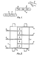
- the apperatus for class- ifying be terogeneous solids comprises a feed conveyer a haring a belt 2 and an end roller 3, a first roller assembly 4 and a second lower roller assembly 5.
- the upper roller assembly 4 comprises seven rollers 6 mounted for rotation about parallel axes each having a hub portion 7 and a plurality of disc portions 8 extending radially from the hub portion.
- the disc portions 8 which may be formed integrally or by welding annular disc members to the hub portion 7, terminate adjacent the adjacent roller or rollers and the location of the disc portions of one roller are staggered with respect to those of an-adjacent roller so that the disc portions of one roller intermesh with the disc portions of an adjacent roller to define apertures 9 between the rollers.
- Each of the rollers 6 is connected to a drive unit (not shown) which rotates all the rollers 6 in a common direction indicated by the arrow 10 in Figure 1 and at a common speed.
- the disc portions of the upper roller assembly 4 are shown in Figure 1 as having a circular outer edge.
- the lower roller assembly 5 is of the same construction as the roller assembly 4 with one exception, namely that the disc portions of the lower roller assembly 5 are shown in Figure 1 as having a hexagonal outer edge.
- the rollers of the lower roller assembly 5 are driven by the same drive unit as the rollers of the upper roller assembly 4 and in the same direction as indicated by the arrow 11 in Figure 1.
- the assemblies are positioned relative to one another such that the extreme downstream edge of the upper assembly 4 is vertically above the centre of the first roller of the lower assembly 5.
- the position of the last roller of the upper assembly with respect to the first roller of the lower assembly is important for ensuring good mechanical conveying. If substantial material falls behind the centre of the first roller it tends to accumulate in this position since there is little forward driving power in this region. For the same reason the feed conveyor should similarly overhang the first roller of the upper assembly.
- heterogeneous solids such as trade or domestic refuse is passed along the feed conveyor 1 and falls onto the right hand end of the upper roller assembly 4.
- the rotating rollers carry the refuse across the roller assembly to the left (as seen in Figure 1). During its passage across the roller assembly most of the materials smaller than the apertures 9 pass through the apertures while larger materials are carried over the top of the roller assembly 4. Some smaller and less dense materials will also be carried across the upper roller assembly 4 on top of larger materials particularly if sheet-like larger materials are present.
- Tests conducted using this apparatus produced a marked improvement in separation efficiency over a similar apparatus having fourteen rollers on a single level.
- This apparatus is suitable for performing initial separation of refuse.
- roller assemblies may be added below the lower assembly 4.
- shape of the disc portions may be changed and, in particular, the shape of the disc portions of the upper assembly may be the same as those of the lower assembly. If disc portions having a hexagonal outer edge are used, the rollers may be rotated at a slower rate than if disc portions having a circular outer edge are used since the hexagonal edge assists transfer of material across the rollers.
- roller assemblies described above it was found that rollers with circular disc portions when rotated at 85 r.p.m. produced similar results to the rollers with disc portions of hexagonal outline when rotated at 60 r.p.m. Other shapes such as oval, square or octagonal shapes may also be used for the disc portions.
- the disc portions may be knurled to assist transfer of material across the rollers.
- Disc portions with non-circular outer edges produce better agitation of the solids but suffer from the disadvantage that they may pinch materials between a disc portion and an adjacent roller as the spacing between the disc portion and the adjacent roller changes. Since in embodiments of the present invention refuse tumbles between the first and second roller assemblies the importance of agitation of the refuse during its passage over either assembly is greatly reduced and therefore disc portions having circular outer edges may be used.
- the rollers may be made by mounting annular rollers and discs alternately on a common shaft and clamping them together. This construction enables easy replacement of damaged discs and also allows the size of the apertures in the roller assembly to be varied.
- the height of the upper roller assembly above the lower roller assembly can be varied. It is considered that a height of between two and three times the diameter of the rollers is preferable since this gives an adequate distance for the solids to tumble but does not take up too much space. The distance must be sufficient to allow solids on top of sheet-like solids to fall off the sheet-like solids.
- each roller In the described embodiment only three disc portions are shown on each roller. In a commercial application where larger quantities of solids are to be separated the width of each roller would be increased and the number of disc portions on each roller correspondingly increased: for example six disc portions might be provided on each roller.
- the size of the apertures formed between adjacent discs and adjacent rollers may vary between one roller assembly and another or along one roller assembly. Also the speed of rotation of the rollers may increase with distance downstream of the feed-point.
- the solids being classified need not pass directly from the end of the upper assembly onto the lower assembly, they may alternatively pass from the upper assembly onto a conveyor belt and then onto the lower assembly, the dropping of the solids occuring between the conveyor belt and one of the lower or upper assemblies.
Landscapes
- Combined Means For Separation Of Solids (AREA)
Applications Claiming Priority (2)
| Application Number | Priority Date | Filing Date | Title |
|---|---|---|---|
| GB3692277 | 1977-09-05 | ||
| GB3692277 | 1977-09-05 |
Publications (1)
| Publication Number | Publication Date |
|---|---|
| EP0001172A1 true EP0001172A1 (de) | 1979-03-21 |
Family
ID=10392267
Family Applications (1)
| Application Number | Title | Priority Date | Filing Date |
|---|---|---|---|
| EP78300343A Withdrawn EP0001172A1 (de) | 1977-09-05 | 1978-09-04 | Vorrichtung und Verfahren zum Sortieren von heterogenen Festmaterialien |
Country Status (2)
| Country | Link |
|---|---|
| EP (1) | EP0001172A1 (de) |
| JP (1) | JPS5490658A (de) |
Cited By (5)
| Publication number | Priority date | Publication date | Assignee | Title |
|---|---|---|---|---|
| EP0093220A1 (de) * | 1982-05-04 | 1983-11-09 | Beloit Corporation | Verfahren und Vorrichtung zur Wiedergewinnung von Brennstoff und anderen Mitteln aus Müll durch Verwendung von Scheibenrosten |
| EP0136442A1 (de) * | 1983-08-05 | 1985-04-10 | Speno International S.A. | Sieb für Eisenbahnschotter, das die Eliminierung von Erd-Teilen und von Schotter geringerer als vorgegebener Grösse erlaubt |
| DE4408903A1 (de) * | 1994-03-16 | 1995-09-21 | Ernst Josef Kronenberger | Sieb zur Aufbereitung bindiger Aushubmassen für den Wiedereinbau |
| WO1998020986A1 (en) * | 1996-11-13 | 1998-05-22 | British Technology Group Intercorporate Licensing Limited | Solids separator |
| DE19903249A1 (de) * | 1999-01-28 | 2000-08-03 | Krupp Foerdertechnik Gmbh | Scheibenrost |
Families Citing this family (2)
| Publication number | Priority date | Publication date | Assignee | Title |
|---|---|---|---|---|
| JPH059103Y2 (de) * | 1986-04-11 | 1993-03-05 | ||
| JP2675269B2 (ja) * | 1994-11-28 | 1997-11-12 | 株式会社御池鐵工所 | 選別機 |
Citations (4)
| Publication number | Priority date | Publication date | Assignee | Title |
|---|---|---|---|---|
| GB448838A (en) * | 1935-03-18 | 1936-06-16 | Krupp Fried Grusonwerk Ag | An improved disc roller classifying grate for coal |
| GB518330A (en) * | 1938-09-08 | 1940-02-23 | Carves Simon Ltd | Improvements in rotary grizzly screens |
| GB1087921A (en) * | 1963-09-11 | 1967-10-18 | Kenneth Martin Allen | A sorting machine |
| GB1177769A (en) * | 1965-12-24 | 1970-01-14 | Rudolf Zemanek | A Wood Chip Separating Apparatus |
-
1978
- 1978-09-04 EP EP78300343A patent/EP0001172A1/de not_active Withdrawn
- 1978-09-04 JP JP10845178A patent/JPS5490658A/ja active Pending
Patent Citations (4)
| Publication number | Priority date | Publication date | Assignee | Title |
|---|---|---|---|---|
| GB448838A (en) * | 1935-03-18 | 1936-06-16 | Krupp Fried Grusonwerk Ag | An improved disc roller classifying grate for coal |
| GB518330A (en) * | 1938-09-08 | 1940-02-23 | Carves Simon Ltd | Improvements in rotary grizzly screens |
| GB1087921A (en) * | 1963-09-11 | 1967-10-18 | Kenneth Martin Allen | A sorting machine |
| GB1177769A (en) * | 1965-12-24 | 1970-01-14 | Rudolf Zemanek | A Wood Chip Separating Apparatus |
Cited By (5)
| Publication number | Priority date | Publication date | Assignee | Title |
|---|---|---|---|---|
| EP0093220A1 (de) * | 1982-05-04 | 1983-11-09 | Beloit Corporation | Verfahren und Vorrichtung zur Wiedergewinnung von Brennstoff und anderen Mitteln aus Müll durch Verwendung von Scheibenrosten |
| EP0136442A1 (de) * | 1983-08-05 | 1985-04-10 | Speno International S.A. | Sieb für Eisenbahnschotter, das die Eliminierung von Erd-Teilen und von Schotter geringerer als vorgegebener Grösse erlaubt |
| DE4408903A1 (de) * | 1994-03-16 | 1995-09-21 | Ernst Josef Kronenberger | Sieb zur Aufbereitung bindiger Aushubmassen für den Wiedereinbau |
| WO1998020986A1 (en) * | 1996-11-13 | 1998-05-22 | British Technology Group Intercorporate Licensing Limited | Solids separator |
| DE19903249A1 (de) * | 1999-01-28 | 2000-08-03 | Krupp Foerdertechnik Gmbh | Scheibenrost |
Also Published As
| Publication number | Publication date |
|---|---|
| JPS5490658A (en) | 1979-07-18 |
Similar Documents
| Publication | Publication Date | Title |
|---|---|---|
| US5109988A (en) | Machine and method for sorting out fines, pins, and over-thick wood chips | |
| DE69421128T2 (de) | Siebmaschine | |
| US5348162A (en) | Machine for processing goods, especially refuse, for sorting it | |
| CN110732486B (zh) | 一种贝壳筛选装置 | |
| US4903845A (en) | Machine and method for separating fines from wood chips | |
| US2997086A (en) | Beet screening and cleaning device | |
| EP3500376B1 (de) | Selbstreinigendes rollensieb | |
| US4871073A (en) | Disc screen separator device | |
| CN113320917B (zh) | 一种速冻丸子筛选输送设备 | |
| CA1116125A (en) | Rotating disc apparatus for selective sorting of material chips | |
| CN110090798A (zh) | 一种餐厨垃圾物料分选机 | |
| US20200338595A1 (en) | Auger disc for use in disc screen | |
| US3963032A (en) | Threshing machine | |
| GB2045113A (en) | Rotary screen for refuse sizing | |
| CN217528285U (zh) | 一种分拣装置 | |
| CN215905283U (zh) | 一种坚果类物料均匀输送装置 | |
| US3080860A (en) | Brick cleaning machine | |
| SU1542633A1 (ru) | Сепарирующее устройство | |
| CN211322876U (zh) | 茶叶自动拼配除渣设备 | |
| CN109225916B (zh) | 一种枣子送料机构 | |
| CN209753338U (zh) | 连续滚动式核桃分选装置 | |
| CN217616129U (zh) | 一种红枣筛选机用自动进料装置 | |
| US2145330A (en) | Threshing apparatus | |
| US3667599A (en) | Continuous corrugated belt with wire screen | |
| CN223996576U (zh) | 一种用于秸秆杂质分离的风选机 |
Legal Events
| Date | Code | Title | Description |
|---|---|---|---|
| PUAI | Public reference made under article 153(3) epc to a published international application that has entered the european phase |
Free format text: ORIGINAL CODE: 0009012 |
|
| AK | Designated contracting states |
Designated state(s): BE DE FR NL SE |
|
| STAA | Information on the status of an ep patent application or granted ep patent |
Free format text: STATUS: THE APPLICATION IS DEEMED TO BE WITHDRAWN |
|
| 18D | Application deemed to be withdrawn | ||
| RIN1 | Information on inventor provided before grant (corrected) |
Inventor name: SMITH, CLIVE RICHARD |