EP0001188A1 - Dispositif sensible à la pression et système de contrôle ou de régulation comprenant ce dispositif - Google Patents
Dispositif sensible à la pression et système de contrôle ou de régulation comprenant ce dispositif Download PDFInfo
- Publication number
- EP0001188A1 EP0001188A1 EP78300379A EP78300379A EP0001188A1 EP 0001188 A1 EP0001188 A1 EP 0001188A1 EP 78300379 A EP78300379 A EP 78300379A EP 78300379 A EP78300379 A EP 78300379A EP 0001188 A1 EP0001188 A1 EP 0001188A1
- Authority
- EP
- European Patent Office
- Prior art keywords
- pressure
- diaphragm
- chamber
- diaphragms
- fluid
- Prior art date
- Legal status (The legal status is an assumption and is not a legal conclusion. Google has not performed a legal analysis and makes no representation as to the accuracy of the status listed.)
- Granted
Links
- 230000001105 regulatory effect Effects 0.000 title claims abstract description 7
- 239000012530 fluid Substances 0.000 claims abstract description 28
- 239000007788 liquid Substances 0.000 claims abstract description 28
- 230000007246 mechanism Effects 0.000 claims description 5
- 238000000034 method Methods 0.000 claims description 5
- 230000008569 process Effects 0.000 claims description 5
- 241000239290 Araneae Species 0.000 claims description 3
- 230000001276 controlling effect Effects 0.000 claims description 3
- 230000004044 response Effects 0.000 claims description 2
- 239000011324 bead Substances 0.000 claims 1
- 230000002411 adverse Effects 0.000 abstract description 6
- 239000007789 gas Substances 0.000 description 13
- 230000006378 damage Effects 0.000 description 3
- 230000007423 decrease Effects 0.000 description 3
- 239000000463 material Substances 0.000 description 3
- IJGRMHOSHXDMSA-UHFFFAOYSA-N Atomic nitrogen Chemical compound N#N IJGRMHOSHXDMSA-UHFFFAOYSA-N 0.000 description 2
- 238000012544 monitoring process Methods 0.000 description 2
- 238000003466 welding Methods 0.000 description 2
- 239000004677 Nylon Substances 0.000 description 1
- 230000009471 action Effects 0.000 description 1
- 230000004075 alteration Effects 0.000 description 1
- 235000013405 beer Nutrition 0.000 description 1
- 230000008901 benefit Effects 0.000 description 1
- 230000000740 bleeding effect Effects 0.000 description 1
- 239000002775 capsule Substances 0.000 description 1
- 238000004140 cleaning Methods 0.000 description 1
- 230000008602 contraction Effects 0.000 description 1
- 238000013016 damping Methods 0.000 description 1
- 230000007547 defect Effects 0.000 description 1
- 230000000694 effects Effects 0.000 description 1
- 231100001261 hazardous Toxicity 0.000 description 1
- 238000003780 insertion Methods 0.000 description 1
- 230000037431 insertion Effects 0.000 description 1
- 238000004519 manufacturing process Methods 0.000 description 1
- 238000005259 measurement Methods 0.000 description 1
- 229910052757 nitrogen Inorganic materials 0.000 description 1
- 229920001778 nylon Polymers 0.000 description 1
- -1 polytetrafluoroethylene Polymers 0.000 description 1
- 229920001343 polytetrafluoroethylene Polymers 0.000 description 1
- 239000004810 polytetrafluoroethylene Substances 0.000 description 1
- 230000008439 repair process Effects 0.000 description 1
- 239000012858 resilient material Substances 0.000 description 1
- 238000007789 sealing Methods 0.000 description 1
- 238000000926 separation method Methods 0.000 description 1
- 229910001220 stainless steel Inorganic materials 0.000 description 1
- 239000010935 stainless steel Substances 0.000 description 1
- 238000003860 storage Methods 0.000 description 1
- 239000000126 substance Substances 0.000 description 1
- 231100000331 toxic Toxicity 0.000 description 1
- 230000002588 toxic effect Effects 0.000 description 1
Images
Classifications
-
- G—PHYSICS
- G01—MEASURING; TESTING
- G01L—MEASURING FORCE, STRESS, TORQUE, WORK, MECHANICAL POWER, MECHANICAL EFFICIENCY, OR FLUID PRESSURE
- G01L11/00—Measuring steady or quasi-steady pressure of a fluid or a fluent solid material by means not provided for in group G01L7/00 or G01L9/00
- G01L11/004—Measuring steady or quasi-steady pressure of a fluid or a fluent solid material by means not provided for in group G01L7/00 or G01L9/00 by the use of counterbalancing forces
- G01L11/006—Measuring steady or quasi-steady pressure of a fluid or a fluent solid material by means not provided for in group G01L7/00 or G01L9/00 by the use of counterbalancing forces hydraulic or pneumatic counterbalancing forces
-
- G—PHYSICS
- G05—CONTROLLING; REGULATING
- G05D—SYSTEMS FOR CONTROLLING OR REGULATING NON-ELECTRIC VARIABLES
- G05D9/00—Level control, e.g. controlling quantity of material stored in vessel
- G05D9/04—Level control, e.g. controlling quantity of material stored in vessel with auxiliary non-electric power
Definitions
- This invention relates to a pr ⁇ sure transmitting device which is useful as a functional element of a control or regulating system.
- a pressure transmitting device which can be used to give a pneumatic or hydraulic signal which can be converted to an electrical signal which can be fed to a transducer and thereby serve to control a process in which, for example, the level of a liquid has to be constantly monitored or measured.
- the device is invariably required in order to be able to supervise or control an industrial process, such as the brewing of beer, where the level of liquid in brewing and storage vats has to be monitored.
- the pressure transmitting device of British Patent No. 1,270,391 comprises a chamber, a diaphragm closing one end of the chamber, a valve member fixed to the diaphragm, a bleed nozzle mounted in the chamber so as to be closable by the valve member upon movement of the diaphragm and means for admitting a fluid under pressure into the chamber.
- the arrangement is such that, when the pressure on the outside of the diaphragm remote from the chamber is greater than the pressure in the chamber, the valve member closes the nozzle to allow the pressure in the chamber to build up, by admission of said fluid, to a value where the pressure in the chamber is the same as that on the outside of the diaphragam, thereby opening the nozzle and allowing the fluid to bleed away from the chamber through the nozzle.
- a damper mechanism may be carried by the valve member and engages against the wall or walls of the chamber for the purpose of suppressing pneumatic or hydraulic harmonica of the diaphragm, but it has been found that the damper mechanism may be dispensed with in certain cases.
- the device is preferably substantially mushroom-shaped, having a head mounting and supporting said diaphragm and a stem defining said chamber.
- the aforesaid pressure transmitting device is a functional element of a control system and may be fitted in pipes or tanks which form part or are controlled by the control system.
- the pipes or tanks may be subjected to pressures which are adverse to the transmitting device, such adverse pressures including ram pressures or vacuum pressures which may distort the diaphragm of the transmitting device to such an extent that its control characteristics are destroyed, or even in rare circumstances to such an extent that the diaphram is ruptured with possible subsequent loss of pressure or valuable fluids.
- a pressure transmitting device useful as a functional element of a control or regulating system, comprising a stem defining a chamber, a first diaphragm closing one end of the chamber, a second diaphragm, a separating member attached to and separating the first and second diaphragms, a head member mounting and supporting the first and second diaphragms, a valve member associated with the first diaphragm, a bleed nozzle mounted in the chamber so as to be closeable by the valve member upon movement of the first diaphragm and means for admitting a fluid under pressure into the chamber, the first and second diaphragms and the head member defining a space which is intended to be occupied by a gas or liquid fill and sealed, the arrangement of the device being such that when the pressure on the outside of the second diaphragm remote from the chamber is greater than the pressure in the chamber, the second diaphragm moves to increase the pressure in the gas or liquid fill, and the first di
- the two diaphragms including the separating member and the head member may be made in the form of a capsule which can be attached to a secondary head member connected to the stem.
- the device of the present invention may incorporate a damper mechanism if it is desired to suppress pneumatic or hydraulic harmonics of the diaphragm, but it may be dispensed with, especially in cases where such harmonics can be tolerated or the device is not subjected to such rapid pressure changes as to be likely to cause hunting of the diaphragm, e.g. where steady state pressure readings rather than instantaneous pressure charge readings are required.
- a damping mechanism may take the form of a spider member the body of which is attached to the valve member made and the legs of which are in frictional contact with the walls of the chamber.
- the spider member is preferably made from a resilient material which has a low coefficient of friction when in contact with the material of the walls of the chamber in the presence of the fluid, such as polytetrafluoroethylene or a chlorinated derivative thereof, or nylon.
- the gas or liquid fill is preferably a gas or liquid which is compatible with the process being monitored, and which will not create any undue hazard if leakage due to diaphragm rupture or damage occurs. It the fill is a gas, nitrogen is preferred to air as it has better characteristics under changing temperature than has air for the purposes of the present invention.
- the fluid admitted to the chamber may be air, or any convenient gas or liquid for example an oil, but if air is not used it is preferable to provide a recirculation system for the fluid connected to the nozzle and to the means for.-admitting the fluid, and preferably comprising a fluid reservoir.
- a control or regulating system comprising at least one pressure transmitting device as indicated above mounted in a tank, pipe or the like in which or through which the level or flow of a liquid is to be controlled, so that said second diaphragm is in contact with the liquid, means for supplying a fluid under pressure into said chamber, signal-generating means responsive to the pressure of fluid in said chamber, and control means for controlling the level and/or flow of the liquid in response to signals generated by said signal-generating means.
- the device may be used for monitoring the pressure inside closed tanks, or coupled with another such device, for monitoring the depth of liquid in a pressurised tank.
- the device may be mounted in a tank or pipe by bolting a flange over the head or threading the outside of the stem for a nut, or in other fashion.
- the device according to the present invention is advantageously employed in situations where there are large temperature variations.
- the separating member between the diaphragms substantially prevents distortion and variations in the distance of separation between the diaphragms due to expansion and contraction of the gas or liquid fill. It is preferable if the diaphragms, the separating member, and the valve member are co-axially aligned. In the absence of the separating member, expansion of the gas or liquid fill due to a temperature rise would cause the diaphragms to move apart, the first diaphragm moving towards the nozzle, thus upsetting the calibration of the device.
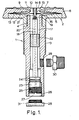
- a pressure transmitter which is substantially mushroom-shaped having a stem 1 and a cap 2.
- the stem consists of an open-ended tube of substantially circular cross-section having an externally threaded portion 3 whereby the transmitter can be fitted to the apparatus with which it is to be used.
- One end 4 of the stem is formed with reduced external diameter and is externally threaded to receive the cap 2.
- the cap 2 consists of a head member 5 in the form of a flanged spigot having an internally threaded stem to engage the end 4 of the stem 1, and an inverted cup-like head member 6 formed with a central aperature and engaging over the head member 5.
- the member 5 mounts a first diaphragm 7 and the member 6 mounts a second diaphragm 8.
- Each diaphragm is conveniently made of stainless steel and is preferably welded to the outer edge of its respective head member by argon-arc welding.
- the side wall of head member 5 engages the inside wall of the head member 6 in a pressure-tight and fluid-tight manner as by screw threading and it will be seen that the central portion of the head member 6 is effectively captive between the two diaphragms 7 and 8.
- the diaphragms 7 and 8 have corrugations 9 and 10 respectively which can mate with matching corrugations 11 and 12 respectively in the head member 6, and, in addition, the head member 5 is formed with corrugations 13 matching those on the diaphragm 7.
- the corrugations may be annular (as shown), or resemble cartwheel or spoke layouts, or have an other desired configuration.
- the diaphragms 7 and 8 are separated by a separating member comprising a pallet 14, welded to diaphragm 8 and passing through the central aperture in the head member 6.
- the pallet 14 is attached to diaphragm 7 by a plug 15, which passes through the diaphragm 7 and which forms a valve member.
- the space defined between the diaphragms 7 and 8 and the head members 5 and 6 and surroundiug the pallet 14, is filled with a gas or liquid fill before insertion of the plug 15 which is provided with a seal 19.
- the stem 1 of the transmitter is hollow to define a substantially cylindrical chamber 17.
- a nozzle 18 is positioned within the stem 1 within its axis of the stem 1.
- the nozzle has a bleed orifice 19 which leads into a bore 20 extending through the length of the nozzle.
- the nozzle has an accurately flat end face 21 for engaging against the end face of the plug 15.
- the nozzle is guided in the chamber 17 by a centring block 22 which is in the form of a cylinder with four flats formed on its side.
- the nozzle has a widened portion 23 which carries two 0-rings 24 for sealing the lower end of the nozzle, and which is mounted on a threaded portion 25 which engages internal threading 26 formed on the interior of the stem 1, the threaded portion 25 being formed with a groove 27 so that the longitudinal position of the nozzle in the stem can be adjusted by means of a screw-driver.
- the lower end of the stem 1 is closed by a vent cap 28 formed with a: bore registering with the bore 20, and with a cruciform recess 31.
- the stem is formed with a threaded aperture 29 in which a' connector 30 can be fixed for admitting pressure fluid to the interior of the stem.
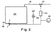
- the transmitter is, for example, fitted in the wall of a tank 40 in the manner shown in Figure 2 so that the contents of the tank exert on the diaphragm 8 a pressure which it is desired to control so as to control the level in the tank 40.
- the tank 40 has an inlet pipe 41 for liquid and an outlet pipe 42 with the pressure transmitter 1, 2; fitted in the bottom of the tank.
- pressure fluid for example air
- a pressure regulator 45 which is arranged to feed air to the chamber at a substantially constant flow rate at which it can be exhausted through the bleed orifice 19.
- a convenient rate of flow for the air is Ii cu. ft. per hour.
- the pressure exerted on the outside of the diaphragm 8 is the same as the pressure in the chamber 17, the end face 15 of the set-screw 14 and the end face 21 of the nozzle will be disengaged and the air will bleed through the orifice 19, the bore 20 and the vent cap 28 to atmosphere.
- both diaphragms will move downwardly (as viewed in Fig 1.) and the plug 15 will seal off the - bleed orifice 19 in the end of the nozzle thereby preventing air in the chamber from bleeding to atmosphere.
- the pressure of the air admitted through the connector 30 now increases until it is substantially the same as the pressure on the outer surface of the diaphragm whereupon the diaphragm lifts the set-screw off the nozzle end and air again bleeds to atmosphere.
- the increase in the pressure-of the air admitted to the stem can readily be measured, if desired, on an indicator 46 thereby providing a measure of the increase in pressure applied to the outer surface of the diaphragm.
- the fluid being admitted to the chamber is air, and the tank is operating below atmospheric pressure, it may be necessary to apply vacuum to the nozzle 18 to achieve the required pressure balance.
- the diaphragm 7 is supported by the head member 6, and the diaphragm 8 is partially supported by the gas or liquid fill and the pallet 14, whereas under high pressure overload conditions, the diaphragms 7 and 8 are supported by the head members 5 and 6 respectively, and also by the pallet 14.
- liquid or gas fill between the diaphragms will cushion the diaphragms against any adverse pressures such as mentioned above so that there is less risk of distortion of the diaphragms.
- an important advantage of the present transmitter is that if by any chance one or other of the diaphragms should rupture, either due to the effect of any adverse pressure or due to any welding defect in attaching the diaphragms, the operating characteristic of the transmitter will alter fundamentally as the remaining diaphragm is subjected to the operating pressure. This alteration of the operating characteristic will provide a signal for the control means which can be used to operate an alarm or shut down the process being controlled, either in total or in part until a repair can be effected. Furthermore, since one diaphagm still remains, the tank is sealed so that its content cannot leak through the transmitter which may be of substantial importance where the transmitter is used in the control of process involving, toxic, hazardous or valuable chemicals.
Landscapes
- Physics & Mathematics (AREA)
- General Physics & Mathematics (AREA)
- Engineering & Computer Science (AREA)
- Power Engineering (AREA)
- Automation & Control Theory (AREA)
- Control Of Fluid Pressure (AREA)
Applications Claiming Priority (2)
| Application Number | Priority Date | Filing Date | Title |
|---|---|---|---|
| GB3798477 | 1977-09-12 | ||
| GB3798477 | 1977-09-12 |
Publications (2)
| Publication Number | Publication Date |
|---|---|
| EP0001188A1 true EP0001188A1 (fr) | 1979-03-21 |
| EP0001188B1 EP0001188B1 (fr) | 1983-04-27 |
Family
ID=10400399
Family Applications (1)
| Application Number | Title | Priority Date | Filing Date |
|---|---|---|---|
| EP19780300379 Expired EP0001188B1 (fr) | 1977-09-12 | 1978-09-12 | Dispositif sensible à la pression et système de contrôle ou de régulation comprenant ce dispositif |
Country Status (2)
| Country | Link |
|---|---|
| EP (1) | EP0001188B1 (fr) |
| DE (1) | DE2862238D1 (fr) |
Cited By (5)
| Publication number | Priority date | Publication date | Assignee | Title |
|---|---|---|---|---|
| WO1987004789A1 (fr) * | 1986-02-07 | 1987-08-13 | Seetru Limited | Protection contre les surcharges de detecteurs de pression pneumatique pourvus d'une seule membrane |
| BE1008508A3 (nl) * | 1994-07-19 | 1996-05-07 | Bogerd Navtec Naamloze Vennoot | Scheidingsmembraan. |
| WO2003025534A1 (fr) * | 2001-09-07 | 2003-03-27 | Endress + Hauser Gmbh + Co. Kg | Appareil de mesure de pression |
| JP2022176769A (ja) * | 2021-05-17 | 2022-11-30 | 日本空圧システム株式会社 | 圧力検出装置 |
| CN116147822A (zh) * | 2021-11-23 | 2023-05-23 | 精量电子(深圳)有限公司 | 压力传感器 |
Families Citing this family (1)
| Publication number | Priority date | Publication date | Assignee | Title |
|---|---|---|---|---|
| JP4708679B2 (ja) * | 2003-03-28 | 2011-06-22 | 株式会社デンソー | 液封型圧力センサ |
Citations (8)
| Publication number | Priority date | Publication date | Assignee | Title |
|---|---|---|---|---|
| US2649714A (en) * | 1951-12-20 | 1953-08-25 | Du Pont | Liquid level gauge |
| GB815744A (en) * | 1954-09-21 | 1959-07-01 | Gen Electric | Improvements relating to pressure transmitters for liquid metal systems |
| GB1172400A (en) * | 1967-07-25 | 1969-11-26 | Revue Thommen Ag | A Pressure Gauge Protection Device |
| GB1270391A (en) * | 1968-01-22 | 1972-04-12 | Holledge Instr Ltd | Pressure transmitter |
| GB1287449A (en) * | 1969-07-23 | 1972-08-31 | Westinghouse Brake & Signal | Material sensing device |
| GB1327754A (en) * | 1969-11-28 | 1973-08-22 | Drayron Conttrols Ltd | Apparatus for measuring liquid levels |
| US3845664A (en) * | 1972-12-26 | 1974-11-05 | J Perry | Pressure transducer |
| GB1414642A (en) * | 1972-07-13 | 1975-11-19 | Wf Controls Ltd | Pressure transmitting device |
-
1978
- 1978-09-12 DE DE7878300379T patent/DE2862238D1/de not_active Expired
- 1978-09-12 EP EP19780300379 patent/EP0001188B1/fr not_active Expired
Patent Citations (8)
| Publication number | Priority date | Publication date | Assignee | Title |
|---|---|---|---|---|
| US2649714A (en) * | 1951-12-20 | 1953-08-25 | Du Pont | Liquid level gauge |
| GB815744A (en) * | 1954-09-21 | 1959-07-01 | Gen Electric | Improvements relating to pressure transmitters for liquid metal systems |
| GB1172400A (en) * | 1967-07-25 | 1969-11-26 | Revue Thommen Ag | A Pressure Gauge Protection Device |
| GB1270391A (en) * | 1968-01-22 | 1972-04-12 | Holledge Instr Ltd | Pressure transmitter |
| GB1287449A (en) * | 1969-07-23 | 1972-08-31 | Westinghouse Brake & Signal | Material sensing device |
| GB1327754A (en) * | 1969-11-28 | 1973-08-22 | Drayron Conttrols Ltd | Apparatus for measuring liquid levels |
| GB1414642A (en) * | 1972-07-13 | 1975-11-19 | Wf Controls Ltd | Pressure transmitting device |
| US3845664A (en) * | 1972-12-26 | 1974-11-05 | J Perry | Pressure transducer |
Cited By (5)
| Publication number | Priority date | Publication date | Assignee | Title |
|---|---|---|---|---|
| WO1987004789A1 (fr) * | 1986-02-07 | 1987-08-13 | Seetru Limited | Protection contre les surcharges de detecteurs de pression pneumatique pourvus d'une seule membrane |
| BE1008508A3 (nl) * | 1994-07-19 | 1996-05-07 | Bogerd Navtec Naamloze Vennoot | Scheidingsmembraan. |
| WO2003025534A1 (fr) * | 2001-09-07 | 2003-03-27 | Endress + Hauser Gmbh + Co. Kg | Appareil de mesure de pression |
| JP2022176769A (ja) * | 2021-05-17 | 2022-11-30 | 日本空圧システム株式会社 | 圧力検出装置 |
| CN116147822A (zh) * | 2021-11-23 | 2023-05-23 | 精量电子(深圳)有限公司 | 压力传感器 |
Also Published As
| Publication number | Publication date |
|---|---|
| EP0001188B1 (fr) | 1983-04-27 |
| DE2862238D1 (en) | 1983-06-01 |
Similar Documents
| Publication | Publication Date | Title |
|---|---|---|
| US3161051A (en) | Level indicating device and system | |
| US2902861A (en) | Pressure sensing device | |
| US4043355A (en) | Combined flow measuring and valve leakage indicator | |
| US2841984A (en) | Connection for fluid pressure operated devices | |
| US20160349128A1 (en) | Diaphragm pressure gauge with monitoring function | |
| US3845664A (en) | Pressure transducer | |
| US4708014A (en) | Device for testing of containers as to leakage or defects | |
| US4012945A (en) | Means for testing containers for leakage | |
| EP0001188B1 (fr) | Dispositif sensible à la pression et système de contrôle ou de régulation comprenant ce dispositif | |
| US4157656A (en) | Leak detection system | |
| US2725749A (en) | Pressure gage protector | |
| US4107982A (en) | Vessel for atmosphere for use with material testing device | |
| US2619107A (en) | Fluid flow control system | |
| US2418614A (en) | Liquid level gauge | |
| US4128013A (en) | Pressure transducer | |
| US3085422A (en) | Hydro-dynamic loader | |
| US2704552A (en) | Fluid flow control valves | |
| US4063057A (en) | Temperature compensated pressure differential sensing devices, including improved press-to-test and glass header switch mounting | |
| US4112760A (en) | Liquid level measuring device | |
| GB2148397A (en) | Double enclosure pressure vessel | |
| US3922515A (en) | Temperature compensated pressure differential sensing device with switch actuated by pressure capsule | |
| CN112577667B (zh) | 一种毛细管压力变送器的快速校验装置及方法 | |
| US3451420A (en) | Liquid level transmitter | |
| US4454760A (en) | Pressure sensing system | |
| US3491599A (en) | Pressure transmitter |
Legal Events
| Date | Code | Title | Description |
|---|---|---|---|
| PUAI | Public reference made under article 153(3) epc to a published international application that has entered the european phase |
Free format text: ORIGINAL CODE: 0009012 |
|
| AK | Designated contracting states |
Designated state(s): BE CH DE FR GB NL SE |
|
| 17P | Request for examination filed | ||
| GRAA | (expected) grant |
Free format text: ORIGINAL CODE: 0009210 |
|
| AK | Designated contracting states |
Designated state(s): BE CH DE FR GB NL SE |
|
| REF | Corresponds to: |
Ref document number: 2862238 Country of ref document: DE Date of ref document: 19830601 |
|
| ET | Fr: translation filed | ||
| PGFP | Annual fee paid to national office [announced via postgrant information from national office to epo] |
Ref country code: GB Payment date: 19900831 Year of fee payment: 13 |
|
| PGFP | Annual fee paid to national office [announced via postgrant information from national office to epo] |
Ref country code: FR Payment date: 19900919 Year of fee payment: 13 |
|
| PGFP | Annual fee paid to national office [announced via postgrant information from national office to epo] |
Ref country code: SE Payment date: 19900921 Year of fee payment: 13 |
|
| PGFP | Annual fee paid to national office [announced via postgrant information from national office to epo] |
Ref country code: CH Payment date: 19900925 Year of fee payment: 13 |
|
| PGFP | Annual fee paid to national office [announced via postgrant information from national office to epo] |
Ref country code: NL Payment date: 19900930 Year of fee payment: 13 |
|
| PGFP | Annual fee paid to national office [announced via postgrant information from national office to epo] |
Ref country code: BE Payment date: 19901005 Year of fee payment: 13 |
|
| PGFP | Annual fee paid to national office [announced via postgrant information from national office to epo] |
Ref country code: DE Payment date: 19901031 Year of fee payment: 13 |
|
| PG25 | Lapsed in a contracting state [announced via postgrant information from national office to epo] |
Ref country code: GB Effective date: 19910912 |
|
| PG25 | Lapsed in a contracting state [announced via postgrant information from national office to epo] |
Ref country code: SE Effective date: 19910913 |
|
| PG25 | Lapsed in a contracting state [announced via postgrant information from national office to epo] |
Ref country code: CH Effective date: 19910930 Ref country code: BE Effective date: 19910930 |
|
| BERE | Be: lapsed |
Owner name: HOLLEDGE (INSTRUMENTS) LTD Effective date: 19910930 |
|
| PG25 | Lapsed in a contracting state [announced via postgrant information from national office to epo] |
Ref country code: NL Effective date: 19920401 |
|
| GBPC | Gb: european patent ceased through non-payment of renewal fee | ||
| NLV4 | Nl: lapsed or anulled due to non-payment of the annual fee | ||
| PG25 | Lapsed in a contracting state [announced via postgrant information from national office to epo] |
Ref country code: FR Effective date: 19920529 |
|
| REG | Reference to a national code |
Ref country code: CH Ref legal event code: PL |
|
| PG25 | Lapsed in a contracting state [announced via postgrant information from national office to epo] |
Ref country code: DE Effective date: 19920602 |
|
| REG | Reference to a national code |
Ref country code: FR Ref legal event code: ST |
|
| EUG | Se: european patent has lapsed |
Ref document number: 78300379.1 Effective date: 19920408 |
|
| PLBE | No opposition filed within time limit |
Free format text: ORIGINAL CODE: 0009261 |
|
| STAA | Information on the status of an ep patent application or granted ep patent |
Free format text: STATUS: NO OPPOSITION FILED WITHIN TIME LIMIT |