EP0001257B1 - Wanderrost mit endlos umlaufender Rostkette, deren Rostglieder je eine Rostplatte aufweisen - Google Patents
Wanderrost mit endlos umlaufender Rostkette, deren Rostglieder je eine Rostplatte aufweisen Download PDFInfo
- Publication number
- EP0001257B1 EP0001257B1 EP78100880A EP78100880A EP0001257B1 EP 0001257 B1 EP0001257 B1 EP 0001257B1 EP 78100880 A EP78100880 A EP 78100880A EP 78100880 A EP78100880 A EP 78100880A EP 0001257 B1 EP0001257 B1 EP 0001257B1
- Authority
- EP
- European Patent Office
- Prior art keywords
- grate
- plate
- grate plate
- travelling
- chain
- Prior art date
- Legal status (The legal status is an assumption and is not a legal conclusion. Google has not performed a legal analysis and makes no representation as to the accuracy of the status listed.)
- Expired
Links
- 125000006850 spacer group Chemical group 0.000 description 5
- CYJRNFFLTBEQSQ-UHFFFAOYSA-N 8-(3-methyl-1-benzothiophen-5-yl)-N-(4-methylsulfonylpyridin-3-yl)quinoxalin-6-amine Chemical compound CS(=O)(=O)C1=C(C=NC=C1)NC=1C=C2N=CC=NC2=C(C=1)C=1C=CC2=C(C(=CS2)C)C=1 CYJRNFFLTBEQSQ-UHFFFAOYSA-N 0.000 description 2
- 238000005452 bending Methods 0.000 description 1
- 230000007812 deficiency Effects 0.000 description 1
- 230000003014 reinforcing effect Effects 0.000 description 1
Images



Classifications
-
- F—MECHANICAL ENGINEERING; LIGHTING; HEATING; WEAPONS; BLASTING
- F23—COMBUSTION APPARATUS; COMBUSTION PROCESSES
- F23H—GRATES; CLEANING OR RAKING GRATES
- F23H11/00—Travelling-grates
- F23H11/04—Travelling-grates with the bars pivoted at one side
-
- B—PERFORMING OPERATIONS; TRANSPORTING
- B65—CONVEYING; PACKING; STORING; HANDLING THIN OR FILAMENTARY MATERIAL
- B65G—TRANSPORT OR STORAGE DEVICES, e.g. CONVEYORS FOR LOADING OR TIPPING, SHOP CONVEYOR SYSTEMS OR PNEUMATIC TUBE CONVEYORS
- B65G17/00—Conveyors having an endless traction element, e.g. a chain, transmitting movement to a continuous or substantially-continuous load-carrying surface or to a series of individual load-carriers; Endless-chain conveyors in which the chains form the load-carrying surface
- B65G17/06—Conveyors having an endless traction element, e.g. a chain, transmitting movement to a continuous or substantially-continuous load-carrying surface or to a series of individual load-carriers; Endless-chain conveyors in which the chains form the load-carrying surface having a load-carrying surface formed by a series of interconnected, e.g. longitudinal, links, plates, or platforms
- B65G17/08—Conveyors having an endless traction element, e.g. a chain, transmitting movement to a continuous or substantially-continuous load-carrying surface or to a series of individual load-carriers; Endless-chain conveyors in which the chains form the load-carrying surface having a load-carrying surface formed by a series of interconnected, e.g. longitudinal, links, plates, or platforms the surface being formed by the traction element
-
- C—CHEMISTRY; METALLURGY
- C22—METALLURGY; FERROUS OR NON-FERROUS ALLOYS; TREATMENT OF ALLOYS OR NON-FERROUS METALS
- C22B—PRODUCTION AND REFINING OF METALS; PRETREATMENT OF RAW MATERIALS
- C22B1/00—Preliminary treatment of ores or scrap
- C22B1/14—Agglomerating; Briquetting; Binding; Granulating
- C22B1/16—Sintering; Agglomerating
- C22B1/20—Sintering; Agglomerating in sintering machines with movable grates
-
- B—PERFORMING OPERATIONS; TRANSPORTING
- B65—CONVEYING; PACKING; STORING; HANDLING THIN OR FILAMENTARY MATERIAL
- B65G—TRANSPORT OR STORAGE DEVICES, e.g. CONVEYORS FOR LOADING OR TIPPING, SHOP CONVEYOR SYSTEMS OR PNEUMATIC TUBE CONVEYORS
- B65G2201/00—Indexing codes relating to handling devices, e.g. conveyors, characterised by the type of product or load being conveyed or handled
- B65G2201/02—Articles
Definitions
- the invention relates to a traveling grate with an endlessly rotating grate chain, in which successive grate links are connected by hinge axes and each contain at least one grate plate, the front end of which is curved in a circular arc around the hinge axis and the rear end of which is slidably supported on the front end of the following grate plate, a retaining web provided on the underside of the grate plate and extending rearward engages under the associated joint axis with play.
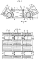
- FIGS. 1, 2 and 2a of the drawing A known traveling grate of the type mentioned above is illustrated in FIGS. 1, 2 and 2a of the drawing.
- the known traveling grate according to FIGS. 1, 2 and 2a contains a closed grate chain 2 which runs endlessly in the direction of arrow 1, the grate links 3 of which are connected to one another via articulated axes 4.
- the grate chain 2 is deflected via deflection elements 5, 6 and is supported in its upper run 2a by a plurality of support rollers 7 arranged closely next to one another.
- the lower run 2b of the grate chain is supported by a smaller number of supporting rollers 8 arranged at correspondingly greater intervals.
- FIG. 1 The section indicated by A in FIG. 1 is illustrated in more detail in FIGS. 2 and 2a. It shows three grate links (3, 3 ', 3 "which are successive in the longitudinal direction of the chain, which are located in the area between two adjacent support rollers 7. All grate links are of the same design, so that only the grate link 3 is explained in more detail below.
- the grate plate 10 contains a good support surface 9, which is only curved flat.
- the front plate end 10a is curved in a circular arc around the hinge axis 11, this circularly curved plate end 10a connecting smoothly and without a step to the slightly curved main part of the plate.
- the rear end 10b of the grate plate 10 is supported on the grate plate 10 "of the following grate member 3".
- Spacer tubes 12, 12 ' are provided on the hinge axes 11, 11'.
- front and rear holding brackets 13 and 14 are screwed to a crossbar 15 on the underside of the grate plate 10.
- the front bracket 13 extends forward to under the spacer tube 12 of the front joint axis 11, while the rear bracket 14 extends rearward under the spacer tube 12 'of the following joint axis 11'.
- the invention is based on the object, avoiding these deficiencies, to design a traveling grate of the type mentioned in such a way that buckling of the grate chain cannot cause any deformation of the rear mounting brackets.
- This object is achieved in that the circular arc-shaped front plate end is extended beyond a reference plane extending approximately vertically through the hinge axis in the horizontal position of the grate plate to the rear to an offset extending across the grate plate and parallel to the hinge axis.
- the inventive extension of the arcuate front plate end ensures that the distance between the rear grate plate end and the adjacent hinge axis does not increase even if the grate chain is buckled. This also maintains the distance between the rear bracket and this hinge axis, and the undesired deformation of the rear bracket explained above is avoided.
- the offset provided according to the invention in the grate plate forms a stop for the rear end of the preceding grate plate when the grate chain is buckled and thus limits the buckling movement to a degree at which the rear bracket is not unduly deformed.
- Each grate link of the grate chain 103 of the traveling grate according to the invention illustrated in FIGS. 3 to 5 contains a grate plate 110, the front end 110a of which is curved in a circular arc around the hinge axis 111 (the geometric center axis M of the hinge axis 111 thus simultaneously represents the center of curvature of the plate end 110a).
- the front plate end 110a curved in a circular arc is now extended beyond a reference plane B to the rear. With the grate plate 110 in a horizontal position, the reference plane B runs approximately vertically through the geometric central axis M of the articulation axis 111.
- the section of the circular arc-shaped plate end 110a lying in front of the reference plane B extends over an angle a of approximately 90 ° and that over the reference plane B. section extended at the rear over an angle ⁇ of at most approximately 30 °, preferably approximately 20 °.
- the extended section of the front plate end 110a which is curved in the shape of a circular arc, is delimited by a bent portion 120 extending across the grate plate 110 and parallel to the hinge axis 111 relative to the central part of the grate plate 110.
- the thickness of the offset 120 corresponds approximately to the thickness of the rear end 110b of the grate plate.
- the structure of the grate chain 103 corresponds to the known embodiment according to FIG. 2.
- the grate plate thus contains a flat, curved support surface 109.
- the rear end 110 of the grate plate slides on the following grate plate 110 '.
- On the underside of the grate plate 110 there is provided a reinforcing rib 115 which runs transversely to the grate member and to which two front holding brackets 113 and a rear holding bracket 114 are screwed. These brackets engage with a little play x the spacer tubes 112 and 112 'of the articulated axes 111, 111'.
- the rear ends (for example 110b ") of the grate plates (for example 110") can extend so far on the associated, arcuate curved front ends (for example 110a) of the following grate plate (for example 110 ) that the distance of the associated rear bracket (eg 114 ") from the associated hinge axis (eg 111) is not changed and in this way an undesired deformation of this bracket is avoided.
- FIG. 5 shows a grate plate 110 in supervision.
- the air passage slots 121 can also be seen, which are parallel to one another and run in the chain longitudinal direction.
- each grate member can contain a grate plate (FIG. 5) or a plurality of grate plates of the same type (FIG. 2a) as required.
- the surfaces of the front and rear grate plate ends which are in sliding contact with one another can be provided with wear inserts 122, 123 made of material with a low coefficient of friction, as is indicated by dashed lines in FIG. 3.
Landscapes
- Engineering & Computer Science (AREA)
- Mechanical Engineering (AREA)
- Chemical & Material Sciences (AREA)
- Geochemistry & Mineralogy (AREA)
- General Engineering & Computer Science (AREA)
- Life Sciences & Earth Sciences (AREA)
- Environmental & Geological Engineering (AREA)
- General Life Sciences & Earth Sciences (AREA)
- Combustion & Propulsion (AREA)
- Geology (AREA)
- Manufacturing & Machinery (AREA)
- Materials Engineering (AREA)
- Metallurgy (AREA)
- Organic Chemistry (AREA)
- Chain Conveyers (AREA)
- Auxiliary Methods And Devices For Loading And Unloading (AREA)
Description
- Die Erfindung betrifft einen Wanderrost mit einer endlos umlaufenden Rostkette, in der aufeinanderfolgende Rostglieder durch Gelenkachsen verbunden sind und je wenigstens eine Rostplatte enthalten, deren vorderes Ende kreisbogenförmig um die Gelenkachse gekrümmt ist und deren hinteres Ende sich gleitend auf dem vorderen Ende der folgenden Rostplatte abstützt, wobei ein auf der Unterseite der Rostplatte vorgesehener, sich nach hinten erstrekkender Haltesteg die zugehörige Gelenkachse mit Spiel untergreift.
- Ein bekannter Wanderrost der vorstehend genannten Art ist in den Fig. 1, 2 und 2a der Zeichnung veranschaulicht.
- Der bekannte Wanderrost gemäß den Fig. 1, 2 und 2a enthält eine in Richtung des Pfeiles 1 endlos umlaufende geschlossene Rostkette 2, deren Rostglieder 3 über Gelenkachsen 4 miteinander verbunden sind. Die Rostkette 2 wird über Umlenkelemente 5, 6 umgelenkt und in ihrem oberen Trum 2a von einer Vielzahl eng nebeneinander angeordneter Tragrollen 7 abgestützt. Das untere Trum 2b der Rostkette wird durch eine kleinere Zahl von in entsprechend größeren Abständen angeordneten Tragrollen 8 abgestützt.
- Der in Fig. 1 mit A angedeutete Ausschnitt ist in den Fig. 2 und 2a näher veranschaulicht. Er zeigt drei in Kettenlängsrichtung aufeinanderfolgende Rostglieder (3, 3', 3", die sich im Bereich zwischen zwei benachbarten Tragrollen 7 befinden. Alle Rostglieder sind gleichartig ausgeführt, so daß im folgenden nur das Rostglied 3 näher erläutert wird.
- Die Rostplatte 10 enthält eine Guttragfläche 9, die nur flach gewölbt ist. Das vordere Plattenende 1 Oa ist kreisbogenförmig um die Gelenkachse 11 gekrümmt, wobei sich dieses kreisbogenförmig gekrümmte Plattenende 10a glatt und ohne Stufe an den leicht gewölbten Hauptteil der Platte anschließt. Das hintere Ende 10b der Rostplatte 10 stützt sich auf der Rostplatte 10" des folgenden Rostgliedes 3" ab.
- Auf den Gelenkachsen 11, 11' sind Distanzrohre 12, 12' vorgesehen. Zur Halterung der Rostplatte an den Gelenkachsen sind auf der Unterseite der Rostplatte 10 an einem Quersteg 15 vordere und hintere Haltewinkel 13 bzw. 14 angeschraubt. Der vordere Haltewinkel 13 erstreckt sich nach vorn bis unter das Distanzrohr 12 der vorderen Gelenkachse 11, während der hintere Haltewinkel 14 nach hinten unter das Distanzrohr 12' der folgenden Gelenkachse 11' reicht. Zwischen den Haltewinkeln 13, 14 und den zugehörigen Distanzrohren 12, 12' soll ein kleines Spiel x vorhanden sein.
- Durch das auf der Rostkette lastende Gut und das Eigengewicht der Kette ergibt sich eine Belastung in Richtung des Pfeiles P, die die Rostkette 2 in ihrem oberen Trum 2a zwischen je zwei aufeinanderfolgenden Tragrollen 7 nach unten durchzuknicken sucht (wie dies durch die Relativstellung der Rostglieder 3, 3', 3" in Fig. 2 angedeutet ist). Betrachtet man nun die sich bei einer solchen Durchknickung ergebende Lageveränderung des hinteren Endes 10b' der Rostplatte 10' gegenüber der Rostplatte 10, so erkennt man, daß sich bei dieser Durchknickbewegung der Abstand des Plattenendes 10b' von der Gelenkachse 11 vergrößert. Dies hat zur Folge, daß der hinterste Teil des Haltewinkels 14 nach unten abgebogen wird, wie dies Fig. 2 zeigt. Kommen dann aufeinanderfolgende Rostglieder wieder in eine geradlinige, nicht abgeknickte Lage (etwa im Bereich, in der die Gelenkachse 11 über eine Tragrolle 7 läuft), so ergibt sich durch die unerwünschte Abbiegung des hinteren Endes des Haltewinkels 14 bzw. 14' ein unerwünscht großes Spiel x. Im unteren Trum der Rostkette können - bedingt durch die großen Abstände der Tragrollen 8 - diese Verformungen der hinteren Haltewinkel 14 so groß werden, daß sie unter Umständen zum Bruch führen.
- Der Erfindung liegt die Aufgabe zugrunde, unter Vermeidung dieser Mängel einen Wanderrost der eingangs genannten Art so auszubilden, daß Durchknickungen der Rostkette keine Verformung der hinteren Haltewinkel verursachen können. Diese Aufgabe wird erfindungsgemäß dadurch gelöst, daß das kreisbogenförmig gekrümmte vordere Plattenende über eine bei horizontaler Lage der Rostplatte etwa vertikal durch die Gelenkachse verlaufende Bezugsebene hinaus nach hinten bis zu einer sich quer über die Rostplatte und parallel zur Gelenkachse erstrekkenden Abkröpfung verlängert ist.
- Die erfindungsgemäße Verlängerung des kreisbogenförmig gekrümmten vorderen Plattenendes (nach hinten über die erwähnte Bezugsebene hinaus) gewährleistet, daß sich auch bei Durchknickungen der Rostkette der Abstand zwischen dem hinteren Rostplattenende und der benachbarten Gelenkachse nicht vergrößert. Damit bleibt auch der Abstand zwischen dem hinteren Haltewinkel und dieser Gelenkachse erhalten, und es wird die oben erläuterte unerwünschte Verformung des hinteren Haltewinkels vermieden.
- Die erfindungsgemäß in der Rostplatte vorgesehene Abkröpfung bildet beim Durchknicken der Rostkette einen Anschlag für das hintere Ende der vorausgehenden Rostplatte und begrenzt damit die Durchknickbewegung auf ein Maß, bei dem der hintere Haltewinkel nicht unzulässig verformt wird.
- Ein Ausführungsbeispiel der Erfindung ist in den Fig. 3 bis 5 der Zeichnung veranschaulicht.
- Jedes Rostglied der Rostkette 103 des in den Fig. 3 bis 5 veranschaulichten erfindungsgemäßen Wanderrostes enthält eine Rostplatte 110, deren vorderes Ende 110a kreisbogenförmig um die Gelenkachse 111 gekrümmt ist (die geometrische Mittelachse M der Gelenkachse 111 stellt also gleichzeitig den Krümmungsmittelpunkt des Plattenendes 110a dar). Das kreisbogenförmig gekrümmte vordere Plattenende 110a ist nun über eine Bezugsebene B hinaus nach hinten verlängert. Die Bezugsebene B verläuft bei horizontaler Lage der Rostplatte 110 etwa vertikal durch die geometrische Mittelachse M der Gelenkachse 111. Der vor der Bezugsebene B liegende Abschnitt des kreisbogenförmig gekrümmten Plattenendes 110a erstreckt sich über einen Winkel a von etwa 90° und der über die Bezugsebene B nach hinten verlängerte Abschnitt über einen Winkel β von höchstens etwa 30°, vorzugsweise etwa 20°.
- Der über die Bezugsebene B nach hinten hinaus verlängerte Abschnitt des kreisbogenförmig gekrümmten vorderen Plattenendes 110a wird durch eine sich quer über die Rostplatte 110 und parallel zur Gelenkachse 111 erstreckende Abkröpfung 120 gegenüber dem mittleren Teil der Rostplatte 110 begrenzt. Die Stärke der Abkröpfung 120 entspricht dabei etwa der Stärke des hinteren Endes 110b der Rostplatte.
- Im übrigen entspricht der Aufbau der Rostkette 103 der bekannten Ausführung gemäß Fig. 2. Die Rostplatte enthält also eine flach gewölbte Guttragfläche 109. Das hintere Ende 110 der Rostplatte gleitet auf der folgenden Rostplatte 110'. Auf der Unterseite der Rostplatte 110 ist eine quer zum Rostglied verlaufende Verstärkungsrippe 115 vorgesehen, an der zwei vordere Haltewinkel 113 und ein hinterer Haltewinkel 114 angeschraubt sind. Diese Haltewinkel untergreifen mit geringem Spiel x die Distanzrohre 112 bzw. 112' der Gelenkachsen 111, 111'.
- Bei einer Durchknickbewegung, wie sie in Fig. 4 veranschaulicht ist, können sich die hinteren Enden (z.B. 110b") der Rostplatten (z.B. 110") so weit auf den zugehörigen, kreisbogenförmig gekrümmten vorderen Enden (z.B. 110a) der folgenden Rostplatte (z.B. 110) verschieben, daß der Abstand des zugehörigen hinteren Haltewinkels (z.B. 114") von der zugehörigen Gelenkachse (z.B. 111) nicht geändert und auf diese Weise eine unerwünschte Verformung dieses Haltewinkels vermieden wird.
- Fig. 5 zeigt eine Rostplatte 110 in Aufsicht. Neben der Anordnung der vorderen und hinteren Haltewinkel 113 bzw. 114 sind auch noch die Luftdurchtrittsschlitze 121 zu erkennen, die parallel zueinander liegen und in Kettenlängsrichtung verlaufen.
- Wie die Fig. 2a und 5 erkennen lassen, kann jedes Rostglied je nach Bedarf eine Rostplatte (Fig. 5) oder mehrere gleichartige Rostplatten (Fig. 2a) enthalten. Die miteinander in Gleitberührung stehenden Flächen der vorderen und hinteren Rostplattenenden können - wie dies in Fig. 3 gestrichelt angedeutet istmit Verschleißeinlagen 122, 123 aus Material mit niedrigem Reibungskoeffizienten versehen sein.
Claims (4)
Applications Claiming Priority (2)
| Application Number | Priority Date | Filing Date | Title |
|---|---|---|---|
| DE2742100A DE2742100C3 (de) | 1977-09-19 | 1977-09-19 | Wanderrost |
| DE2742100 | 1977-09-19 |
Publications (2)
| Publication Number | Publication Date |
|---|---|
| EP0001257A1 EP0001257A1 (de) | 1979-04-04 |
| EP0001257B1 true EP0001257B1 (de) | 1980-01-09 |
Family
ID=6019314
Family Applications (1)
| Application Number | Title | Priority Date | Filing Date |
|---|---|---|---|
| EP78100880A Expired EP0001257B1 (de) | 1977-09-19 | 1978-09-13 | Wanderrost mit endlos umlaufender Rostkette, deren Rostglieder je eine Rostplatte aufweisen |
Country Status (5)
| Country | Link |
|---|---|
| EP (1) | EP0001257B1 (de) |
| JP (1) | JPS587564B2 (de) |
| DE (1) | DE2742100C3 (de) |
| IT (1) | IT1098619B (de) |
| MX (1) | MX147817A (de) |
Families Citing this family (6)
| Publication number | Priority date | Publication date | Assignee | Title |
|---|---|---|---|---|
| JPS5812513U (ja) * | 1981-07-14 | 1983-01-26 | 日立金属株式会社 | コンベア |
| DE3723591A1 (de) * | 1987-07-16 | 1989-01-26 | Gebr Hennig Gmbh | Spaenefoerderer |
| FI111100B (fi) | 2000-01-31 | 2003-05-30 | Outokumpu Oy | Hihna jatkuvatoimiseen materiaalipatjan lämpökäsittelyyn |
| DE102004049912A1 (de) * | 2004-10-13 | 2006-04-20 | Bosch Rexroth Aktiengesellschaft | Gliederkette |
| FI20140286A7 (fi) * | 2014-10-21 | 2016-04-22 | Outotec Finland Oy | Hihna jatkuvatoimisen materiaalikerroksen lämpökäsittelyä varten optimoitujen rei'itysten avulla |
| WO2018091763A1 (en) * | 2016-11-15 | 2018-05-24 | Outotec (Finland) Oy | Conveyor configured to carry and transport a material bed through a furnace and sintering, hardening, or drying equipment |
Family Cites Families (5)
| Publication number | Priority date | Publication date | Assignee | Title |
|---|---|---|---|---|
| DE948048C (de) * | 1953-07-08 | 1956-08-23 | Hauhinco Maschf | Gliederfoerderband |
| US2804834A (en) * | 1954-03-19 | 1957-09-03 | Riley Stoker Corp | Traveling grate stoker |
| DE1758067A1 (de) * | 1968-03-28 | 1970-12-23 | Polysius Ag | Rostplatte fuer Wanderroste |
| DE2109948C3 (de) * | 1971-03-02 | 1974-01-24 | Polysius Ag, 4723 Neubeckum | Wanderrost |
| US3962977A (en) * | 1974-12-23 | 1976-06-15 | Illinois Stoker Company | Grate bar casting for incinerator or other conveyor |
-
1977
- 1977-09-19 DE DE2742100A patent/DE2742100C3/de not_active Expired
-
1978
- 1978-08-25 MX MX174656A patent/MX147817A/es unknown
- 1978-09-13 IT IT27627/78A patent/IT1098619B/it active
- 1978-09-13 EP EP78100880A patent/EP0001257B1/de not_active Expired
- 1978-09-19 JP JP53115029A patent/JPS587564B2/ja not_active Expired
Also Published As
| Publication number | Publication date |
|---|---|
| IT7827627A0 (it) | 1978-09-13 |
| MX147817A (es) | 1983-01-18 |
| JPS587564B2 (ja) | 1983-02-10 |
| EP0001257A1 (de) | 1979-04-04 |
| JPS5455981A (en) | 1979-05-04 |
| DE2742100A1 (de) | 1979-03-29 |
| IT1098619B (it) | 1985-09-07 |
| DE2742100B2 (de) | 1981-02-26 |
| DE2742100C3 (de) | 1981-12-17 |
Similar Documents
| Publication | Publication Date | Title |
|---|---|---|
| DE2321036C3 (de) | Plattenband aus Kunststoff | |
| DE2732460C3 (de) | Verankerungselement zur Arretierung einer Last an einer im Rumpf eines Flugzeugs angebrachten Bodenschiene | |
| DE2359541C3 (de) | Tragplatte für einen Plattenbandförderer | |
| DE2656622C2 (de) | Energieführungskette zur Aufnahme von Energieführungsleitungen | |
| DE69116314T2 (de) | Fördersystem mit Antriebsflächen eines Förderbandmoduls, die im Scharnierbereich mit einem Antriebszahnrad zusammenwirken | |
| EP0793784B1 (de) | Energieführungskette mit führungsanschlag | |
| DE2417516C3 (de) | Vorrichtung bei einer Kette mit Halteranordnungen zum Tragen und zur Führung von einer oder mehreren biegbaren, energieübertragenden Leitungen | |
| DE2232117B2 (de) | Höhen- und neigungsverstellbarer Fahrzeugsitz | |
| DE69801386T2 (de) | Förderer | |
| DE3132317A1 (de) | Transportzahnkette | |
| DE2742100C3 (de) | Wanderrost | |
| DE4124045A1 (de) | Lager- und transportgestell fuer flaechenbauteile | |
| DE202016008741U1 (de) | Modul für ein modulares Förderband mit einer Rollenförderfläche und aus einer Mehrzahl solcher Module gebildetes modulares Förderband | |
| DE2317361B1 (de) | Rollenumlauflager fuer rollbahnen | |
| DE2759636C2 (de) | Schleppkette für ein Schleppkettenfördersystem | |
| WO1998040683A1 (de) | Lagervorrichtung für den beweglichen teil eines kühl- oder feuerungsrosts | |
| DE3541364A1 (de) | Tragglied fuer gliederbandfoerderer | |
| CH324107A (de) | Fördereinrichtung für Behälter, mit einer endlosen Kette | |
| DE923777C (de) | Foerdereinrichtung fuer Behaelter mit einer endlosen Kette | |
| DE889537C (de) | Rollkettenanordnung | |
| EP0050720B1 (de) | Fallklappenschacht für Selbstverkäufer | |
| DE2516818C2 (de) | Kettenförderer | |
| DE976834C (de) | Stahlglieder-Foerderband mit Seitenketten und Laufrollen | |
| AT398879B (de) | Fördervorrichtung | |
| DE482263C (de) | Backofen mit durch eine Zwischendecke voneinander getrennten Backraeumen, in denen je ein Wanderherd sich im Kreislauf bewegt |
Legal Events
| Date | Code | Title | Description |
|---|---|---|---|
| PUAI | Public reference made under article 153(3) epc to a published international application that has entered the european phase |
Free format text: ORIGINAL CODE: 0009012 |
|
| AK | Designated contracting states |
Designated state(s): CH FR GB |
|
| 17P | Request for examination filed | ||
| GRAA | (expected) grant |
Free format text: ORIGINAL CODE: 0009210 |
|
| AK | Designated contracting states |
Designated state(s): CH FR GB |
|
| PGFP | Annual fee paid to national office [announced via postgrant information from national office to epo] |
Ref country code: BE Payment date: 19811231 Year of fee payment: 4 |
|
| PGFP | Annual fee paid to national office [announced via postgrant information from national office to epo] |
Ref country code: FR Payment date: 19890807 Year of fee payment: 12 |
|
| PGFP | Annual fee paid to national office [announced via postgrant information from national office to epo] |
Ref country code: CH Payment date: 19890811 Year of fee payment: 12 |
|
| PGFP | Annual fee paid to national office [announced via postgrant information from national office to epo] |
Ref country code: GB Payment date: 19890831 Year of fee payment: 12 |
|
| PG25 | Lapsed in a contracting state [announced via postgrant information from national office to epo] |
Ref country code: GB Effective date: 19900913 |
|
| PG25 | Lapsed in a contracting state [announced via postgrant information from national office to epo] |
Ref country code: CH Effective date: 19900930 |
|
| GBPC | Gb: european patent ceased through non-payment of renewal fee | ||
| PG25 | Lapsed in a contracting state [announced via postgrant information from national office to epo] |
Ref country code: FR Effective date: 19910530 |
|
| REG | Reference to a national code |
Ref country code: CH Ref legal event code: PL |
|
| REG | Reference to a national code |
Ref country code: FR Ref legal event code: ST |
|
| PLBE | No opposition filed within time limit |
Free format text: ORIGINAL CODE: 0009261 |
|
| STAA | Information on the status of an ep patent application or granted ep patent |
Free format text: STATUS: NO OPPOSITION FILED WITHIN TIME LIMIT |