EP0001336B1 - Dispositif de suspension et de commande de porte pour enceinte sous pression - Google Patents
Dispositif de suspension et de commande de porte pour enceinte sous pression Download PDFInfo
- Publication number
- EP0001336B1 EP0001336B1 EP78300348A EP78300348A EP0001336B1 EP 0001336 B1 EP0001336 B1 EP 0001336B1 EP 78300348 A EP78300348 A EP 78300348A EP 78300348 A EP78300348 A EP 78300348A EP 0001336 B1 EP0001336 B1 EP 0001336B1
- Authority
- EP
- European Patent Office
- Prior art keywords
- door
- shaft
- opening
- support member
- movement
- Prior art date
- Legal status (The legal status is an assumption and is not a legal conclusion. Google has not performed a legal analysis and makes no representation as to the accuracy of the status listed.)
- Expired
Links
- 230000008878 coupling Effects 0.000 claims description 11
- 238000010168 coupling process Methods 0.000 claims description 11
- 238000005859 coupling reaction Methods 0.000 claims description 11
- 238000007789 sealing Methods 0.000 claims description 11
- 238000006073 displacement reaction Methods 0.000 claims description 5
- 239000011435 rock Substances 0.000 claims 2
- 230000007246 mechanism Effects 0.000 description 8
- 238000007373 indentation Methods 0.000 description 7
- 238000010411 cooking Methods 0.000 description 4
- 238000010276 construction Methods 0.000 description 3
- 230000000694 effects Effects 0.000 description 3
- 238000003780 insertion Methods 0.000 description 3
- 230000037431 insertion Effects 0.000 description 3
- 238000003466 welding Methods 0.000 description 3
- 150000001875 compounds Chemical class 0.000 description 2
- 230000006835 compression Effects 0.000 description 2
- 238000007906 compression Methods 0.000 description 2
- 238000004519 manufacturing process Methods 0.000 description 2
- 230000013011 mating Effects 0.000 description 2
- 238000000034 method Methods 0.000 description 2
- 230000009471 action Effects 0.000 description 1
- 239000002783 friction material Substances 0.000 description 1
- 238000010438 heat treatment Methods 0.000 description 1
- 230000006872 improvement Effects 0.000 description 1
- 230000004048 modification Effects 0.000 description 1
- 238000012986 modification Methods 0.000 description 1
- 230000002093 peripheral effect Effects 0.000 description 1
- 238000002360 preparation method Methods 0.000 description 1
- 230000004044 response Effects 0.000 description 1
- 230000000284 resting effect Effects 0.000 description 1
Images

Classifications
-
- B—PERFORMING OPERATIONS; TRANSPORTING
- B01—PHYSICAL OR CHEMICAL PROCESSES OR APPARATUS IN GENERAL
- B01J—CHEMICAL OR PHYSICAL PROCESSES, e.g. CATALYSIS OR COLLOID CHEMISTRY; THEIR RELEVANT APPARATUS
- B01J3/00—Processes of utilising sub-atmospheric or super-atmospheric pressure to effect chemical or physical change of matter; Apparatus therefor
- B01J3/03—Pressure vessels, or vacuum vessels, having closure members or seals specially adapted therefor
-
- F—MECHANICAL ENGINEERING; LIGHTING; HEATING; WEAPONS; BLASTING
- F16—ENGINEERING ELEMENTS AND UNITS; GENERAL MEASURES FOR PRODUCING AND MAINTAINING EFFECTIVE FUNCTIONING OF MACHINES OR INSTALLATIONS; THERMAL INSULATION IN GENERAL
- F16J—PISTONS; CYLINDERS; SEALINGS
- F16J13/00—Covers or similar closure members for pressure vessels in general
- F16J13/16—Pivoted closures
- F16J13/18—Pivoted closures pivoted directly on the frame
Definitions
- the present invention relates to means for sealing pressure vessels, and more particularly, to door mounting and actuating apparatus for a door of the warped expandable type.
- the door mounting and actuating apparatus embodying the present invention in its preferred form, is directed to utilization with pressure vessels of the type disclosed in U.S. Patent No. 2,094,212 and No. 3,961,817 and No. 3,409,164 and assigned to the assignee of this application. These pressure vessels are used for food preparation in restaurants and institutional kitchens and employ a generally disc-shaped access door which is stressed initially so as to be warped on a diameter.
- the door is positioned inside the pressure vessel which has a circular access opening slightly smaller in diameter than the non-warped diameter of the door.
- Door warp facilitates insertion of the door through the access opening, and after insertion through the access opening the door is stressed against an interior rim of the access opening to expand the door and achieve an air tight seal.
- the door is flexed to remove the warp and assume the configuration of a spherical section of circular outline.
- the door is moved from a contracted position in which it can be passed through the opening into an expanded position where it seals against the inner walls of the pressure vessel.
- the means for mounting the door at the exterior of the pressure vessel must provide for shifting the door back and forth laterally in order for it to pass through the opening and then be centered within the access opening, so that it can be brought against the internal surfaces of the pressure vessel to expand into sealing engagement with the walls of the pressure vessel.
- the movement may be provided by a cam device as shown in Vischer U.S. Patent No. 2,904,212, a worm and crank arrangement as shown in Vischer U.S. Patent No. 3,409,164, or a camming assembly of the type shown in Shrimsher U.S. Patent No. 3,961,817.
- the present invention provides an improvement over the above referred to door closure mechanisms for pressure vessels by providing apparatus whereby the necessary compound movements of the door can be achieved with only vertical force being applied to the handle or lever utilized to manually activate the apparatus.
- door mounting and actuating apparatus for a warped expandable door that is movable in its warped condition into a pressure vessel through an opening therein, comprising: an elongate door support member for hinging to the pressure vessel and supporting the door for swinging movement through the opening; a rotatable member mounted on the door support member; a member slidable relative to the door support member and for carrying the door; coupling means connecting the rotatable member and the slidable member in such a way that rotation of the rotatable member causes the slidable member to move relative to the door support member in both a first direction to produce lateral displacement of the door for centring the door with the opening after passing the door through the opening and in a second direction .
- substantially perpendicular to the first direction to produce substantially translational displacement of the door for bringing the door against the interior rim of the opening then expanding it and finally sealing it against the interior rim such apparatus being known from the U.S.
- Patent No. 3,961,817 the invention being characterised in that: the rotatable member is a shaft mounted along the length of the door support member for axial movement relative thereto; and cam and follower means are operably associated with the shaft such that rotation of the shaft causes axial movement thereof; and the coupling means transmit this axial movement of the shaft to the slidable member to move it in the first direction; and the coupling means transform the rotational movement of the shaft into a movement of the slidable member in the second direction.
- the door Since the door is warped so that it will contract usually in a vertical direction, it is desirable to provide means for canting the door relative to its support member when the door is open to allow easy entry of the door through the opening, and for aligning the door with the opening when the door is in position to be expanded into sealing engagement with the inside walls, e.g., the rim of the pressure vessel around the opening.
- one end of the shaft is provided with a handle, and the opposite end of the shaft is provided with a crank member which in turn is connected to a sliding member comprising a rod to which the center of the door is secured, and the rod is held in a cylindrical guide on the support member.
- rotation of the shaft by the handle causes the rod to move toward or away from the door support member so that the door will engage or disengage the interior seal of the pressure vessel.
- the cylindrical guide is carried by the door support member in such a manner that the guide, rod and door can move axially of the shaft, from a position where the door is centered in the access opening to a position where it is offset from the center of the access opening and can be canted for removal through the opening upon pivoting of the support member.
- a spring plate is secured between the support member and the guide and biases the rod and guide so as to cant the door while it is in the contracted position where it will pass through the opening. Upon axial movement of the shaft the plate will yield to align the door properly with the access opening.
- the handle used to rotate the shaft is located to one side of the opening, and is preferably rotatable through approximately 170°C from a "door open” position disposed substantially vertically upward to a downwardly extending position, preferably slightly outward from a vertical plane through the axis of the shaft, when the door is closed and sealed.
- This positioning of the handle produces a tendency for the operator to exert substantially downward (as distinguished from sideward or rearward) force when the major effort is needed to close the door.
- the cam surface is preferably designed with a slight indentation or detent in the fully closed position which tends to maintain the door closed.
- the portion of the cam surface following the detent is substantially flat since rotation of the handle during this part of cam follower engagement causes the rod and door to move inwardly of the pressure vessel away from the support member.
- the plate causes the door to cant slightly, such that the edge of the door closest to the pivot point moves away from the door support member.
- the last portion of the cam surface is shaped so that the shaft will be shifted axially to move the access door laterally off the center of the opening when the handle is rotated to the open position.
- the cam/follower mechanism is used for door shifting and locating, and the crank/rod mechanism produces the closing and sealing force.
- the crank is adjustable to accommodate tolerance in the door construction and movement between warped and unwarped positions.
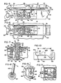
- the door mounting and actuating apparatus embodying the present invention is utilized to close the access opening on a steam cooker having a housing shown generally as 10 in Fig. 1.
- a steam cooker having a housing shown generally as 10 in Fig. 1.
- Such cookers are commonly utilized in the restaurant and commercial cooking establishments for rapidly cooking or heating food.
- the access opening 12 of the pressure vessel is supported in the front surface panel of the housing, and is generally circular, provided with a rim 13 and an internal seal member 14 in the form of an O-ring. Seal member 14 is mounted around the entire periphery of the access opening on the inside wall 16 to seal the door during cooking.
- the door 18 is generally disc-shaped, warped during fabrication so as to contract in the vertical dimensions unless the door is pressed against the seal member 14 on the inside of the steam cooker. Construction of the door is well known and is referred to in the above referenced U.S. patents and forms no part of the present invention.
- this particular construction provides a contractible door which allows insertion of the door through the access opening.
- the door must be able to contract along a diameter sufficiently to pass through the access opening the subsequently to expand inside the access opening.
- the door is supported from a hinged position adjacent the access opening it is helpful to cant the door slightly so that its larger dimension (when warped) can pass freely through the access opening.
- the door is pivotally supported on the front of the housing 10 by the mounting and actuating apparatus shown generally as 20.
- This apparatus has a main door support member 22 in the form of a channel, generally U-shaped in vertical cross section, opening outward away from the door.
- the end portion 24 of this channel is pivotally secured by pin 26 to a hinge bracket 28 mounted to the side of the pressure vessel and extending through the front surface of the housing 10.
- the end portion 24 is provided with a hinge plate 30 which engages the hinge bracket 28 so as to pivot horizontally about the vertical pin 26.
- Hinge plate 30 is secured to the back portion 31 of the channel-shaped main support member 22 by welding or the like.
- a decorative cover 32 also generally channel-shaped in cross section, but slightly larger than main support member 22, is provided to enclose the door latch mechanism of the apparatus. Cover 32 is placed over support member 22 with the opening disposed inwardly towards the door and is secured to the main support member 32 with a plurality of screws (not shown) in order to permit the cover to be removed for servicing of the door latch mechanism.
- the door 18 is secured to the door mounting and actuating apparatus 20 by a cylindrical sliding member comprising a rod 34 as best seen in Fig. 7.
- a closed nut or end cap 36 is threaded onto the end portion of rod 34 and holds the door 18 against an annular shelf or seat 40 on the rod.
- An 0-ring seal 42 is provided between door 18 and nut 36 to prevent loss of pressure through the opening 38 in the door.
- Rod 34 is supported in a cylindrical guide 44 for inward and outward movement relative to the access opening of the steam cooker.
- a ball detent member 45 is threaded into the side of guide 44 and a mating indentation in the side of rod 34 is provided to prevent rotation of the rod and the door.
- the guide 44 is secured (as by welding) to a plate 46, which in turn is yieldingly supported on the back surface 31 of main support member 22 by bolts 48 which are provided with compression springs 50.
- Plate 46 is a rectangular flat plate which is bent slightly at its end portion 52, where it is mounted by bolts 48 to the back of support member 22.
- the bent portion 52 provides a fulcrum point such that when the rod and the door 18 move away from the back of support member 22, plate 46 will cant slightly, thus causing the rod 34 and door 18 to also be canted slightly so that the edge portion 54 of the door closest to the pivotal end portion 24 of the apparatus 20 will be farther away from the support member 22 than the opposite edge portion 56.
- the degree of cant necessary in order to permit to door to be inserted through the access opening in the steam cooker will depend upon several factors such as the diameter of the door, diameter of the access opening, swinging radius from the pivot point of the door latch mechanism, and the contracted vertical dimension of the door. For example, using an eight inch diameter door a cant of approximately 4.5 degrees has proved satisfactory when the pivot is approximately five inches from the center of the door.
- Plate 46 must also be movable laterally of the main support member 22 to accommodate displacement of the rod and door to and from a position horizontally offset in the direction of the pivot or hinge from the center line of the access opening, to allow the door to move freely through the steam cooker when the apparatus 20 is pivoted about pin 26.
- the openings in the plate 46, through which bolts 48 extend are in the form of elongated slots which permit the plate, rod and door to be shifted laterally by a further portion of the apparatus 20, described below.
- a main drive shaft 60 is provided.
- Shaft 60 is supported on main support member 22 by a pair of horizontally spaced brackets 62 and 64 so that the drive shaft is disposed with its longitudinal axis extending horizontally and parallel to the back 31 or main support member 22.
- Shaft 60 is so supported by brackets 62 and 64 that it can be both rotated and moved translationally along its axis.
- a crank member 66 is secured to one end of shaft 60, and rod 34 is connected to the crank member 66 through an adjustable connecting rod 68.
- Connecting rod 68 is composed of several parts.
- One part 70 is pivotally secured to a pin 72 mounted in rod 34, so that part 70 will pivot in a vertical plane upon rotation of crank member 66.
- Another part 74 is threaded at one end onto part 70, to provide a means for adjusting the length of the connecting rod 68, and has its opposite end mounted on a spherical bearing member 76 which permits angular movement of part 74 relative to the crank member 66.
- the spherical bearing member 76 is mounted to the outer end of crank 66 by bolt 78. Rotation of crank member 66 by shaft 60 will thus cause longitudinal movement of rod 34, to carry door 18 toward and away from the support member 22.
- the spherical bearing member 76, and the loose connection between pin 72 and part 70 permit the piston and the door to be canted by plate 46.
- a cam and follower mechanism shown generally as 90, is utilized.
- the cam follower 92 is a ball bearing roller mounted for rotation on an arm 94 extending perpendicular to the drive shaft 60 and clamped thereto.
- the follower 92 moves in a circular path in a plane perpendicular to the axis of drive shaft 60.
- the cam member 96 is cylindrical in form and secured to main support member 22, such as by welding it to bracket 64.
- the cam member 96 includes a cam surface 98 in line with the follower 92, which is urged into contact with the cam surface 98 by a compression spring 100 disposed concentrically around the shaft 60 and maintained in a compressed state by engagement at one end with bracket 62, and at the other end with arm 94.
- cam surface 98 is shown in Fig. 10.
- follower 92 is in position 92a in Fig. 10.
- a slight indentation or detent 102 in the cam surface 98 is provided in this position so that an initial force must be applied to shaft 60 to move the follower 92 up out of the indentation 102.
- This indentation 102 prevents the door from opening due to a decrease in pressure or a negative pressure within the steam cooker 10 as often occurs at the end of a cooking cycle.
- follower 92 moves along the flat central portion 104 of camming surface 98, while rod 34 is moved inwardly relative to the steam cooker 10 by crank 66, thus releasing the edges of the door from their sealing engagement around the access opening.
- roller member 92 moves to position 92c in Fig. 10.
- a handle 110 is secured to the outer end of shaft 60 by means of coupling member 112, as best seen in Fig. 8.
- the outer end of shaft 60 has a rectangular cross section on which is fitted a coupling member 112 with corresponding mating opening.
- the member 112 has a threaded transverse hole in which handle 110 is threaded to engage the end portion of shaft 60, holding the coupling member 112 and the handle 110 in place.
- the handle 110 is so disposed that when the door is in the closed position handle 110 will extend vertically downward.
- cam surface 98 is so designed that shaft 60 is permitted to rotate through substantially 170 degrees. This results in handle 110 being disposed 10 degrees off of vertical when the door is in the fully open position.
- handle 110 being disposed 10 degrees off of vertical when the door is in the fully open position.
- the angular relation of follower 92 and crank 66, with respect to the longitudinal axis of shaft 60, is such that crank 66 is somewhat over-center when the door is fully closed. This precludes movement of the door in response to negative pressures in the vessel as may occur at the end of an operating cycle.
- handle 110 is rotated upward, outwardly away from the front face of the housing 10. This movement causes follower 92 to be rotated out of the cam indentation 102 onto cam surface 104 while crank 66 moves rod 34, and thus door 18, towards the interior of the vessel. As rotation of handle 110 is continued and follower 92 proceeds along the flat cam surface 104, rod 34 continues to move towards the interior of the vessel allowing door 18 to again warp to its contracted position.
- spring plate 46 begins to cant the rod 34, and thus door 18, so that the end portion 54 of the door adjacent the pivotal position of the apparatus 20 is farthest away from the door support member 22.
- Fig. 11 shows an alternate embodiment of the invention wherein the mounting of the cam follower and the cam of the preferred embodiment are reversed.
- Cam 90a is mounted to the shaft 60 and is rotated by movement of the handle 110, while the cam follower 92a is mounted stationary on the main support member 32.
- the cam follower 92a is a sliding follower instead of the roller shown in Figs. 3-10, and may be built of suitable low friction materials. In a small steam cooker, wherein the door may be of about six inches diameter, and the forces needed to move the door are therefore smaller, this modification may be desirable for lower manufacturing cost.
Landscapes
- Engineering & Computer Science (AREA)
- General Engineering & Computer Science (AREA)
- Chemical & Material Sciences (AREA)
- Mechanical Engineering (AREA)
- Organic Chemistry (AREA)
- Chemical Kinetics & Catalysis (AREA)
- Pressure Vessels And Lids Thereof (AREA)
Claims (11)
Applications Claiming Priority (2)
| Application Number | Priority Date | Filing Date | Title |
|---|---|---|---|
| US833720 | 1977-09-16 | ||
| US05/833,720 US4096968A (en) | 1977-09-16 | 1977-09-16 | Door mounting and actuator for a pressure vessel |
Publications (2)
| Publication Number | Publication Date |
|---|---|
| EP0001336A1 EP0001336A1 (fr) | 1979-04-04 |
| EP0001336B1 true EP0001336B1 (fr) | 1981-12-02 |
Family
ID=25265103
Family Applications (1)
| Application Number | Title | Priority Date | Filing Date |
|---|---|---|---|
| EP78300348A Expired EP0001336B1 (fr) | 1977-09-16 | 1978-09-05 | Dispositif de suspension et de commande de porte pour enceinte sous pression |
Country Status (4)
| Country | Link |
|---|---|
| US (1) | US4096968A (fr) |
| EP (1) | EP0001336B1 (fr) |
| CA (1) | CA1078311A (fr) |
| DE (1) | DE2861407D1 (fr) |
Families Citing this family (15)
| Publication number | Priority date | Publication date | Assignee | Title |
|---|---|---|---|---|
| US4188869A (en) * | 1977-02-23 | 1980-02-19 | Van Den Bergh Engineering Limited | Door for a steam peeler |
| US4253600A (en) * | 1978-05-03 | 1981-03-03 | Standard Oil Company (Indiana) | Fast food container |
| IT7921160V0 (it) * | 1979-03-22 | 1979-03-22 | Bertola Amalia | Dispositivo di bloccaggio del coperchio di una pentola apressione atto ad impedirne l'apertura in presenza di pressione relativa interna. |
| US4239602A (en) * | 1979-07-23 | 1980-12-16 | Insul Company, Inc. | Ascension pipe elbow lid for coke ovens |
| GR72928B (fr) * | 1979-11-23 | 1984-01-12 | Kunz Paul | |
| DE3302109A1 (de) * | 1983-01-22 | 1984-08-09 | Hubert Eirich | Vorrichtung zum verschliessen und kontinuierlichen entleeren des behaelters einer aufbereitungsmaschine |
| US4823977A (en) * | 1988-07-06 | 1989-04-25 | Mueller Co. | Abandoning plug for hose nozzle |
| DE19956939A1 (de) * | 1999-11-26 | 2001-05-31 | Eirich Maschf Gustav | Vorrichtung und Verfahren zum Verschließen einer Entleeröffnung in einem drehenden Behälter |
| US6611993B2 (en) * | 2000-06-02 | 2003-09-02 | Francis M. Ray | Hinge mechanism |
| US6454117B1 (en) * | 2001-01-04 | 2002-09-24 | Taylor Forge Engineered Systems, Inc. | Manway for pressure vessels |
| ITTO20060119A1 (it) * | 2006-02-21 | 2007-08-22 | Valmar Global Vse Za Sladoled D O O | Macchina per la produzione di gelato artigianale ed affini |
| US8146770B2 (en) * | 2007-06-19 | 2012-04-03 | Duncan Newman | Adjustable closure for a container |
| US20130101372A1 (en) * | 2011-10-19 | 2013-04-25 | Lam Research Ag | Method and apparatus for processing wafer-shaped articles |
| DK2834144T3 (da) * | 2012-04-04 | 2016-11-21 | Beacon Finland Ltd Oy | Apparat, indretning og fremgangsmåde til låsning af en luge under vand eller anden aftagelig struktur |
| DE112015000239B4 (de) * | 2014-05-06 | 2025-09-11 | Amixon Gmbh | Vorrichtung zur Aufnahme und Abgabe von mischbaren Materialien |
Family Cites Families (6)
| Publication number | Priority date | Publication date | Assignee | Title |
|---|---|---|---|---|
| FR639195A (fr) * | 1927-01-13 | 1928-06-15 | Cie Des Forges D Audincourt Et | Perfectionnements aux marmites ou récipients autoclaves |
| DE744442C (de) * | 1942-07-24 | 1950-10-03 | Karl G Schmidt | Selbstdichtender Verschluss fuer Druckgefaesse |
| BE495253A (fr) * | 1947-12-29 | |||
| US2904212A (en) * | 1956-07-31 | 1959-09-15 | William Vischer | Pressurized vessel |
| US3045861A (en) * | 1959-12-01 | 1962-07-24 | Wesley E Dieter | Closure for evacuated and/or pressurized vessel |
| US3961817A (en) * | 1974-12-23 | 1976-06-08 | Hobart Corporation | Door latch for a pressure vessel |
-
1977
- 1977-09-16 US US05/833,720 patent/US4096968A/en not_active Expired - Lifetime
-
1978
- 1978-07-10 CA CA307,099A patent/CA1078311A/fr not_active Expired
- 1978-09-05 EP EP78300348A patent/EP0001336B1/fr not_active Expired
- 1978-09-05 DE DE7878300348T patent/DE2861407D1/de not_active Expired
Also Published As
| Publication number | Publication date |
|---|---|
| DE2861407D1 (en) | 1982-01-28 |
| US4096968A (en) | 1978-06-27 |
| EP0001336A1 (fr) | 1979-04-04 |
| CA1078311A (fr) | 1980-05-27 |
Similar Documents
| Publication | Publication Date | Title |
|---|---|---|
| EP0001336B1 (fr) | Dispositif de suspension et de commande de porte pour enceinte sous pression | |
| US5670025A (en) | Coke oven door with multi-latch sealing system | |
| US3812742A (en) | Jar opener | |
| EP3406947B1 (fr) | Clapet | |
| CA2120211A1 (fr) | Soupape a disque | |
| KR20200071726A (ko) | 조리 냄비의 빠른 교체를 구현하는 플랜지 어셈블리 및 이 플랜지 어셈블리를 이용한 조리 냄비 조합 장치 | |
| US5313738A (en) | Closure for doors used with small and medium sized pressure vessels | |
| US4809542A (en) | Leak testing device for pressure vessels | |
| US2337948A (en) | Door hinge | |
| JPH0516282B2 (fr) | ||
| US2966999A (en) | Pressure cooker closure | |
| CN213757933U (zh) | 排浆阀和食品加工机 | |
| CN118327406B (zh) | 一种门体铰链动力机构 | |
| CN114486143A (zh) | 一种跌落测试装置 | |
| CN219221436U (zh) | 高温高压金属硬密封蝶阀 | |
| US3961817A (en) | Door latch for a pressure vessel | |
| CN210950128U (zh) | 一种用于灶具气密性检测的阀门自动开启及关闭装置 | |
| US4230532A (en) | Oven door | |
| JPH0510902Y2 (fr) | ||
| US2296313A (en) | Internal closure and means for operating same | |
| US2587947A (en) | Arrangement for maintaining a closure in any of a plurality of open positions | |
| US3052345A (en) | Lunch bucket | |
| CN220931720U (zh) | 一种密闭式可调气氛炉 | |
| KR101879541B1 (ko) | 과회전 방지식 버터플라이 밸브 | |
| US2904212A (en) | Pressurized vessel |
Legal Events
| Date | Code | Title | Description |
|---|---|---|---|
| PUAI | Public reference made under article 153(3) epc to a published international application that has entered the european phase |
Free format text: ORIGINAL CODE: 0009012 |
|
| AK | Designated contracting states |
Designated state(s): DE FR GB |
|
| 17P | Request for examination filed | ||
| GRAA | (expected) grant |
Free format text: ORIGINAL CODE: 0009210 |
|
| AK | Designated contracting states |
Designated state(s): DE FR GB |
|
| REF | Corresponds to: |
Ref document number: 2861407 Country of ref document: DE Date of ref document: 19820128 |
|
| KL | Correction list |
Free format text: 82/04 ZEICHNUNG |
|
| REG | Reference to a national code |
Ref country code: GB Ref legal event code: 732 |
|
| PGFP | Annual fee paid to national office [announced via postgrant information from national office to epo] |
Ref country code: FR Payment date: 19940613 Year of fee payment: 17 |
|
| PGFP | Annual fee paid to national office [announced via postgrant information from national office to epo] |
Ref country code: DE Payment date: 19940615 Year of fee payment: 17 |
|
| PGFP | Annual fee paid to national office [announced via postgrant information from national office to epo] |
Ref country code: GB Payment date: 19940616 Year of fee payment: 17 |
|
| PG25 | Lapsed in a contracting state [announced via postgrant information from national office to epo] |
Ref country code: GB Effective date: 19950905 |
|
| GBPC | Gb: european patent ceased through non-payment of renewal fee |
Effective date: 19950905 |
|
| PG25 | Lapsed in a contracting state [announced via postgrant information from national office to epo] |
Ref country code: FR Effective date: 19960531 |
|
| PG25 | Lapsed in a contracting state [announced via postgrant information from national office to epo] |
Ref country code: DE Effective date: 19960601 |
|
| REG | Reference to a national code |
Ref country code: FR Ref legal event code: ST |
|
| PLBE | No opposition filed within time limit |
Free format text: ORIGINAL CODE: 0009261 |
|
| STAA | Information on the status of an ep patent application or granted ep patent |
Free format text: STATUS: NO OPPOSITION FILED WITHIN TIME LIMIT |