EP0001337A1 - Radanordnung und Montage - Google Patents
Radanordnung und Montage Download PDFInfo
- Publication number
- EP0001337A1 EP0001337A1 EP78300355A EP78300355A EP0001337A1 EP 0001337 A1 EP0001337 A1 EP 0001337A1 EP 78300355 A EP78300355 A EP 78300355A EP 78300355 A EP78300355 A EP 78300355A EP 0001337 A1 EP0001337 A1 EP 0001337A1
- Authority
- EP
- European Patent Office
- Prior art keywords
- trailer
- mounting assembly
- wheel mounting
- arms
- vehicle
- Prior art date
- Legal status (The legal status is an assumption and is not a legal conclusion. Google has not performed a legal analysis and makes no representation as to the accuracy of the status listed.)
- Withdrawn
Links
- 230000000712 assembly Effects 0.000 claims description 11
- 238000000429 assembly Methods 0.000 claims description 11
- 230000006835 compression Effects 0.000 claims description 4
- 238000007906 compression Methods 0.000 claims description 4
- 239000000463 material Substances 0.000 claims description 2
- 238000003466 welding Methods 0.000 claims description 2
- 238000006073 displacement reaction Methods 0.000 claims 1
- 239000000725 suspension Substances 0.000 description 11
- 239000000969 carrier Substances 0.000 description 4
- 238000010276 construction Methods 0.000 description 2
- 229910000831 Steel Inorganic materials 0.000 description 1
- 230000008878 coupling Effects 0.000 description 1
- 238000010168 coupling process Methods 0.000 description 1
- 238000005859 coupling reaction Methods 0.000 description 1
- 238000006880 cross-coupling reaction Methods 0.000 description 1
- 238000003780 insertion Methods 0.000 description 1
- 230000037431 insertion Effects 0.000 description 1
- 239000002184 metal Substances 0.000 description 1
- 238000000034 method Methods 0.000 description 1
- 239000010959 steel Substances 0.000 description 1
Images


Classifications
-
- B—PERFORMING OPERATIONS; TRANSPORTING
- B62—LAND VEHICLES FOR TRAVELLING OTHERWISE THAN ON RAILS
- B62D—MOTOR VEHICLES; TRAILERS
- B62D21/00—Understructures, i.e. chassis frame on which a vehicle body may be mounted
- B62D21/02—Understructures, i.e. chassis frame on which a vehicle body may be mounted comprising longitudinally or transversely arranged frame members
- B62D21/04—Understructures, i.e. chassis frame on which a vehicle body may be mounted comprising longitudinally or transversely arranged frame members single longitudinal type
-
- B—PERFORMING OPERATIONS; TRANSPORTING
- B60—VEHICLES IN GENERAL
- B60G—VEHICLE SUSPENSION ARRANGEMENTS
- B60G3/00—Resilient suspensions for a single wheel
- B60G3/02—Resilient suspensions for a single wheel with a single pivoted arm
- B60G3/04—Resilient suspensions for a single wheel with a single pivoted arm the arm being essentially transverse to the longitudinal axis of the vehicle
- B60G3/06—Resilient suspensions for a single wheel with a single pivoted arm the arm being essentially transverse to the longitudinal axis of the vehicle the arm being rigid
-
- B—PERFORMING OPERATIONS; TRANSPORTING
- B60—VEHICLES IN GENERAL
- B60G—VEHICLE SUSPENSION ARRANGEMENTS
- B60G7/00—Pivoted suspension arms; Accessories thereof
- B60G7/02—Attaching arms to sprung part of vehicle
Definitions
- This invention relates to a wheel mounting assembly and more particularly but not solely to a wheel mounting assembly suitable for attaching a wheel to a semi-trailer so as to permit the provision of fully independent suspension.
- Heavy goods semi-trailers of the type which are articulated to a tractor vehicle by means of a so called fifth wheel coupling generally employ an axle which extends transversely of the chassis to support a wheel on each side of the chassis.
- Such configurations have employed various methods of springing but the beam axle connection between wheels prevents the provision of fully independent suspension.
- This invention seeks to provide a wheel mounting assembly configuration suitable for mounting wheels onto heavy goods semi-trailers, in a manner which permits the provision of fully independent suspension, which configuration is also suitable for use in other applications e.g. for light weight trailers and on vehicles themselves.
- the main advantage offered by the invention is the provision of a simple wheel mounting assembly which is particularly suitable for adaption to independent suspension and which can be produced in a form suitable for use with heavy goods trailers.
- a wheel mounting assembly comprising a stub axle having two pairs of arms in which the arms of each pair extend in wishbone configuration one to each of two sides of the stub axle from positions at or near opposite ends of the stub axle the free ends of the arms being adapted for pivotal mounting on a chassis.
- the arms are preferably permanently connected to the stub axle by for example welding.
- the free ends of the two arms on each side of the stub axle are preferably rigidly coupled to a common carrier member.
- the two carrier members may be adapted for pivotal mounting on a common axis.
- the arms at one end of the stub axle may be of equal length as may the arms at the other end of the stub axle.
- the arms mounted at the end of the stub axle which in use extends inboard of the trailer are normally shorter than the arms mounted at the opposite end of the stub axle.
- the invention also includes a vehicle or trailer provided with wheels each mounted by mounting assemblies as hereinbefore defined which mounting assemblies are pivotally mounted on the chassis of the vehicle or trailer by the adaption at the free ends of the arms.
- a vehicle or trailer may have a single longitudinally extending beam chassis with the mounting assemblies pivotally mounted on the beam by the adaption at the free ends of the arms
- the wheel mounting assemblies may be "sprung" by any suitable resilient means acting between the wheel mounting assembly and the vehicle or trailer chassis.
- a fully independent resilient means is provided for each wheel mounting assembly e.g. a pressure diaphragm or bellows containing air under compression, or adapted for connection to a pressurized source e.g. a compressor on a vehicle; a leaf or coil spring arrangement or rubber cones.
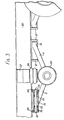
- the wheel mounting assembly of Figure 1 is constructed of box section tubular steel material and has a stub axle 10 for mounting a wheel by means of a hub not shown.
- a stub axle 10 for mounting a wheel by means of a hub not shown.
- Welded to two opposite sides of the stub axle towards the hub end are two arms 11 of equal length.
- the arms 11 are divergent to form a wishbone configuration.
- Another pair of similar but shorter arms 12 of equal length are welded to the same opposite sides of the stub axle 10
- the mounting assembly is secured to the hangers 21 by aligning the hole through the tubular carrier with two holes disposed oppositely and in axial alignment in the hangers 21. These holes are sufficiently large to ermit insertion of the bushes 23 therethrough are of diameter similar to the inside end diameter of the carrier 13.
- the fulcrum shaft 14 is now inserted through the aligned holes in the hangers 21 and through the carrier 13. Conical bushes 23 pushed one onto each end of the fulcrum shaftare followed by a geavy metal compression washer 24 of diameter larger than the hole in the hangers 21.
- Each end of the fulcrum shaft is provided with a screw threaded hole into which a bolt is screwed to secure the assembly.
- the bushes 23 are compressed against the conical inside surface of the tubular carrier and provide a firm yet resilient mount which permits sufficient movement of the stub axles against a resilient suspension system as will now be described.
- the stub axle 10 is provided with a mounting plate 26 for securing a "spring” which acts between the mounting plate and a bearer 27 which extends laterally of the beam 20.
- the spring supports the mounting assembly and provides a resilient suspension system therefore.
- the "spring” is an air spring 28 which comprises a bellows or diaphragm arrangement which is adapted to be fed with compressed air from the compressor of the brake system of a tractor vehicle.
- Such a system provides fully independent suspension for each wheel.
- Any other form of springing can be employed e.g. leaf or coil springs or rubber cones and the suspension can be independent or non independent as required.
- the stub axles are provided with hub and brake plate assemblies 30 and wheels 31.
- the air spring system employed in the illustrated embodiment may be provided with means for reducing body roll. It is envisaged that this could be effected by pressure cross coupling between air springs.
- An alternative or additional means for reducing roll would be a conventional anti roll bar and such an anti roll bar is applicable to trailers using the mounting assembly with alternative suspension systems.
- the wishbone mounting assembly described is formed as an integral unit it could be constructed in a demountable form by for example providing the carrier 13 and stub axle 10 with means for releasably securing separate arm: 11 and 12 for example suitable flanges could be provided.
- Such a construction is likely to be weaker but could be useful for constructing trailers or other vehicles for carrying light loads.
Landscapes
- Engineering & Computer Science (AREA)
- Mechanical Engineering (AREA)
- Chemical & Material Sciences (AREA)
- Combustion & Propulsion (AREA)
- Transportation (AREA)
- Vehicle Body Suspensions (AREA)
Applications Claiming Priority (2)
| Application Number | Priority Date | Filing Date | Title |
|---|---|---|---|
| GB3722477 | 1977-09-06 | ||
| GB3722477A GB1604025A (en) | 1977-09-06 | 1977-09-06 | Wheel mounting assemblies and suspension systems |
Publications (1)
| Publication Number | Publication Date |
|---|---|
| EP0001337A1 true EP0001337A1 (de) | 1979-04-04 |
Family
ID=10394779
Family Applications (1)
| Application Number | Title | Priority Date | Filing Date |
|---|---|---|---|
| EP78300355A Withdrawn EP0001337A1 (de) | 1977-09-06 | 1978-09-06 | Radanordnung und Montage |
Country Status (3)
| Country | Link |
|---|---|
| EP (1) | EP0001337A1 (de) |
| DK (1) | DK392378A (de) |
| GB (1) | GB1604025A (de) |
Cited By (3)
| Publication number | Priority date | Publication date | Assignee | Title |
|---|---|---|---|---|
| EP0071389A1 (de) * | 1981-07-27 | 1983-02-09 | Traction Research Inc. | Fahrzeug |
| EP0241639A3 (en) * | 1986-04-09 | 1987-11-11 | Dr.Ing.H.C. F. Porsche Aktiengesellschaft | Wheel-supporting unit |
| RU2139796C1 (ru) * | 1999-03-18 | 1999-10-20 | Каменский Виктор Евгеньевич | Быстродействующая подвеска колеса гоночного автомобиля |
Families Citing this family (1)
| Publication number | Priority date | Publication date | Assignee | Title |
|---|---|---|---|---|
| GB8820953D0 (en) * | 1988-09-07 | 1988-10-05 | Furse W J & Co Ltd | Apparatus suitable for use in protecting electrical installations from transients |
Citations (15)
| Publication number | Priority date | Publication date | Assignee | Title |
|---|---|---|---|---|
| FR724350A (fr) * | 1930-12-18 | 1932-04-25 | Tatra Ets | Véhicule à demi-essieux porteurs articulés |
| GB430549A (en) * | 1933-01-14 | 1935-06-20 | Steel Wheel Corp | Improvements in or relating to spring suspensions for automobiles |
| GB476591A (en) * | 1936-06-12 | 1937-12-13 | William Mcmahon | An improved suspension for the road wheels of vehicles |
| US2203619A (en) * | 1935-01-24 | 1940-06-04 | Schroter Kurt | Mounting for oscillating members |
| US2732219A (en) * | 1956-01-24 | Vehicle sub-frame and spring suspension | ||
| FR1146410A (fr) * | 1956-04-04 | 1957-11-12 | Combinaison d'un tri-scooter et d'une semi-remorque | |
| FR1189586A (fr) * | 1957-01-07 | 1959-10-05 | Silentbloc | Joint élastique perfectionné |
| FR1302012A (fr) * | 1961-07-13 | 1962-08-24 | Suspension perfectionnée pour remorque ou autre véhicule | |
| GB908084A (en) * | 1960-04-14 | 1962-10-17 | Vauxhall Motors Ltd | Improvements in road motor vehicle suspensions |
| GB923397A (en) * | 1961-06-13 | 1963-04-10 | Peak Trailer And Chassis Ltd | Improvements in or relating to trailer vehicles |
| US3180653A (en) * | 1962-06-07 | 1965-04-27 | Collins Radio Co | Suspension system for a transportable hut |
| FR1414006A (fr) * | 1964-09-02 | 1965-10-15 | Frankel | Essieux oscillants à barre de torsion |
| FR1418000A (fr) * | 1963-08-09 | 1965-11-19 | U C P Usinage | Nouveau dispositif amortisseur |
| FR2016068A1 (de) * | 1968-08-21 | 1970-04-30 | Peak Trailers Ltd | |
| FR2292602A1 (fr) * | 1974-11-27 | 1976-06-25 | Symons Enterprises | Systeme de suspension pour vehicule, notamment pour remorque |
-
1977
- 1977-09-06 GB GB3722477A patent/GB1604025A/en not_active Expired
-
1978
- 1978-09-05 DK DK392378A patent/DK392378A/da unknown
- 1978-09-06 EP EP78300355A patent/EP0001337A1/de not_active Withdrawn
Patent Citations (15)
| Publication number | Priority date | Publication date | Assignee | Title |
|---|---|---|---|---|
| US2732219A (en) * | 1956-01-24 | Vehicle sub-frame and spring suspension | ||
| FR724350A (fr) * | 1930-12-18 | 1932-04-25 | Tatra Ets | Véhicule à demi-essieux porteurs articulés |
| GB430549A (en) * | 1933-01-14 | 1935-06-20 | Steel Wheel Corp | Improvements in or relating to spring suspensions for automobiles |
| US2203619A (en) * | 1935-01-24 | 1940-06-04 | Schroter Kurt | Mounting for oscillating members |
| GB476591A (en) * | 1936-06-12 | 1937-12-13 | William Mcmahon | An improved suspension for the road wheels of vehicles |
| FR1146410A (fr) * | 1956-04-04 | 1957-11-12 | Combinaison d'un tri-scooter et d'une semi-remorque | |
| FR1189586A (fr) * | 1957-01-07 | 1959-10-05 | Silentbloc | Joint élastique perfectionné |
| GB908084A (en) * | 1960-04-14 | 1962-10-17 | Vauxhall Motors Ltd | Improvements in road motor vehicle suspensions |
| GB923397A (en) * | 1961-06-13 | 1963-04-10 | Peak Trailer And Chassis Ltd | Improvements in or relating to trailer vehicles |
| FR1302012A (fr) * | 1961-07-13 | 1962-08-24 | Suspension perfectionnée pour remorque ou autre véhicule | |
| US3180653A (en) * | 1962-06-07 | 1965-04-27 | Collins Radio Co | Suspension system for a transportable hut |
| FR1418000A (fr) * | 1963-08-09 | 1965-11-19 | U C P Usinage | Nouveau dispositif amortisseur |
| FR1414006A (fr) * | 1964-09-02 | 1965-10-15 | Frankel | Essieux oscillants à barre de torsion |
| FR2016068A1 (de) * | 1968-08-21 | 1970-04-30 | Peak Trailers Ltd | |
| FR2292602A1 (fr) * | 1974-11-27 | 1976-06-25 | Symons Enterprises | Systeme de suspension pour vehicule, notamment pour remorque |
Cited By (3)
| Publication number | Priority date | Publication date | Assignee | Title |
|---|---|---|---|---|
| EP0071389A1 (de) * | 1981-07-27 | 1983-02-09 | Traction Research Inc. | Fahrzeug |
| EP0241639A3 (en) * | 1986-04-09 | 1987-11-11 | Dr.Ing.H.C. F. Porsche Aktiengesellschaft | Wheel-supporting unit |
| RU2139796C1 (ru) * | 1999-03-18 | 1999-10-20 | Каменский Виктор Евгеньевич | Быстродействующая подвеска колеса гоночного автомобиля |
Also Published As
| Publication number | Publication date |
|---|---|
| DK392378A (da) | 1979-03-07 |
| GB1604025A (en) | 1981-12-02 |
Similar Documents
| Publication | Publication Date | Title |
|---|---|---|
| US5366237A (en) | Axle suspension systems | |
| AU716460B2 (en) | Means for and method of mounting a suspension member to an axle housing | |
| CA2043786C (en) | Lightweight beam suspension system | |
| US5921570A (en) | Weld-on axle bracket with U-bolt connection | |
| US5690353A (en) | Suspension system with improved beam | |
| EP0190725B1 (de) | Aufhängung für Kraftfahrzeuge | |
| US4722549A (en) | Suspension system with universal pivot connection between axle seat and torque rod | |
| US9050875B2 (en) | Trailing arm yoke suspension with brake actuator clearance | |
| MXPA02001528A (es) | Ensamble de levantamiento para el eje inferior de la viga. | |
| MXPA04007361A (es) | Suspension de brazo remolcador con una viga en i optimizada. | |
| US5615906A (en) | Tandem axle suspension with leaf spring guided forward axle suspension and torque and torque beam guided rear axle suspension connected by a load equalizing bolster beam | |
| US5542652A (en) | Anti-friction pad for a bushed pivot point connection of a main leaf spring and a secondary leaf spring | |
| US6843490B2 (en) | Suspension beam and bush attachment assembly | |
| US2869889A (en) | Tension spring supporting means for trailers | |
| MXPA02005164A (es) | Suspension de brazo posterior. | |
| EP0853011A1 (de) | Blattfederstabilisator | |
| US6626454B1 (en) | Trailer suspension | |
| CA2360561A1 (en) | Trailing arm suspension with brake assembly mounting bracket | |
| GB1604025A (en) | Wheel mounting assemblies and suspension systems | |
| US2554553A (en) | Spring trunnion mount | |
| CN108909390B (zh) | 一种平衡悬架和悬架车架中后桥总成 | |
| GB2041846A (en) | Motor Vehicle Independent Rear Wheel Suspension | |
| US4570970A (en) | Multiple axle stabilizing system | |
| GB2046680A (en) | Improvements in or relating to vehicles | |
| GB2184073A (en) | Suspension units for trailers |
Legal Events
| Date | Code | Title | Description |
|---|---|---|---|
| PUAI | Public reference made under article 153(3) epc to a published international application that has entered the european phase |
Free format text: ORIGINAL CODE: 0009012 |
|
| AK | Designated contracting states |
Designated state(s): BE CH DE FR NL SE |
|
| 17P | Request for examination filed | ||
| STAA | Information on the status of an ep patent application or granted ep patent |
Free format text: STATUS: THE APPLICATION IS DEEMED TO BE WITHDRAWN |
|
| 18D | Application deemed to be withdrawn |
Effective date: 19810527 |
|
| RIN1 | Information on inventor provided before grant (corrected) |
Inventor name: HUDSON, CHRISTOPHER ROBIN Inventor name: LUDWIG, RICHARD ANTHONY |