EP0001438A1 - Procédé et appareil pour brûler des gaz explosifs - Google Patents
Procédé et appareil pour brûler des gaz explosifs Download PDFInfo
- Publication number
- EP0001438A1 EP0001438A1 EP78101029A EP78101029A EP0001438A1 EP 0001438 A1 EP0001438 A1 EP 0001438A1 EP 78101029 A EP78101029 A EP 78101029A EP 78101029 A EP78101029 A EP 78101029A EP 0001438 A1 EP0001438 A1 EP 0001438A1
- Authority
- EP
- European Patent Office
- Prior art keywords
- gas
- ring channel
- burner
- combustion chamber
- swirl
- Prior art date
- Legal status (The legal status is an assumption and is not a legal conclusion. Google has not performed a legal analysis and makes no representation as to the accuracy of the status listed.)
- Withdrawn
Links
Images



Classifications
-
- F—MECHANICAL ENGINEERING; LIGHTING; HEATING; WEAPONS; BLASTING
- F23—COMBUSTION APPARATUS; COMBUSTION PROCESSES
- F23G—CREMATION FURNACES; CONSUMING WASTE PRODUCTS BY COMBUSTION
- F23G7/00—Incinerators or other apparatus for consuming industrial waste, e.g. chemicals
- F23G7/06—Incinerators or other apparatus for consuming industrial waste, e.g. chemicals of waste gases or noxious gases, e.g. exhaust gases
-
- B—PERFORMING OPERATIONS; TRANSPORTING
- B01—PHYSICAL OR CHEMICAL PROCESSES OR APPARATUS IN GENERAL
- B01D—SEPARATION
- B01D53/00—Separation of gases or vapours; Recovering vapours of volatile solvents from gases; Chemical or biological purification of waste gases, e.g. engine exhaust gases, smoke, fumes, flue gases, aerosols
- B01D53/34—Chemical or biological purification of waste gases
-
- F—MECHANICAL ENGINEERING; LIGHTING; HEATING; WEAPONS; BLASTING
- F01—MACHINES OR ENGINES IN GENERAL; ENGINE PLANTS IN GENERAL; STEAM ENGINES
- F01N—GAS-FLOW SILENCERS OR EXHAUST APPARATUS FOR MACHINES OR ENGINES IN GENERAL; GAS-FLOW SILENCERS OR EXHAUST APPARATUS FOR INTERNAL-COMBUSTION ENGINES
- F01N3/00—Exhaust or silencing apparatus having means for purifying, rendering innocuous, or otherwise treating exhaust
- F01N3/08—Exhaust or silencing apparatus having means for purifying, rendering innocuous, or otherwise treating exhaust for rendering innocuous
- F01N3/10—Exhaust or silencing apparatus having means for purifying, rendering innocuous, or otherwise treating exhaust for rendering innocuous by thermal or catalytic conversion of noxious components of exhaust
- F01N3/24—Exhaust or silencing apparatus having means for purifying, rendering innocuous, or otherwise treating exhaust for rendering innocuous by thermal or catalytic conversion of noxious components of exhaust characterised by constructional aspects of converting apparatus
- F01N3/26—Construction of thermal reactors
-
- F—MECHANICAL ENGINEERING; LIGHTING; HEATING; WEAPONS; BLASTING
- F23—COMBUSTION APPARATUS; COMBUSTION PROCESSES
- F23G—CREMATION FURNACES; CONSUMING WASTE PRODUCTS BY COMBUSTION
- F23G2209/00—Specific waste
- F23G2209/14—Gaseous waste or fumes
- F23G2209/141—Explosive gases
Definitions
- the present invention relates to a method and a device for thermal reaction of at least temporarily explosive gases and / or gas mixtures.
- the main field of application of the present invention is the thermal cleaning of exhaust air, which at least at times consists of an ignitable mixture.
- the carrier gas consists practically of air, ie if the oxygen concentration is approximately 21%, this gas can be used as combustion air in a suitable burner switched out combustion chamber.
- An auxiliary fuel for example natural gas or heating oil, must then be added in order to reach the decomposition temperature in the flame, for example 850 ° C. It is known to burn the exhaust air in swirl combustion chambers.
- a special type of swirl combustion chamber is known, for example, under the term combustor and is described, for example, in Fuel, Heat, Power No. 3, March 1971, pages 98 to 102.
- the oxygen content and the loading of the exhaust gas with combustible organic substances can fluctuate very widely, so that the exhaust gas contains at least at times as much oxygen and at the same time organic loading that it is ignitable or explosive. If such a gas is now led into a flame, there is a risk of reignition into the burner feed line and further into the area from which this exhaust gas is extracted.
- the object of the present invention is therefore to provide a method and a device for the combustion of explosive gases.
- the present invention relates to a method for re-ignition-safe thermal combustion of at least temporarily explosive gases and / or gas mixtures, which is characterized in that the gas and / or gas mixture to be burned is calmed before being introduced into a combustion chamber by providing an unobstructed ring channel of sufficient length flows through, the flow velocity in the annular channel being greater than the greatest flame propagation velocity occurring in the calmed gas stream among the possible gas compositions to be burned, that the gas stream is also subjected to a sufficient swirl, the swirl axis coinciding with the annular channel and combustion chamber axis, so that a supercritical swirl field with peripheral forward and internal backflow is formed in the combustion chamber, and where appropriate additional fuel and / or air is fed to the combustion chamber.
- the influencing variables which determine the local flame propagation speed initially result from the chemical composition of the gas mixture, i.e. the type of non-air substances, the oxygen content and the water vapor content, as well as the homogeneity of the mixture and the temperature of the gas mixture to be burned.
- the minimum flame propagation rate can be determined as a limit for laminar gas flow. In the case of turbulent gas flow, the local flame speed can be many times higher than the minimum flame propagation speed for laminar flow, which is the limit value.
- the influencing variables determining the local flow velocity in the inflow member are the mean flow velocity in the inflow member, the speed profile, the degree of turbulence of the flow, and eddy formation due to flow obstacles.
- the more asymmetrical the velocity profile and the more turbulent the flow the higher the impressed mean flow velocity in the inflow member so that the local flame velocity is exceeded at every point in the inflow member.
- a high average flow rate requires a considerable pre-pressure of the gases to be burned upstream of the inflow element.
- the construction of such a pre-pressure for an explosive gas mixture is fundamentally problematic. In addition to the temperature increase during compression and thus the increase in local flame quantity velocity of the T is adversely affected urbulenzgrad the flow.
- the gas supplied to the burner can be calmly re-ignited without the highly turbulent flow field prevailing in the combustion chamber obstructing the calming of the gas flows.
- the minimum average flow velocity of the gas in the ring channel must be determined experimentally in individual cases. Average minimum velocities, which are approximately 1.5 to 2 times the experimentally ascertained greatest flame propagation velocities occurring among the possible gas compositions to be burned, are generally sufficient.
- the mean flow velocity over the cross section of the ring channel is preferably the same and has a constant flow profile over its cross section, since in this case the minimum mean integral flow velocity can assume the lowest value.
- the explosive gases are introduced into the combustion device at a temperature which is at least below the self-ignition temperature of the gases.
- the temperature of the gases is preferably between ambient temperature and about 100 ° C.
- the flow velocity of the gas drops rapidly towards O over a range which is determined by the laminar boundary layer thickness.
- the walls of the ring channel must be able to dissipate so much heat that no reignition can occur within the boundary layer with low flow velocity, i.e. the extinguishing distance given by the heat dissipation of the wall should be in the order of magnitude of the laminar boundary layer thickness.
- the walls are preferably made of metal and are cooled in order to avoid heating by radiation and convection from the burner chamber.
- Another embodiment of the method according to the invention is to provide the walls of the metallic ring channel with slots or small holes, preferably with at least one ring slot each, through which inert gas or air flows into the interior of the channel, so that at least in the laminar boundary layer a non-ignitable gas is located in a cross-sectional area over the circumference of the ring channel.
- the swirl required to generate the supercritical swirl field in the combustion chamber can be applied to the gas flow before it enters the ring channel.
- swirl can be impressed by introducing the gas tangentially into a prechamber, the swirl being essentially retained when flowing through the annular channel.
- baffles are provided in the prechamber, by means of which the gas which initially flows in without swirl is set in rotation before entering the annular channel. The tangential inflow into the prechamber is advantageously combined with further swirl generation by baffles within the prechamber.
- the gas it is also possible for the gas to flow through the ring channel essentially without swirl, and for it to be generated by guide surfaces provided in the combustion chamber. Because of the high temperature load to which these guide surfaces are exposed, they are preferably made of temperature-resistant ceramic material.
- the guide surfaces can consist of flat or curved plates.
- the pressure difference between the gas supplied to the combustion device and the gas emerging behind the burner is between approximately 1 and 500 mbar, preferably between 1 and 100 mbar, particularly preferably between 20 and 100 mbar.
- the pressure difference is preferably provided by generating a negative pressure on the outlet side of the burner.
- the explosive gases are burned at temperatures between about 700 and 1500 ° C, preferably between 700 and 900 C.
- the volume flow of the gas to be burned can be extended Areas are regulated.
- the control range for hydrocarbons is approximately 1:10, for an acetylene / air mixture or H 2 S / air mixture approximately 1: 5 and for a hydrogen / air mixture approximately 1: 2.
- the control range can be increased further.
- the flame of a premixed gas burns stably when the flame velocity and the flow velocity are balanced at one location in the flame.
- the flame burns at the point of entry of the calmed gas flow in the burner chamber and shifts with higher gas quantities, ie higher inflow velocities in the area of the peripheral forward flow of the supercritical swirl field in the burner chamber.
- the cross-sectional area of the burner chamber in at least one plane transverse to the burner axis. Outward flow vortices then form on the outlet side of this constriction and hold the flame to the constriction in the event of high gas throughput.
- the constriction is advantageously located in a plane transverse to the burner axis, the distance from the plane of the entry of the calmed gas flow into the burner chamber is approximately equal to the diameter of the burner chamber.
- the oxygen content of the gas to be burned can be between 0 and 21%.
- the gas to be burned contains oxygen by a factor of 1 to 4 lean of stoichiometry, more preferably by a factor of 1.5 to 3
- the be mixed to be burned G as prior to introduction into the combustion device, the necessary amount of additional air.
- gaseous fuel eg natural gas
- gaseous fuel eg natural gas
- the additional fuel can, however, also be introduced into the axis of the ring channel separately from it or tangentially into the burner. It is advantageous introduce the gaseous fuel from the outlet side of the burner into the axial backflow, which increases it.
- liquid additional fuel e.g. heating oil
- it is advantageously injected into the burner chamber separately in the axis of the ring channel.
- a particularly advantageous embodiment of the method according to the invention consists in introducing waste water loaded with heat-decomposable contaminants and / or heat-decomposable liquid or finely divided solid pollutants into the burner chamber at the same time.
- the waste water and / or liquid pollutants are advantageously injected into the axis of the ring channel separately from the latter into the burner chamber.
- Fine particulate solid pollutants are advantageously conveyed pneumatically into the burner chamber together with additional air.
- the main area of application of the method according to the invention is the thermal cleaning of temporarily explosive exhaust air
- the area of application is not limited to this.
- the method can also advantageously be used for generating energy from gaseous energy sources, the energy source being premixed with oxygen and / or air, if a wide control range is required.
- the control range of the burner can be increased further by changing the width of the ring channel depending on the amount of gas to be burned.
- the lateral surfaces of the ring channel are made conical, the diameter of the ring channel increasing or decreasing towards the outlet end.
- the walls of the ring channel consist of two disks, the volume flow through the ring channel running in a radial direction to the burner axis. If there is a change in the amount of gas to be burned, the two cones delimiting the ring channel are then displaced relative to one another, so that the cross section of the ring channel changes. As a result, the minimum flow velocity in the ring channel can be maintained by narrowing the cross section with a small amount of gas, so that the safety against reignition is not endangered.
- the burner can be increased by increasing the cross section of the ring channel without increasing the gas pressure between the gas supplied in the burner and the gas emerging behind the burner, i.e. without having to increase the speed of the gas flow in the ring channel, operate with a favorable energy balance.
- the method according to the invention is used particularly advantageously if the operating conditions, such as maintaining the re-ignition-proof minimum speed and combustion temperature, are automatically monitored and regulated.
- the re-ignition-safe minimum speed can be maintained automatically by measuring and regulating the flow speed in the supply line of the gases to be burned to the burner or by measuring and regulating the pressure difference between the gas supplied to the combustion device and the gas emerging behind the burner, in the case of a flow speed that is too low via additional air valves which respond to the measured variable to be burned gas is supplied.
- the combustion temperature can be measured by means of thermocouples or pyrometrically, the regulation being carried out by adding fuel if the temperature is too low, or by adding air if the temperature is too high.
- the inventive device for re-ignition-safe combustion of at least temporarily explosive gases and / or gas mixtures consists of a prechamber (2), elements for swirl generation (5), a cylindrical combustion chamber (4) and one arranged between the prechamber (2) and the combustion chamber (4) Ring channel (3).
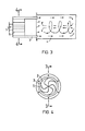
- the element for generating swirl can consist in a relative assignment of the inflow member (1) to the prechamber (2) by blowing the gases to be burned tangentially into the prechamber (see FIG. 1 and FIG. 2).
- baffles (5) provided in the prechamber for generating the swirl.
- the swirl generating elements (5) are in the form of deflection plates according to FIG. 7 in the combustion chamber itself. Because of the high temperature load to which these swirl generating elements provided in the combustion chamber are exposed, they preferably consist of ceramic material.
- the baffles can consist of flat or curved plates.
- FIGS. 1 and 2 An arrangement according to FIGS. 1 and 2 is preferably used, the swirl being generated by tangentially introducing the gases to be burned into the prechamber.
- the ring channel (3) has a width, i.e. a distance between the inner and outer ring channel jacket between 1 and 60 mm, preferably between 5 and 40 mm, particularly preferably between 10 and 25 mm.
- the length of the ring channel should be three to ten times, preferably four to six times its width in order to ensure sufficient calming of the gas flow.
- a larger length of the ring channel is generally not troublesome, but can even lead to a further calming of the gas flows, but the above-mentioned length-to-width ratios are generally sufficient.
- the ring channel can be formed by two cylindrical, concentric tubes according to FIG. 1 and FIG. 3. Because of the simplicity of the design, such a configuration of the ring channel by concentric pipes is preferred if the gases to be burned do not cause extreme fluctuations in quantity subject to. Fluctuations in the amount of exhaust gas to be burned by a factor of 3 to 10, depending on the gas composition, are generally burnt back-burned by a burner with an annular channel thus formed. A greater decrease in the amount of gases to be burned, which jeopardizes the maintenance of the re-ignition-safe minimum speed in the ring channel, can then be compensated for by adding ambient air to the gas to be burned.
- the annular duct surfaces are conical, widening towards the combustion chamber, e.g. 5, because here the cylindrical jacket of the combustion chamber (4) is flown at an angle by the gases to be burned emerging from the annular channel, so that the jacket surface of the combustion chamber contributes to increasing the swirl in the combustion chamber.
- the ring channel is designed so that the width of the ring channel decreases with increasing radius, so that the open cross-sectional area of the ring channel, i.e. the flow cross-section for the burning gas, not enlarged.
- An increase in the open cross-sectional area in the direction of flow would lead to a reduction in the flow speed, which would result in the risk of the speed falling below the minimum.
- a disproportionate reduction in the width of the ring channel with a reduction in the open cross-sectional area is generally not detrimental, since this merely brings about an acceleration of the gas flow in the ring channel.
- FIG. 9 An embodiment of such a device is shown in FIG. 9.
- the ring channel is formed by two parallel conical lateral surfaces (3a) and (3b). Since the width of the ring channel is retained over the length of the ring channel, the gas is accelerated when flowing through the ring channel due to the reduction in the open cross-sectional area.
- the lateral surface (3b) facing away from the combustion chamber can be displaced in the axial direction by actuating the screw (7).
- any other suitable propulsion devices can be provided for the annular duct surface (3b), such as hydraulic or pneumatic. It may be also provided that the annular channel lateral surface (3b) resiliently Z .B. is held on an air cushion, and the width of the ring channel regulates itself depending on the amount of gas to be burned and the gas pressure thus building up in the antechamber.
- FIG. 11 Such an embodiment of the ring channel is shown in FIG. 11. With this shape of the ring channel, the open cross-sectional area is constant over the length of the ring channel with any width of the ring channel.
- the swirl at the entry of the gases to be burned into the ring channel is preferably set so that the friction of the gas flow on the lateral surfaces in the vicinity of the exit of the gas flow from the ring channel is as low as possible. This is the case when the ring channel center line matches at least in the region of the exit of the gas flow from the ring channel with a section of the curve according to formula (I).
- FIG. 9 and FIG. 10 Further expedient refinements of the device according to the invention result from FIG. 9 and FIG. 10, to which reference is made below. It is expedient to provide cooling chambers (6) in the vicinity of the annular duct surface to ensure a sufficient size of the extinguishing distance, into which liquid or gaseous cooling medium is conveyed via supply lines (6a). Ambient air is preferably used as the cooling medium. To observe the flame in the combustion chamber, it may be advisable to provide a viewing window (9). In addition to the swirl generation by tangential introduction of the gases to be burned (1) into the antechamber (2), swirl plates (5) are provided in the device according to FIG bolts (12) are rotatably supported. This is particularly advantageous if the cheapest twist is to be determined experimentally in a prototype of the device according to the invention.
- the antechamber (2) is used for the uniform spreading of the gas to be burned, which is fed through the introducing member (1), for uniform application to the annular channel over its circumference. It may be expedient here to ensure a uniform application of the gas to the circumference of the ring channel via an annular slot (11) with an adjustable ring diaphragm as a throttle valve. '
- auxiliary units such as e.g. to provide an electrical ignition device, supply devices for additional fuel or additional air or supply lines for the injection of waste water loaded with heat-decomposable contaminants and / or for the pneumatic introduction of finely divided heat-decomposable solid substances.
Landscapes
- Engineering & Computer Science (AREA)
- Chemical & Material Sciences (AREA)
- Environmental & Geological Engineering (AREA)
- Chemical Kinetics & Catalysis (AREA)
- Mechanical Engineering (AREA)
- General Engineering & Computer Science (AREA)
- Health & Medical Sciences (AREA)
- General Chemical & Material Sciences (AREA)
- Analytical Chemistry (AREA)
- Oil, Petroleum & Natural Gas (AREA)
- Biomedical Technology (AREA)
- Toxicology (AREA)
- Combustion & Propulsion (AREA)
- Incineration Of Waste (AREA)
- Gas Burners (AREA)
- Pre-Mixing And Non-Premixing Gas Burner (AREA)
Applications Claiming Priority (2)
| Application Number | Priority Date | Filing Date | Title |
|---|---|---|---|
| DE19772745493 DE2745493A1 (de) | 1977-10-10 | 1977-10-10 | Verfahren und vorrichtung zur verbrennung explosibler gase |
| DE2745493 | 1977-10-10 |
Publications (1)
| Publication Number | Publication Date |
|---|---|
| EP0001438A1 true EP0001438A1 (fr) | 1979-04-18 |
Family
ID=6021089
Family Applications (1)
| Application Number | Title | Priority Date | Filing Date |
|---|---|---|---|
| EP78101029A Withdrawn EP0001438A1 (fr) | 1977-10-10 | 1978-09-29 | Procédé et appareil pour brûler des gaz explosifs |
Country Status (8)
| Country | Link |
|---|---|
| EP (1) | EP0001438A1 (fr) |
| JP (1) | JPS5462536A (fr) |
| BE (1) | BE28T1 (fr) |
| DE (2) | DE2745493A1 (fr) |
| FR (1) | FR2424480A1 (fr) |
| GB (1) | GB2041504B (fr) |
| IT (1) | IT7851398A0 (fr) |
| NL (1) | NL7815022A (fr) |
Cited By (2)
| Publication number | Priority date | Publication date | Assignee | Title |
|---|---|---|---|---|
| EP0021321A3 (fr) * | 1979-06-27 | 1981-04-15 | Bayer Ag | Brûleur à flamme tourbillonnante |
| WO2010097197A3 (fr) * | 2009-02-24 | 2011-10-27 | Eisenmann Ag | Brûleur pour dispositif de postcombustion thermique |
Families Citing this family (5)
| Publication number | Priority date | Publication date | Assignee | Title |
|---|---|---|---|---|
| GB2199929B (en) * | 1987-01-17 | 1990-12-05 | Mcintyre J | Afterburners |
| US5321327A (en) * | 1992-01-30 | 1994-06-14 | 21St Century Power & Light Corporation | Electric generator with plasma ball |
| US5593301A (en) * | 1993-07-09 | 1997-01-14 | Alliant Techsystems, Inc. | Apparatus and method for burning energetic material |
| US5861600A (en) * | 1996-08-21 | 1999-01-19 | Jensen; Donald C. | Fuel plasma vortex combustion system |
| JP2025145797A (ja) * | 2024-03-22 | 2025-10-03 | 日本軽金属株式会社 | 脱臭制御システム及び脱臭制御方法 |
Citations (7)
| Publication number | Priority date | Publication date | Assignee | Title |
|---|---|---|---|---|
| DE232500C (fr) * | ||||
| US2581075A (en) * | 1948-05-26 | 1952-01-01 | Affiliated Gas Equipment Inc | Gas burner including combustion tunnel |
| FR1409309A (fr) * | 1964-05-29 | 1965-08-27 | Thermanu | Brûleur à gaz |
| DE2317513A1 (de) * | 1973-04-07 | 1974-10-24 | Boehler Zenkner Stroemtech | Verfahren zum betreiben einer brenneranordnung fuer anlagen zum thermischen nachverbrennen von abluft aus industriellen arbeitsanlagen und mit einem solchen verfahren zu betreibende brenneranordnung |
| DE2434960A1 (de) * | 1973-07-19 | 1975-02-06 | Participations Ind C E P I Com | Gasbrenner |
| GB1465310A (en) * | 1973-11-19 | 1977-02-23 | Nils Oestbo Ab | Furnace for destructing obnoxious products contained in a gaseous fluid |
| FR2366517A1 (fr) * | 1976-09-29 | 1978-04-28 | Kleinewefers Ind Co Gmbh | Procede et appareil pour l'epuration des effluents gazeux |
-
1977
- 1977-10-10 DE DE19772745493 patent/DE2745493A1/de not_active Withdrawn
-
1978
- 1978-07-29 NL NL7815022A patent/NL7815022A/xx unknown
- 1978-09-29 DE DE19782857182 patent/DE2857182A1/de not_active Withdrawn
- 1978-09-29 GB GB7928001A patent/GB2041504B/en not_active Expired
- 1978-09-29 EP EP78101029A patent/EP0001438A1/fr not_active Withdrawn
- 1978-09-29 BE BEBTR28A patent/BE28T1/fr not_active IP Right Cessation
- 1978-10-06 JP JP12275778A patent/JPS5462536A/ja active Pending
- 1978-10-06 IT IT7851398A patent/IT7851398A0/it unknown
-
1979
- 1979-06-01 FR FR7914394A patent/FR2424480A1/fr not_active Withdrawn
Patent Citations (7)
| Publication number | Priority date | Publication date | Assignee | Title |
|---|---|---|---|---|
| DE232500C (fr) * | ||||
| US2581075A (en) * | 1948-05-26 | 1952-01-01 | Affiliated Gas Equipment Inc | Gas burner including combustion tunnel |
| FR1409309A (fr) * | 1964-05-29 | 1965-08-27 | Thermanu | Brûleur à gaz |
| DE2317513A1 (de) * | 1973-04-07 | 1974-10-24 | Boehler Zenkner Stroemtech | Verfahren zum betreiben einer brenneranordnung fuer anlagen zum thermischen nachverbrennen von abluft aus industriellen arbeitsanlagen und mit einem solchen verfahren zu betreibende brenneranordnung |
| DE2434960A1 (de) * | 1973-07-19 | 1975-02-06 | Participations Ind C E P I Com | Gasbrenner |
| GB1465310A (en) * | 1973-11-19 | 1977-02-23 | Nils Oestbo Ab | Furnace for destructing obnoxious products contained in a gaseous fluid |
| FR2366517A1 (fr) * | 1976-09-29 | 1978-04-28 | Kleinewefers Ind Co Gmbh | Procede et appareil pour l'epuration des effluents gazeux |
Cited By (3)
| Publication number | Priority date | Publication date | Assignee | Title |
|---|---|---|---|---|
| EP0021321A3 (fr) * | 1979-06-27 | 1981-04-15 | Bayer Ag | Brûleur à flamme tourbillonnante |
| WO2010097197A3 (fr) * | 2009-02-24 | 2011-10-27 | Eisenmann Ag | Brûleur pour dispositif de postcombustion thermique |
| US9194580B2 (en) | 2009-02-24 | 2015-11-24 | Eisenmann Ag | Burner for a thermal post-combustion device |
Also Published As
| Publication number | Publication date |
|---|---|
| NL7815022A (fr) | 1979-08-31 |
| DE2857182A1 (de) | 1980-07-10 |
| GB2041504B (en) | 1982-11-17 |
| IT7851398A0 (it) | 1978-10-06 |
| JPS5462536A (en) | 1979-05-19 |
| GB2041504A (en) | 1980-09-10 |
| DE2745493A1 (de) | 1979-04-19 |
| BE28T1 (fr) | 1979-12-07 |
| FR2424480A1 (fr) | 1979-11-23 |
Similar Documents
| Publication | Publication Date | Title |
|---|---|---|
| DE68915613T2 (de) | Sauerstoffstrahlbrenner und Verbrennungsverfahren. | |
| DE69101794T2 (de) | Brennkammer und Verbrennungsverfahren. | |
| DE69017318T2 (de) | Verbrennungsverfahren mit verbesserter Temperaturverteilung. | |
| DE2415036C2 (de) | Brennkammer für Gasturbinentriebwerke mit Regenerativ-Wärmetauschern | |
| DE69514672T2 (de) | Brenner mit sehr niedrigem nox-ausstoss | |
| DE2461078C2 (de) | Verfahren zur Verringerung des Gehalts an Stickstoffoxiden, Kohlenmonoxid und Kohlenstoff in einem Abgas, sowie Feuerungsanlage zur Durchführung des Verfahrens | |
| DE69215705T2 (de) | Verbrennung mit kohärentem Strahl | |
| DE3852651T2 (de) | Vorrichtung und verfahren zur herstellung einer hochlichtgebenden flamme. | |
| DE69515109T2 (de) | Verfahren und Vorrichtung zum Verbrennen sauerstoffhaltiger Bestandteile in einem Prozessgas | |
| DE2841637A1 (de) | Brenneranlage zum verbrennen gasfoermiger oder fluessiger brennstoffe | |
| DE69225555T2 (de) | Verbrennungsverfahren mit Rückführung und Pfropfenströmung | |
| DE2901099A1 (de) | Kraftstoffverdampfungsvorrichtung, damit ausgeruestete brennkammer und verfahren zum betreiben derselben | |
| EP1212258A1 (fr) | Procede pour un bruleur et un dispositif correspondant | |
| DE2807853A1 (de) | Brenner fuer gasturbinen | |
| EP0289851A2 (fr) | Procédé et brûleur pour la combustion de combustible | |
| DE2745488C2 (de) | Verfahren und Vorrichtung zur Verbrennung explosibler Gase | |
| DE1592462C3 (de) | Vorrichtung zur Verbrennung von Titantetrachlorid | |
| DE2528559A1 (de) | Verfahren und vorrichtung zur durchfuehrung chemischer reaktionen zwischen fliessenden medien | |
| DE2643797A1 (de) | Verfahren und vorrichtung zum thermischen reinigen von abluft | |
| DE2745493A1 (de) | Verfahren und vorrichtung zur verbrennung explosibler gase | |
| DE69018059T2 (de) | Verfahren und vorrichtung zur verbrennung von giftigen sauerstofffreien abgasen. | |
| DE102015107360A1 (de) | Niedriges NOx -Verbrennungssystem für Wanderrostpelletierungsanlagen | |
| EP0396554A1 (fr) | Bruleur. | |
| DE6606067U (de) | Vorrichtung zum erzeugen eines flammstrahls | |
| EP2821700B1 (fr) | Lance de combustion ou de torchage de gaz d'échappement combustibles |
Legal Events
| Date | Code | Title | Description |
|---|---|---|---|
| PUAI | Public reference made under article 153(3) epc to a published international application that has entered the european phase |
Free format text: ORIGINAL CODE: 0009012 |
|
| 17P | Request for examination filed | ||
| AK | Designated contracting states |
Designated state(s): BE CH DE FR GB NL |
|
| STAA | Information on the status of an ep patent application or granted ep patent |
Free format text: STATUS: THE APPLICATION IS DEEMED TO BE WITHDRAWN |
|
| 18D | Application deemed to be withdrawn | ||
| 32 | Conversion | ||
| RIN1 | Information on inventor provided before grant (corrected) |
Inventor name: GOCKEL, CLAUS Inventor name: BOERGER, GOETZ-GERALD, DR. Inventor name: HUENING, WERNER Inventor name: FRANZKE, GERD-PETER |