EP0001496A1 - Verfahren und Vorrichtung zum Energietransport durch ein System der Wasserstoff-Hydridsorption und Anwendung des Systems auf Kälteerzeugungs- und Wärmepumpenkreisläufe - Google Patents
Verfahren und Vorrichtung zum Energietransport durch ein System der Wasserstoff-Hydridsorption und Anwendung des Systems auf Kälteerzeugungs- und Wärmepumpenkreisläufe Download PDFInfo
- Publication number
- EP0001496A1 EP0001496A1 EP78300438A EP78300438A EP0001496A1 EP 0001496 A1 EP0001496 A1 EP 0001496A1 EP 78300438 A EP78300438 A EP 78300438A EP 78300438 A EP78300438 A EP 78300438A EP 0001496 A1 EP0001496 A1 EP 0001496A1
- Authority
- EP
- European Patent Office
- Prior art keywords
- heat
- hydrogen
- reactors
- reactor
- materials
- Prior art date
- Legal status (The legal status is an assumption and is not a legal conclusion. Google has not performed a legal analysis and makes no representation as to the accuracy of the status listed.)
- Withdrawn
Links
Images


Classifications
-
- F—MECHANICAL ENGINEERING; LIGHTING; HEATING; WEAPONS; BLASTING
- F25—REFRIGERATION OR COOLING; COMBINED HEATING AND REFRIGERATION SYSTEMS; HEAT PUMP SYSTEMS; MANUFACTURE OR STORAGE OF ICE; LIQUEFACTION SOLIDIFICATION OF GASES
- F25B—REFRIGERATION MACHINES, PLANTS OR SYSTEMS; COMBINED HEATING AND REFRIGERATION SYSTEMS; HEAT PUMP SYSTEMS
- F25B17/00—Sorption machines, plants or systems, operating intermittently, e.g. absorption or adsorption type
- F25B17/12—Sorption machines, plants or systems, operating intermittently, e.g. absorption or adsorption type using desorption of hydrogen from a hydride
-
- C—CHEMISTRY; METALLURGY
- C09—DYES; PAINTS; POLISHES; NATURAL RESINS; ADHESIVES; COMPOSITIONS NOT OTHERWISE PROVIDED FOR; APPLICATIONS OF MATERIALS NOT OTHERWISE PROVIDED FOR
- C09K—MATERIALS FOR MISCELLANEOUS APPLICATIONS, NOT PROVIDED FOR ELSEWHERE
- C09K5/00—Heat-transfer, heat-exchange or heat-storage materials, e.g. refrigerants; Materials for the production of heat or cold by chemical reactions other than by combustion
- C09K5/02—Materials undergoing a change of physical state when used
- C09K5/04—Materials undergoing a change of physical state when used the change of state being from liquid to vapour or vice versa
- C09K5/047—Materials undergoing a change of physical state when used the change of state being from liquid to vapour or vice versa for absorption-type refrigeration systems
-
- Y—GENERAL TAGGING OF NEW TECHNOLOGICAL DEVELOPMENTS; GENERAL TAGGING OF CROSS-SECTIONAL TECHNOLOGIES SPANNING OVER SEVERAL SECTIONS OF THE IPC; TECHNICAL SUBJECTS COVERED BY FORMER USPC CROSS-REFERENCE ART COLLECTIONS [XRACs] AND DIGESTS
- Y02—TECHNOLOGIES OR APPLICATIONS FOR MITIGATION OR ADAPTATION AGAINST CLIMATE CHANGE
- Y02A—TECHNOLOGIES FOR ADAPTATION TO CLIMATE CHANGE
- Y02A30/00—Adapting or protecting infrastructure or their operation
- Y02A30/27—Relating to heating, ventilation or air conditioning [HVAC] technologies
-
- Y—GENERAL TAGGING OF NEW TECHNOLOGICAL DEVELOPMENTS; GENERAL TAGGING OF CROSS-SECTIONAL TECHNOLOGIES SPANNING OVER SEVERAL SECTIONS OF THE IPC; TECHNICAL SUBJECTS COVERED BY FORMER USPC CROSS-REFERENCE ART COLLECTIONS [XRACs] AND DIGESTS
- Y02—TECHNOLOGIES OR APPLICATIONS FOR MITIGATION OR ADAPTATION AGAINST CLIMATE CHANGE
- Y02P—CLIMATE CHANGE MITIGATION TECHNOLOGIES IN THE PRODUCTION OR PROCESSING OF GOODS
- Y02P20/00—Technologies relating to chemical industry
- Y02P20/10—Process efficiency
- Y02P20/129—Energy recovery, e.g. by cogeneration, H2recovery or pressure recovery turbines
Definitions
- This invention relates to hydrogen-hydride absorption systems, that is to say systems in which reversibly hydridable materials are alternately hydrided and dehydrided with exothermic absorption and endothermic desorption of hydrogen that is transferred between the materials, and to their use for the transfer of thermal energy between a heat source and a heat sink at different temperatures to produce a refrigeration or heat pump effect or both.
- the basic system of this kind comprises two different hydridable materials whose hydrides have different decomposition temperatures at a given working pressure enclosed in a hydrogen containing atmosphere.
- the use of this system as a heat pump is described in U.S. specification No. 4 044 819.
- the first hydride is decomposed by heating to a high temperature above its decomposition temperature with the release of hydrogen, which raises the pressure and is exothermically absorbed in and hydrides the second material that is maintained at a lower intermediate temperature below its decomposition temperature at the raised pressure, the heat released being extracted and delivered to a load or sink.
- the second hydride is then cooled, thus reducing the pressure, by exposure to a source of heat at a low temperature that is above its decomposition temperature at the lower pressure.
- the second hydride desorbs hydrogen with absorption of heat, and the hydrogen is exothermically absorbed in and hydrides the first material, with further evolution of heat to the intermediate temperature load.
- the cycle is repeated, the overall effect being the transfer of heat from both the low and high temperature sources to the intermediate temperature load.
- the efficiency of a system of this kind is increased by using a second parallel two-hydride system comprising the same second hydridable material and a third such material having a decomposition temperature between those of the first and second materials.
- the heat evolved in the exothermic hydriding of the first material is used to supply the energy required to dehydride the third material.
- the second material in each system withdraws heat for dehydriding from the low-temperature heat source and the second and third materials discharge the heat evolved during hydriding to the intermediate temperature heat load.
- This arrangement requires the use of two separate hydrogen flow systems and the transfer of heat between the two systems.
- the present invention provides a means of producing an efficient refrigeration or heat pump effect in a single hydrogen flow system.
- refrigeration and heating can be continuously and efficiently generated directly from the heats of hydrogen desorption and absorption, respectively, of the three or more hydridable material-hydride systems, which will be referred to hereinafter as hydride component systems.
- the improved refrigeration is achieved by cascading operation of three or more hydride component systems so as to decrease the hydrogen pressure in stages over a relatively narrow temperature differential between thermal source and thermal sink.
- Each cascading between hydride components requires a thermal source at a relatively low temperature and a heat output at a slightly higher temperature.
- the entire cycle is completed by raising the last hydride component system to a much higher temperature so that the equilibrium pressure is great enough to hydride the first hydride component system in the process of cascading between hydride components.
- the improved heat pump system works in reverse of the refrigeration system, that is by pressure staging between hydride component systems so as to increase the hydrogen pressure.
- the invention can also be used to improve the efficiency in heat engine cycles for the production of power by allowing them to operate with lower temperature thermal sinks.
- the use of the cascaded heat pump system with the thermally rejected energy of the heat engine cycle allows heat to be output at a higher temperature than the thermal sink, thus providing useful thermal source.
- the hydridable materials of the hydride component systems must all be different. These materials may be of the same alloy class, but the specific alloy compositions must be different in order that different equilibrium pressure-temperature relationships exist. Alloys which may be used in the systems include, but are not limited to, nickel-magnesium alloys, iron-titanium alloys, copper- magnesium alloys, vanadium-silicon alloys, lanthanum-nickel alloys, lanthanum-cobalt alloys, calcium-nickel alloys, and alloys of the generic formula RT 5 , where R is a rare earth and T is a 3d-transition metal.
- the characteristic response of hydridable materials to exposure to hydrogen gas under varying conditions of temperature and pressure namely the relationship of the equilibrium pressure to the equilibrium temperature over the phase transition from base material to hydrided base material, and the reverse reaction, is expressed by the empirical equation
- P e q is the equilibrium pressure of hydrogen in atmospheres
- T eq is the corresponding equilibrium temperature in degrees Kelvin
- A is a constant with dimensions of temperature
- B is a constant without dimensions.
- Tnis equation enables the preferred hydridable materials for use in the present invention to be determined. Such materials are those which will supply the necessary pressure differences over the desired operation temperatures of the refrigeration and heat pump modes of operation.
- the empirical equation is usually a best fit for the equilibrium data of absorption and desorption.
- Hysteresis is exhibited in that, for the same equilibrium temperature, the equilibrium pressure for absorption is sometimes higher than that for desorption.
- An inefficiency is also exhibited in that upon hydriding, the equilibrium pressure may increase for the same equilibrium temperature as the equilibrium hydride phase is approached. The reverse is also true in that, upon dehydriding the equilibrium pressure may decrease at the same equilibrium temperature of absorption as the equilibrium base material phase is approached.
- the constant A is related to the heat of absorption by being equal to the heat of formation divided by the universal gas constant.
- One advantageous combination of three hydridable materials comprises the alloy CaNi 5 , the alloy Ca 0.7 M 0.3 Ni 5 , where M stands for Mischmetal of rare earths, and the alloy Ca 0.4 M 0.6 Ni 5 .
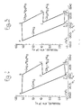
- the lines AF, DE and BC respectively represent the pressure-temperature equilibrium relationships for the CaNi 5 hydride, Ca 0.7 M 0.3 Ni 5 hydride, and the Ca 0.4 M 0.6 Ni 5 hydride.
- State A for the CaNi S hydride is at a temperature of 474°K (T 3 ) and 58 atmospheres (P 3 ).
- the CaNi 5 hydride is dehydrided at the temperature of 474°K and 58 atmospheres with a thermal input of 16,000 Joules/g H 2 .
- the hydrogen is absorbed on the Ca 0.4 M 0.6 Ni 5 alloy at state B, a pressure slightly below 58 atmospheres and a temperature of about 322° (T 1 ) which is maintained by removing the heat of absorption of about 11,300 Joules/g H 2 .
- State C is where the Ca 0.4 M 0.6 Ni 5 hydride is dehydrided at 10 atmospheres pressure (P 4 ) and a temperature of 273°K (T 2 ). The heat of desorption is about 11,300 Joules/g H 2 .
- the desorbed hydrogen is absorbed on the Ca 0.7 M 0.3 Ni 5 alloy at slightly lower pressure at State D. Thermal energy of 13,600 Joules/ g H 2 is released at about 322°K.
- the Ca 0.7 M 0.3 Ni 5 hydride is dehydrided at 273°K and 1.5 atmospheres (P 2 ) at State E.
- the heat of desorption is 13,600 Joules/g H 2 .
- the hydrogen is absorbed on the CaNi 5 alloy at slightly lower pressure (P 1 ) at State F. Thermal energy of 16,000 Joules/g H 2 is released at about 322°K.
- Figure 3 shows the heat pump mode being operated at the same temperature levels as the refrigeration mode.
- thermal energy of 16,000 Joules/g H 2 is supplied to the CaNi S hydride.
- Hydrogen is desorbed at a pressure of 1.5 atmospheres and absorbed on the Ca 0.7 M 0.3 Ni 5 alloy at State B.
- Thermal energy of 13,600 Joules/g H 2 is removed at slightly less than 273°K.
- the Ca 0.7 M 0.3 Ni 5 hydride is dehydrided at a pressure of 10 atmospheres as thermal energy of 13,600 Joules/G H 2 is supplied at 322°K.
- the desorbed hydrogen is absorbed on the Ca 0.4 M 0.6 Ni 5 alloy and thermal energy of 11,300 Joules/g H 2 at slightly less than 273°K is removed.
- the Ca 0.4 N 0.6 Ni 5 hydride is dehydrided by thermal energy of 11,30 0 Joules/g H 2 .
- the pressure is about 58 atmospheres and the temperature is about 322°K.
- the desorbed hydrogen is absorbed on the CaNi 5 alloy and thermal energy of 16,000 Joules/g H 2 is removed at a temperature slightly less than 474°K. This amount of thermal energy is the heat pump effect.
- the cycle Upon cooling the CaNi S hydride down to State A, the cycle is completed. In each hydrogen transfer stage absorption takes place at a slightly lower pressure than desorption.
- the Carnot efficiency of a heat engine cycle operating between 322°K and 273 0 K is 0.15.
- the Coefficient of Performance of a heat pump operated between 474 0 K and 322 0 K is 3.1.
- the maximum E.U.F. possible from a Carnot system would be 0.465.
- the ideal Energy Utilisation Factor of the CaNi 5 system is 84 percent of the Carnot limit.
- Figure 4 is a pressure-temperature diagram for a CaNi 5 based system in a refrigeration mode.
- This system operates between the temperaturesof 378° K and 300°K with heat rejection at 322°K.
- the energy rejected could be used as the heat input in the refrigeration mode at 300°K.
- heat would be rejected at 322°K.
- a heat pump cycle is actually a refrigeration cycle, the energy rejected of the refrigeration cycle has become useful, and the refrigeration load is the energy rejected in the power cycle.
- the energy rejected from the power cycle is considered as one unit of thermal energy which is used as the input to the refrigeration cycle, then 1.56 units of thermal energy are rejected at 322 0 K and the thermal input at 378°K is 0.56 units of thermal energy.
- the power cycle would operate at 20 percent efficiency and therefore would require 1.20 units of energy at 378°K.
- the total input of energy at 378°K would be 1.76 unit.
- an equivalent heat engine cycle is operated between a high temperature thermal source and a low temperature thermal sink by one hydride component. Refrigeration is then achieved by two or more other hydride component systems.
- the added hydride components allow pressure levels to remain relatively close between component systems when hydriding and dehydriding. A small pressure difference is necessary for hydriding and dehydriding, but a pressure difference much larger than necessary is wasteful.
- FIG. 5 of the drawings shows a system in which the principles of the invention are used for improving the efficiency of a power cycle by combining with the power cycle, a hydrogen absorption system according to the invention including three hydride components.
- a power cycle in which an energy conversion device is present for converting a portion of input thermal energy at temperature T1 to work, while rejecting the remainder of the thermal energy at temperature T 2 , a portion of this rejected thermal energy is utilised to dehydride a first hydride material, which first hydride material is in equilibrium at state A, as shown in Figure 5, at temperature T 2 and pressure P l .
- the thus desorbed hydrogen gas is absorbed by a second hydridable material at temperature T 3 , and at a pressure which is slightly less than P 1 .
- This state of the second hydridable material is state B on the pressure-temperature diagrams of Figure 5.
- the second hydride thus formed is cooled at constant volume to a temperature which is slightly less than T 2 at a pressure P 2 which is less than P1 (state C).
- the cooled second hydride, which has been cooled to state C is then heated by the use of another portion of the thermally rejected energy of the energy conversion device to desorb and supply hydrogen gas to a third hydridable material.
- a third hydride is thus formed which is saturated with hydrogen gas and is in equilibrium at a temperature of T 3 and a - pressure which is slightly lower than P 2 (as shown at state D in the pressure-temperature diagram).
- This third hydride material is heated, while retaining the volume thereof constant, to a temperature of T 1 and a pressure of P 3 , and in this manner is made to attain state E of the diagram.
- Continuing to heat the third hydride material at the temperature T 1 and a constant pressure of P 3 while releasing the volumetric restriction of confinement on this hydride, allows hydrogen gas to be desorbed from the third hydride, and the hydrogen gas thus desorbed can then be transferred to the first hydridable material to form the first hydride at a temperature T 3 and at a pressure slightly less than P 3 as signified by state F in Figure 5.
- the invention includes apparatus for carrying out the process, which comprises at least three reactors each containing a reversibly hydridable material having different absorption-desorption characteristics for hydrogen, valved conduits connecting the reactors in series in the order of their decomposition temperature at a given working pressure, and connecting the last and first reactor in the series to form a hydrogen flow circuit, means for supplying heat to each reactor, and means for removing heat from each reactor.
- apparatus for carrying out the process which comprises at least three reactors each containing a reversibly hydridable material having different absorption-desorption characteristics for hydrogen, valved conduits connecting the reactors in series in the order of their decomposition temperature at a given working pressure, and connecting the last and first reactor in the series to form a hydrogen flow circuit, means for supplying heat to each reactor, and means for removing heat from each reactor.
- a set of reactors (otherwise referred to as a reactor system) may be employed, as will be explained in more detail hereinafter.
- Each reactor in a given set
- each means for supplying heat to or removing it from the reactors is a valved loop connecting a heat exchanger with the reactor and including a circulatory pump for circulating hydrogen from the hydrogen circuit through the reactor and heat exchanger.
- the apparatus includes three identical hydride reactor systems 10; 110, 210 (sometimes hereinafter referred to as sub-systems), each containing a different hydriding material.
- Each system is made up of four reactors, those in system 10 being numbered 12, 14, 16, 18, and those in systems 110 and 210 being correspondingly numbered 112, etc, and 212, etc.
- Heat is removed from or supplied to reactors in systems 10, 110 and 210 by heat exchangers 20 and 22,120 and 122 and 220 and 222 respectively.
- These heat exchangers are advantageously holding tanks for a liquid which will not dissolve hydrogen.and whose vapour is inert to the material in the reactor.
- the hydrogen gas of the absorption systems is bubbled through the liquid in order to be cooled or heated and passes through the reactors in direct contact with the hydridable material. This makes possible a very high rate of heat transfer between the hydrogen gas and the liquid in the heat exchanger and between the hydrogen and the material in the reactor. Since the heat transfer is the rate limiting step for hydriding reactors where heat transfer is by conduction, heat transfer by direct flow over the large surface area of the hydriding alloy and through the liquid will substantially decrease cycling time.
- the refrigeration mode of operation will first be described. This requires a high temperature thermal input into hydride component system 10 from heat exchanger 20. Hydrogen gas at relatively high temperature is supplied through conduit 24 to circulator pump 26 which compresses it to a pressure above the equilibrium pressure of the hydridable material in system 10. The circulating hydrogen gas is charged to system 10 through manifold 28 and is admitted, in a sequence hereinafter described, to the reactors 12-18 through branch conduits 30, 32, 34 and 36 via valves 38, 40, 42 and 44, respectively. Reactors 12-18 are connected by branch return conduits 46, 48, 50 and 52, respectively, to return manifold 54.
- the heat of absorption is removed from system 10 by means of low pressure hydrogen gas circulating through heat exchanger 22.
- .Circulator pump 58 is supplied with hydrogen gas via conduit 56.
- System 10 is supplied.with the circulating hydrogen gas by means of manifold 60 and the hydrogen gas is admitted to reactors 12-18 through branch conduits 62, 64, 66 and 68, respectively, containing valves 70, 72, 74 and 76.
- Branch return conduits 78, 80, 82 and 84 are connected to return manifold 86.
- Hydride component reactor systems 110 and 210 consist of systems equivalent to hydride component system 10 with equivalent components identified by equivalent reference numbers in the 100 and 200 series.
- Systems 110 and 210 serve as the equivalent of the mechanical refrigeration system and therefore must have heat supplied as the heat of desorption at a relatively low temperature to each of the systems. Heats of absorption are removed at a relatively higher temperature from each of the systems 110 and 210.
- System 10 serves as the heat engine equivalent with the heat of absorption supplied at a relatively high temperature and with heat rejected at some lower temperature.
- the heat exchangers 120 and 220 serve to remove the heat of absorption of the hydrogen gas at a temperature intermediate to that of the high temperature input to system 10 and the low temperature refrigeration load, the refrigeration being achieved by supplying the heat of desorption to systems 110 and 210 at a relatively low temperature by heat exchangers 122 and 222 respectively.
- systems 110 and 210 serve as the equivalent to the heat engine cycle. Operating within a small temperature differential between thermal source and sink, the heat engine cycle is inefficient. Therefore pressure staging is used between systems 110 and 210 to increase the pressure so that system 10 may be hydrided at a relatively high temperature.
- System 10 is the equivalent of the mechanical refrigeration system and supplies the heat pump effect.
- Heat exchanger 122 serves to remove the heat of absorption from system 110 as does--heat exchanger 222 in system 210. Heat is supplied as the heat of desorption to system 110 by heat exchanger 120 and to system 210 by heat exchanger 220. The heat pump effect is achieved by removing the heat of absorption from heat exchanger 20 in system 10. Heat of desorption is supplied to system 10 by heat exchanger 22.
- Hydrogen is conveyed between reactors of systems 1C, 110 and 210 via manifolds 300, 318, :340 and 370.
- Reactors 12-18 of system 10 are connected to manifold 300 by conduits 302, 304, 306 and 308, respectively, and containing valves 310, 312, 314 and 316.
- Manifold 318 is connected to reactors 210-218 via conduits 320, 322, 324, and 326, respectively, containing valves 328, 330, 332, and 334, respectively.
- Reactor systems 110 and 210 are interconnected by manifold 340 which is connected to reactors 112 and 212 by conduit 342 which contains valves 350 and 358.
- Reactors 114 and 214 are connected by conduit 344 which contains valves 352 and 360.
- Reactors 116 and 216 are connected by conduit 346 which contains valves 354 and 362.
- the reactors 118 and 218 of system 110 and 210 are connected to manifold 340 by conduit 348 which contains valves 356 and 364.
- Reactor systems 10 and 110 are connected by manifold 370.
- Conduit 372 interconnects manifold 370 to reactors 12 and 112 and contains valves 380 and 388.
- Reactors 14 and 114 are connected to the manifold 370 by conduit 374 which contains valves 382 and 390.
- Reactors 16 and 116 are connected by conduit 376 which contains valves 384 and 392.
- the last two reactors of systems 10 and 110 are connected to manifold 370 by conduit 378 which contains valves 386 and 394.
- the hydridable material contained in the reactors of system 10 is assumed to be the alloy CaNi S .
- the reactors of system 110 are assumed to contain the alloy Ca 0.7 M 0.3 Ni 5 where M stands for Mischmetal of rare earths and the reactors in system 210 contain the alloy Ca 0.4 bi 0.6 Ni 5 .
- the reactor 12 in system 10 will be considered to be in a fully hydrided and activated state, i.e., a hydride of the alloy CaNi S has been formed and the temperature of the reactor has been heated to 474°K.
- Reactor 212 of system 210 is in a fully dehydrided and deactivated state, i.e. a hydride of the alloy Ca 0.4 M 0.6 Ni 5 has not formed, and the temperature of reactor 210 is 322°K.
- valve 310 is opened to permit hydrogen to flow to reactor 212 to commence hydriding.
- the hydrogen pressure supplied by reactor 12 is typically at a pressure of 58 atmospheres and a temperature of 474°K.
- To dehydride the CaNi 5 hydride requires 16,000 Joules/g H 2 of thermal energy.
- reactor 212 is hydriding by absorption of hydrogen gas from manifold 318 through open valve 328 in branch conduit 320.
- the reactor evolves heat of 11,300 Joules/g H 2 , which is removed by hydrogen gas circulating through heat exchanger 220.
- reactor 216 Concurrent to the operations of reactors 12 and 212, reactor 216 is dehydriding, circulating hydrogen gas from heat exchanger 222 supplying the heat of desorption of 11,300 Joules/g H 2 at a temperature of 273°K.
- the hydrogen pressure in reactor 216 is slightly higher than 10 atmospheres.
- the hydrogen gas released from reactor 216 is absorbed in the alloy in reactor 116.
- the evolved heat of reactor 116 is at a temperature of 322 0 K maintained by circulating hydrogen gas from heat exchanger 120.
- the heat of absorption of reactor 116 is 13,600 Joules/ g H 2 .
- reactor 112 is dehydriding and reactor 16 is hydriding. These two reactors improve energy utilisation over a circuit containing only two hydride components.
- Reactor 112 is dehydriding by supplying to it thermal energy of 13,600 Joules/g K 2 at 273 0 K.
- Reactor 16 is hydrided at 322 0 K and releases the heat of absorption of 16,000 Joules/g H 2 .
- the dehydriding occuring in reactor 112 is caused by circulating hydrogen gas from heat exchanger 122 at a temperature of 273 0 K.
- the hydrogen gas released upon desorption is discharged through open valve 388 to manifold 370 at a pressure of 1.5 atmospheres. Valves 138 and 350 are closed. Hydrogen from manifold 370 is admitted to reactor 16 through conduit 376 and open valve 384.
- the heat of absorption is removed by circulating hydrogen gas to reactor 16 from heat exchanger 22 at 322°K.
- the next phase for the reactors begins when reactors 12, 112 and 216 are fully dehydrided and their deactivation is commenced. Deactivation requires that the pressure in these reactors be adjusted so that these reactors can be hydrided in the next phase. Deactivation is effected by bringing the reactors to the hydriding temperature. This and the simultaneous activation step for reactors 16, 116, and 212 could be done as a heat recovery step by heat exchange between reactors 12 and 16, 112 and 116 and 212 and 216. Deactivation may also be considered, however, as a part of the hydriding step and activation as part of the dehydriding step.
- This next phase is a hydriding phase for reactors 12, 112, and 216 and a dehydriding phase for reactors 16, 116 and 212. Looking at reactors 16 and 216 first, reactor 16 dehydrides into reactor 216. The states of the hydrogen gas leaving reactor 16 are the same as when reactor 12 was dehydriding, described above.
- Valve 314 is opened to manifold 300 and desorbed hydrogen gas is charged to reactor 216 through manifold 318 and the open valve 332 contained in conduit 324. The heat of absorption in reactor 216 is removed by heat exchanger 220.
- reactor 212 dehydrides, hydrogen gas therefrom at a pressure of 10 atmospheres is charged to reactor 112. Thermal energy at 273°K is supplied by heat exchanger 222. The heat of absorption at 322 0 K of reactor 112 is removed by the circulating hydrogen gas from heat exchanger 120.
- reactor 116 dehyrides hydrogen gas therefrom is charged to reactor 12.
- Thermal energy at 273°K is supplied to reactor 116 from heat exchanger 122.
- the heat of absorption of reactor 12 is removed through heat exchanger 22.
- the final phase for reactors 12, 112, and 216 is the activation phase and for reactors 16, 116 and 212 is the deactivation phase.
- the activation phase may again be considered part of the dehydriding phase, which is the next phase in a new cycle for reactors 12, 112, and 216.
- the deactivation phase may be considered as part of the hydriding phase for reactors 16, 116 and 212.
- the hydriding phase is the next phase in a new cycle for reactors 16, 116, and 212.
- Table II shows the status of the various valves used in controlling flows of the hydrogen gases between heat exchangers and reactors.
- Heat exchangers 122 and 222 provide refrigeration sinks of 24,900 Joules/g H 2 at 273 0 K.
- Heat exchangers 22, 120, and 220 provide thermal energy of 40,900 Joules/g H 2 at 322°K.
- Thermal energy of 16,000 Joules/g H 2 must be supplied at 474°K to heat exchanger 20.
- the ideal E.U. F . (Energy Utilisation Factor) for these systems is 4.1.
- the maximum efficiency of a refrigeration absorption cycle operating at the described temperature is, by the Carnot analogy, 1.79.
- the ideal limit for the CaNi S alloy systems is 24,900 Joules/16,000 1.55 or 86 percent of the Carnot limit.
Landscapes
- Engineering & Computer Science (AREA)
- Chemical & Material Sciences (AREA)
- Physics & Mathematics (AREA)
- Thermal Sciences (AREA)
- Chemical Kinetics & Catalysis (AREA)
- General Engineering & Computer Science (AREA)
- Mechanical Engineering (AREA)
- Combustion & Propulsion (AREA)
- Materials Engineering (AREA)
- Organic Chemistry (AREA)
- Sorption Type Refrigeration Machines (AREA)
- Physical Or Chemical Processes And Apparatus (AREA)
- Hydrogen, Water And Hydrids (AREA)
Applications Claiming Priority (2)
| Application Number | Priority Date | Filing Date | Title |
|---|---|---|---|
| US83810677A | 1977-09-30 | 1977-09-30 | |
| US838106 | 1977-09-30 |
Publications (1)
| Publication Number | Publication Date |
|---|---|
| EP0001496A1 true EP0001496A1 (de) | 1979-04-18 |
Family
ID=25276276
Family Applications (1)
| Application Number | Title | Priority Date | Filing Date |
|---|---|---|---|
| EP78300438A Withdrawn EP0001496A1 (de) | 1977-09-30 | 1978-09-29 | Verfahren und Vorrichtung zum Energietransport durch ein System der Wasserstoff-Hydridsorption und Anwendung des Systems auf Kälteerzeugungs- und Wärmepumpenkreisläufe |
Country Status (6)
| Country | Link |
|---|---|
| EP (1) | EP0001496A1 (de) |
| JP (1) | JPS5499095A (de) |
| CA (1) | CA1127857A (de) |
| ES (1) | ES473799A1 (de) |
| IT (1) | IT7851326A0 (de) |
| ZA (1) | ZA785532B (de) |
Cited By (3)
| Publication number | Priority date | Publication date | Assignee | Title |
|---|---|---|---|---|
| EP0055855A3 (de) * | 1980-12-29 | 1982-12-08 | Sekisui Kagaku Kogyo Kabushiki Kaisha | Metallhydridwärmepumpe |
| FR2620048A1 (fr) * | 1987-09-07 | 1989-03-10 | Elf Aquitaine | Procede de conduite d'une reaction thermochimique et installation permettant la mise en oeuvre de ce procede |
| EP0388132A1 (de) * | 1989-03-13 | 1990-09-19 | Sanyo Electric Co., Ltd | Thermisches Nutzbarmachungssystem, bei dem Wasserstoff absorbierende Legierungen verwendet werden |
Citations (2)
| Publication number | Priority date | Publication date | Assignee | Title |
|---|---|---|---|---|
| US4055962A (en) * | 1976-08-18 | 1977-11-01 | Terry Lynn E | Hydrogen-hydride absorption systems and methods for refrigeration and heat pump cycles |
| DE2749565A1 (de) * | 1976-11-08 | 1978-05-18 | Inco Europ Ltd | Nickel-calzium-speicher-legierung |
-
1978
- 1978-09-21 CA CA311,807A patent/CA1127857A/en not_active Expired
- 1978-09-29 ES ES473799A patent/ES473799A1/es not_active Expired
- 1978-09-29 ZA ZA00785532A patent/ZA785532B/xx unknown
- 1978-09-29 EP EP78300438A patent/EP0001496A1/de not_active Withdrawn
- 1978-09-30 JP JP12112778A patent/JPS5499095A/ja active Pending
- 1978-10-02 IT IT7851326A patent/IT7851326A0/it unknown
Patent Citations (2)
| Publication number | Priority date | Publication date | Assignee | Title |
|---|---|---|---|---|
| US4055962A (en) * | 1976-08-18 | 1977-11-01 | Terry Lynn E | Hydrogen-hydride absorption systems and methods for refrigeration and heat pump cycles |
| DE2749565A1 (de) * | 1976-11-08 | 1978-05-18 | Inco Europ Ltd | Nickel-calzium-speicher-legierung |
Cited By (6)
| Publication number | Priority date | Publication date | Assignee | Title |
|---|---|---|---|---|
| EP0055855A3 (de) * | 1980-12-29 | 1982-12-08 | Sekisui Kagaku Kogyo Kabushiki Kaisha | Metallhydridwärmepumpe |
| EP0168062A3 (en) * | 1980-12-29 | 1986-04-16 | Sekisui Kagaku Kogyo Kabushiki Kaisha | Method for operating a metal hydride heat pump assembly |
| FR2620048A1 (fr) * | 1987-09-07 | 1989-03-10 | Elf Aquitaine | Procede de conduite d'une reaction thermochimique et installation permettant la mise en oeuvre de ce procede |
| EP0307297A1 (de) * | 1987-09-07 | 1989-03-15 | Societe Nationale Elf Aquitaine | Verfahren zur Durchführung einer thermochemischen Reaktion und Vorrichtung zur Durchführung dieses Verfahrens |
| US5056591A (en) * | 1987-09-07 | 1991-10-15 | Societe Nationale Elf Aquitaine | Method and apparatus for conducting a thermochemical absorption and desorption reaction between a gas and a solid |
| EP0388132A1 (de) * | 1989-03-13 | 1990-09-19 | Sanyo Electric Co., Ltd | Thermisches Nutzbarmachungssystem, bei dem Wasserstoff absorbierende Legierungen verwendet werden |
Also Published As
| Publication number | Publication date |
|---|---|
| CA1127857A (en) | 1982-07-20 |
| IT7851326A0 (it) | 1978-10-02 |
| JPS5499095A (en) | 1979-08-04 |
| ES473799A1 (es) | 1979-04-01 |
| ZA785532B (en) | 1979-09-26 |
Similar Documents
| Publication | Publication Date | Title |
|---|---|---|
| US4055962A (en) | Hydrogen-hydride absorption systems and methods for refrigeration and heat pump cycles | |
| US3943719A (en) | Hydride-dehydride power system and methods | |
| US4044819A (en) | Hydride heat pump | |
| US4198827A (en) | Power cycles based upon cyclical hydriding and dehydriding of a material | |
| EP0007143A1 (de) | Vorrichtung und Verfahren zum zyklischen Transport eines Materials in einem Hydrid/Dehydrid-System | |
| US4188795A (en) | Hydrogen-hydride absorption systems and methods for refrigeration and heat pump cycles | |
| US4262739A (en) | System for thermal energy storage, space heating and cooling and power conversion | |
| Babu et al. | Thermodynamic analysis of compressor operated resorption thermochemical energy storage system for heat storage, combined cooling and heat upgradation | |
| EP2391846A1 (de) | Kontinuierlich betreibbarer metallhydridwasserstoffkompressor sowie betriebsverfahren dafür | |
| Choudhari et al. | Thermodynamic simulation of hydrogen based thermochemical energy storage system | |
| US4090361A (en) | Power cycles based upon cyclical hydriding and dehydriding of a material | |
| CN114033505A (zh) | 一种热电联供型分布式压缩空气系统及其控制方法 | |
| EP0001496A1 (de) | Verfahren und Vorrichtung zum Energietransport durch ein System der Wasserstoff-Hydridsorption und Anwendung des Systems auf Kälteerzeugungs- und Wärmepumpenkreisläufe | |
| Mohan et al. | Studies on thermodynamic performance of three stage sorption heat transformer | |
| Meng et al. | Study of integrated metal hydrides heat pump and cascade utilization of liquefied natural gas cold energy recovery system | |
| Nagel et al. | Dynamic behaviour of paired metal hydrides: I. Experimental method and results | |
| US5174367A (en) | Thermal utilization system using hydrogen absorbing alloys | |
| Popeneciu et al. | Investigation on a three-stage hydrogen thermal compressor based on metal hydrides | |
| USRE30840E (en) | Hydrogen-hydride absorption systems and methods for refrigeration and heat pump cycles | |
| Vasil’ev et al. | Multisalt-carbon chemical cooler for space applications | |
| Gambini | Metal hydride energy systems performance evaluation. Part B: performance analysis model of dual metal hydride energy systems | |
| Satheesh et al. | Simulation of double-stage double-effect metal hydride heat pump | |
| US11440796B2 (en) | Metal hydride compressor control device and method | |
| US6298665B1 (en) | Power generating device employing hydrogen absorbing alloys and low heat | |
| JP2568484B2 (ja) | 多重効用ヒ−トポンプ装置 |
Legal Events
| Date | Code | Title | Description |
|---|---|---|---|
| PUAI | Public reference made under article 153(3) epc to a published international application that has entered the european phase |
Free format text: ORIGINAL CODE: 0009012 |
|
| AK | Designated contracting states |
Designated state(s): BE CH DE FR GB NL SE |
|
| STAA | Information on the status of an ep patent application or granted ep patent |
Free format text: STATUS: THE APPLICATION IS DEEMED TO BE WITHDRAWN |
|
| 18D | Application deemed to be withdrawn |