EP0001532A1 - Ultraschallvorrichtung zum Sichtbarmachen eines dünnen Schnittes aus einem Körper - Google Patents
Ultraschallvorrichtung zum Sichtbarmachen eines dünnen Schnittes aus einem Körper Download PDFInfo
- Publication number
- EP0001532A1 EP0001532A1 EP78400126A EP78400126A EP0001532A1 EP 0001532 A1 EP0001532 A1 EP 0001532A1 EP 78400126 A EP78400126 A EP 78400126A EP 78400126 A EP78400126 A EP 78400126A EP 0001532 A1 EP0001532 A1 EP 0001532A1
- Authority
- EP
- European Patent Office
- Prior art keywords
- transducers
- row
- ultrasonic
- ultrasound
- probe
- Prior art date
- Legal status (The legal status is an assumption and is not a legal conclusion. Google has not performed a legal analysis and makes no representation as to the accuracy of the status listed.)
- Granted
Links
- 238000012800 visualization Methods 0.000 title description 9
- 239000000523 sample Substances 0.000 claims abstract description 36
- 238000002604 ultrasonography Methods 0.000 claims abstract description 29
- 239000000758 substrate Substances 0.000 claims description 13
- 210000001520 comb Anatomy 0.000 claims description 8
- 230000005855 radiation Effects 0.000 claims description 8
- 230000005540 biological transmission Effects 0.000 claims description 7
- 230000001934 delay Effects 0.000 claims description 4
- 230000000644 propagated effect Effects 0.000 claims description 3
- 230000002441 reversible effect Effects 0.000 claims description 3
- 230000004048 modification Effects 0.000 claims 1
- 238000012986 modification Methods 0.000 claims 1
- 230000001066 destructive effect Effects 0.000 abstract 1
- 239000003814 drug Substances 0.000 abstract 1
- 238000004519 manufacturing process Methods 0.000 abstract 1
- 230000010363 phase shift Effects 0.000 description 8
- 230000003287 optical effect Effects 0.000 description 7
- 230000015572 biosynthetic process Effects 0.000 description 4
- 238000010586 diagram Methods 0.000 description 3
- 238000000034 method Methods 0.000 description 3
- 210000000056 organ Anatomy 0.000 description 3
- 210000001519 tissue Anatomy 0.000 description 3
- 230000001427 coherent effect Effects 0.000 description 2
- 230000010355 oscillation Effects 0.000 description 2
- 230000001360 synchronised effect Effects 0.000 description 2
- 241000286209 Phasianidae Species 0.000 description 1
- 239000000919 ceramic Substances 0.000 description 1
- 239000003795 chemical substances by application Substances 0.000 description 1
- 230000003111 delayed effect Effects 0.000 description 1
- 238000001514 detection method Methods 0.000 description 1
- 238000006073 displacement reaction Methods 0.000 description 1
- 230000000694 effects Effects 0.000 description 1
- 210000002615 epidermis Anatomy 0.000 description 1
- 238000011156 evaluation Methods 0.000 description 1
- 230000005284 excitation Effects 0.000 description 1
- 239000007788 liquid Substances 0.000 description 1
- GQYHUHYESMUTHG-UHFFFAOYSA-N lithium niobate Chemical compound [Li+].[O-][Nb](=O)=O GQYHUHYESMUTHG-UHFFFAOYSA-N 0.000 description 1
- 238000011144 upstream manufacturing Methods 0.000 description 1
Images



Classifications
-
- G—PHYSICS
- G01—MEASURING; TESTING
- G01S—RADIO DIRECTION-FINDING; RADIO NAVIGATION; DETERMINING DISTANCE OR VELOCITY BY USE OF RADIO WAVES; LOCATING OR PRESENCE-DETECTING BY USE OF THE REFLECTION OR RERADIATION OF RADIO WAVES; ANALOGOUS ARRANGEMENTS USING OTHER WAVES
- G01S15/00—Systems using the reflection or reradiation of acoustic waves, e.g. sonar systems
- G01S15/88—Sonar systems specially adapted for specific applications
- G01S15/89—Sonar systems specially adapted for specific applications for mapping or imaging
- G01S15/8906—Short-range imaging systems; Acoustic microscope systems using pulse-echo techniques
- G01S15/8965—Short-range imaging systems; Acoustic microscope systems using pulse-echo techniques using acousto-optical or acousto-electronic conversion techniques
Definitions
- the present invention relates to ultrasound visualization systems which make it possible to form the image of a thin section of a body.
- This technique is based on the directivity of the ultrasonic wave beams, on the reflections undergone at each change in the acoustic impedance of the propagation medium and on the evaluation of the transmission delays, which makes it possible to locate the reflective zones with precision.
- a visible image can be formed by using a coherent beam of light passing through an ultrasound tank in which the body to be examined has been immersed.
- This technique was perfected by using a multi-element exploratory probe which avoids having to immerse the body to be examined in a tank.
- the principle of reconstruction of a visible image by diffraction is a delicate implementation, because it is necessary to provide a coherent light source associated with an optoacoustic cell connected to the probe and optical means for analyzing the reconstructed image allowing the visualization reading on the television screen of a slice of the body to be examined.
- the invention proposes to associate with the exploratory probe a bar of surface wave transducers arranged on a substrate so as to constitute a lens capable of forming the ultrasonic image: section explored by the probe.
- the ultrasound image thus produced is analyzed by a network of surface wave transducers, the output signals of which are connected to the television monitor which provides the image of the section.
- the optical means of image reconstruction by Bragg diffraction and the means of analysis of the reconstructed image are replaced by an elastic surface wave device which is much less expensive and bulky.
- the reversible operation of this device also makes it possible to use the explorer probe either as an ultrasound receiver or as a transmitter allowing exploration by angular scanning with a choice of several focusing lines.
- the subject of the invention is a system for ultrasound visualization of a thin section of a body, the system comprising an ultrasonic generator, an exploratory probe and visualization means, characterized in that it comprises an ultrasonic frequency-change lens composed of a first row of N volume wave electromechanical transducers forming the exploratory probe, of a set of N frequency-changing electrical circuits connected to a common local oscillator and of a second row N electromechanical surface wave transducers arranged on a substrate; the first and second rows having their homologous transducers interconnected two by two by the electric frequency changer circuits so as to constitute a transmission beam with N channels in which N signals circulate electric; the frequency of these volume waves being equal to the difference between the frequency of the surface waves and that of the signal produced by the local oscillator; the surface of the substrate carrying the second row of N transducers being provided with at least a third row of electromechanical surface wave transducers which, imaged by the ultrasonic lens, performs the discrete exploration of the section by focusing the ultrasonic energy exchanged
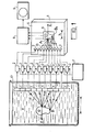
- FIG. 1 we can see the main elements of an ultrasound display system according to the invention.
- This system includes a multi-element explorer scnde composed of a row of electromechanical transducers with volume waves 1.
- the probe 1 is shown in a tank 10 which contains a liquid 11 in which the body 12 is immersed, the section of which is to be viewed.
- the body 12 would be an organ to be examined and the medium 11 would consist of the tissues surrounding the organ 12; the probe 1 would simply be applied against the patient's epidermis in order to collect, via the permeable tissues 11, the ultrasound radiation coming from the organ 12.
- the ultrasound emitter used for insonify the body.
- the insonification can be carried out by pheasant emitting by the probe 1 an ultrasonic pulse of frequency F 1 .
- the ultrasonic radiation emitted is confined in a lamellar beam oriented parallel to the plane of FIG. 1.
- the points 1, B of the body 12 continuously emit ultrasound of wavelength X.
- These ultrasound comes out materialized by rays d which reach the transducers 1 of the probe.
- Figure 1 there is shown a straight row of N transducers 1 and the axis X is the normal passing through the middle of the row of transducers.
- the N transducers 1 are connected by a set of N frequency change circuits 2.
- a local oscillator 7 operating at frequency F is connected to each frequency changer circuit 2.
- the circuits 2 deliver ultrasonic electrical signals at a frequency F corresponding to the difference between the frequencies F and F 1 ; these signals changed frequency are applied to a row of N electromechanical surface wave transducers which are arranged on the surface 5 of a substrate 4.
- the frequencies F and F 2 are advantageously greater than the frequency F 1 of the waves picked up by the exploratory probe 1 and taking into account the respective propagation speeds in the medium 11 and at the surface 5, it can be seen that the wavelength ⁇ 1 of the surface waves is less than ⁇ .
- row 3 has a homothetic configuration to that of row 1 with the homothetic ratio .
- This hypothesis is not limiting as will be seen below. Knowing that only the lower beat is transmitted, that is to say that the frequency of the local oscillator 7 is equal to the sum of the frequencies F 1 and F 2 , it is conceivable that a phase shift ⁇ existing between the signals delivered by two of the transducers 1 is changed sign when taking into account the two changed frequency signals which are applied to the two homologous transducers 3.
- point A of the object as point transmitter of ultra- sounds, the rays which lead to the transducers 1 are of unequal lengths. This results in phase shifts ⁇ between the signals delivered by the transducers 1.
- the ultrasound image 13 is picked up by a set 6 of receiver transducers, the detailed configuration of which will be given later.
- the electrical signals delivered by the detection assembly 6 are applied to a display device 9 of the television receiver type.
- a transmission circuit 8 ensures the routing of the detected signals and the distribution over time.
- the normal X 1 passing through the middle of row 3 is the image of the X axis.
- FIGS. 2 to 4 make it possible to better understand the similarities and the differences which exist between the ultrasonic lens which has just been described and a conventional optical lens.
- FIG. 2 shows an optical lens 14 cut in a transparent refractive medium.
- This converging lens optical axis 15 I-shaped image of the object 0 and I 1 the image of the object 0 1: It is noted that more the object is closer to the lens, the image moves away from it.
- FIG. 3 shows an ultrasonic lens with frequency change.
- the propagation medium m are propagated volume waves collected by the multi-element probe 1.
- a set of transmission channels 2 with frequency change produces a change in the sign of the phase of the signals applied to the row of transducers 3.
- the row of transducers 3 radiates elastic surface waves in the medium m 1 .
- the object 0 is imaged in I because, from point M, rays d 1 to d N leave which are focused in the form of rays D 1 to D N crossing at point M1.
- isochronous radiations emitted from point M are found isochronous in M 1 thanks to the change of sign of the phase
- an object 0 1 placed closer to the ballast probe is imaged in I 1 also closer to the row 3.
- the example of FIG. 3 is that of an operation with a unit magnification. In this case, the wavelengths are the same in the mediums m and m 1 .
- the ultrasonic lens of Figure 3 is capable of operating in both directions.
- the surface wave transducers 3 can receive a surface wave from point M 1 and the probe 1 then emits a beam of volume waves which converges at M.
- the frequency changer circuits must work in reverse.
- the ultrasonic lens has a difference with respect to the optical lens which is due to the directivity of the elementary transducers constituting the rows 1 and 3.
- a transducer 1 of axis 17 and height H can only collect ultrasonic waves inside the contour 16.
- the cylindrical part of this contour has a length L equal to and the conical part has an opening angle e equal to .
- all the transducers 1 do not necessarily cooperate in the formation of the image of a certain object point.
- FIG. 7 we can see an ultrasonic lens similar to that of FIG. 3.
- the ultrasonic energy coming from the point M is in the form of a pulse C of duration T.
- the energy re-radiated by row 3 is formed by pulses offset by A t. In the hatched range, this time offset ⁇ t does not exceed the duration T so that the transducers 1 and 3 which cover the hatched range ccoperate when focusing the ultrasonic energy coming from the point M.
- the other available transducers are put to contribution when focusing energy from points located outside the X axis.
- the configurations of rows 1 and 3 may differ from each other.
- the exploratory probe 1 is constituted for example by a straight row of transducers, but the row 3 instead of being straight is curved. If row 3 was straight the image of point M would form in M 2 . However, the curvature of row 3 causes a displacement of the image which effectively forms at point M 1 . It can be seen that the curving of the rows makes it possible to interest a greater number of transducers in focusing in cases where the directivity of the transducers or the duration of the pulses can limit this number.
- FIG. 6 an advantageous embodiment of the row of surface wave transducers can be seen. It is a piezoelectric substrate on the surface 5 of which electrodes in the form of interdigitated combs have been deposited. In order to reduce the directivity of the transducers 3, the teeth of the combs are curved, so that they behave like a curved alignment of point sources S 1 to S N.
- an ultrasonic lens as described can receive waves of volume of frequency 3 MHz. With a local oscillator operating at 18.5 MHz, the surface waves emitted by the row of transducers 3 have a carrier frequency of 15.5 MHz.
- the exploratory probe 1 comprises for example 40 juxtaposed transducers each having a height H equal to 2.5 mm.
- the row of transducers 3 can be deposited on a piezoelectric ceramic plate, which leads to a wavelength ⁇ 1 of 140 ⁇ m. If the exploratory probe 1 is coupled to tissues where the phase velocity is greater than 1500 meters / sec., The wavelength ⁇ is equal to 500 / ⁇ m, hence a homothetic ratio of 1 / 3. If the region to explore measures 10 cm x 15 cm, the area of the pad. te 4 reserved for the formation of the ultrasonic image of the analyzed section can measure 3 cm x 5 cm.
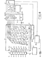
- FIG. 8 represents in more detail the elements 6, 8 and 9 which ensure the analysis of the ultrasonic image 13.
- a set of N frequency changer circuits 2 receives the ultrasonic signals of frequency f 1 which come from the N transducers 1 of the exploring probe.
- the frequency changer circuits 2 receive the local oscillation signal of frequency f 2 supplied by the electric generator 7.
- the beat less than the frequency f 2 - f 1 supplies the row of transducers 3 which emit surface waves 5 of the substrate 4.
- several rows R 1 , R 2 and R 3 of transducer have been arranged. surface wave agents. These advantageously consist of electrodes in the form of interdigitated combs having a common ground connection G.
- the transducers E also consist of interdigital combs deposited on the surface 21 of a substrate 20, for example made of lithium niobate.
- a receiving comb R also deposited on the surface 21, receives the surface waves emitted by the set of transducers E with staggered delays.
- a detector amplifier 24 receives the delayed signals and applies them to the modulating input of the display device 9.
- the device. display 9 is for example constituted by a cathode ray tube whose screen 25 is scanned vertically at a first rate and horizontally at a second slower rate.
- a pulse received by a control circuit 22 closes another stack of switches K 1 , K 2 or K 3 , which connects a row R 1 , R 2 or R 3 of transducers.
- the display device provides an impulse to the ultrasound generator 23.
- an ultrasonic impulse is transmitted to the body to analyze, which insonifies it.
- the ultrasonic energy captured in return by the exploratory probe forms a slice of the ultrasonic image of the section to be displayed. This section moves away from row 3 by successively moving up the rows of analysis R 1 , R 2 and R 3 .
- the signals delivered by the rows R 1 , R 2 and R 3 are distributed in time by the staggered delay line 20 and they in turn modulate the luminance of the spot formed on the screen of the cathode ray tube.
- the scanning of the screen 25 is synchronized with the progression of the surface waves on the substrates 4 and 20, an image visible corresponding to the ultrasonic image is obtained in a time less than the period of recurrence of the ultrasonic emissions.
- the display device of FIGS. 1 and 8 displays a uniformly soundless section.
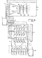
- FIG. 9 we can see the emission part of a visualization device in which the analysis of a section is done by a localized insonification by means of an angularly scannable and focussable beam at different distances from the transmitting scnde.
- the device comprises an exploratory probe comprising a row of M ultrasonic transducers 1 emitting waves of volume frequency f 1 in a propagation medium 11 contained in the tank 10.
- the electrical excitation of the transducers 1 is provided by a set of M frequency changer circuits 2 which receive from the oscillator 7 a local oscillation signal of frequency f.
- the input terminals of circuits 2 are excited by ultrasonic electrical signals of frequency f 2 .
- These signals are generated by rows of surface elastic wave transducers 3 which are arranged on the surface 5 of a substrate 4.
- L N ensures the punctual emission of surface waves directed under several incidences towards the rows of transducers 3.
- the transducers L 1 , L 2 , L i , L N are excited at means of a generator 23 delivering ultra-senses of frequency f 2 .
- a set of switches K 4 communicates the sources L 1 to L N under the control of a circuit 22 which orders the exploration of the body which we want to visualize the cup.
- the circuit 22 also controls several stacks of switches K 1 , K 2 , K 3 which successively connect the rows of switches 3 to the inputs of the frequency changer circuits 2.
- the assembly comprising the exploratory probe 1, the circuits 2 and 7 and one of the rows of transducers 3 has the properties of a lens of predetermined focal length.
- the switches K3 By closing, for example, the switches K3, the image of the sources L 1 to L N is formed along the line 103 in the form of elementary images A 1 to A N.
- the switches K 4 To form the image A i of the source L along the line 103, one of the switches K 4 must be closed. This results in the emission of beam 104 and consequently that of beam 105.
- the means shown in Figure 9 allow to explore point by point the section of a body by means of a converging beam of ultrasound. To visualize the section, it is necessary to capture the ultrasound re-emitted by the body at each point having been selectively insonified.
- the sensor may for example consist of a non-directional transducer element capable of converting the volume waves into a signal modulating the writing beam of the display device. In this case, the control of switches K 1 , K 2 , K 3 and K 4 must be synchronized with the scanning of a display screen.
- the radiation can change direction while remaining parallel.
- the beam 111 is obtained when the emitting source is that located in the middle of the row L 1 , L N ; the beam 110 is obtained when it is the extreme source L N which emits the ultrasound.
- the row of transducers 3 is curved according to an arc of circumference whose center is located in the middle of the row L1 to L N.
- FIG. 11 shows the arrangements that can be used.
- the frequency of the volume waves is noted f V ; that of the local oscillator f L and the two possible beats characterizing the surface waves f ' S and f " S.
- f V the frequency of the volume waves
- f L the local oscillator
- f " S the two possible beats characterizing the surface waves
- the upper beat f " S the sign of phase shift is preserved, which leads to the type of operation illustrated in FIG. understood, the operation with conservation of the sign of the phase shift is advantageous in the case of the projection of a parallel beam. If the radiated beam is divergent, it is necessary to pre- see an auxiliary converging lens upstream of the probe to obtain a real image.
Landscapes
- Physics & Mathematics (AREA)
- Engineering & Computer Science (AREA)
- Radar, Positioning & Navigation (AREA)
- Remote Sensing (AREA)
- Acoustics & Sound (AREA)
- Computer Networks & Wireless Communication (AREA)
- General Physics & Mathematics (AREA)
- Ultra Sonic Daignosis Equipment (AREA)
- Investigating Or Analyzing Materials By The Use Of Ultrasonic Waves (AREA)
- Transducers For Ultrasonic Waves (AREA)
- Special Spraying Apparatus (AREA)
Applications Claiming Priority (2)
| Application Number | Priority Date | Filing Date | Title |
|---|---|---|---|
| FR7730245 | 1977-10-07 | ||
| FR7730245A FR2405485A1 (fr) | 1977-10-07 | 1977-10-07 | Systeme de visualisation par ultrasons d'une coupe mince d'un corps |
Publications (2)
| Publication Number | Publication Date |
|---|---|
| EP0001532A1 true EP0001532A1 (de) | 1979-04-18 |
| EP0001532B1 EP0001532B1 (de) | 1982-04-14 |
Family
ID=9196242
Family Applications (1)
| Application Number | Title | Priority Date | Filing Date |
|---|---|---|---|
| EP78400126A Expired EP0001532B1 (de) | 1977-10-07 | 1978-10-03 | Ultraschallvorrichtung zum Sichtbarmachen eines dünnen Schnittes aus einem Körper |
Country Status (6)
| Country | Link |
|---|---|
| US (1) | US4212206A (de) |
| EP (1) | EP0001532B1 (de) |
| JP (1) | JPS5462685A (de) |
| DE (1) | DE2861741D1 (de) |
| FR (1) | FR2405485A1 (de) |
| NO (1) | NO148576C (de) |
Cited By (2)
| Publication number | Priority date | Publication date | Assignee | Title |
|---|---|---|---|---|
| GB2160973A (en) * | 1984-05-17 | 1986-01-02 | Atomic Energy Authority Uk | Ultrasonic flaw detection |
| FR2631131A1 (fr) * | 1988-05-06 | 1989-11-10 | Thomson Csf | Dispositif a ondes de surface comprenant des moyens de focalisation de ces ondes |
Families Citing this family (24)
| Publication number | Priority date | Publication date | Assignee | Title |
|---|---|---|---|---|
| JPS57200139A (en) * | 1981-06-05 | 1982-12-08 | Olympus Optical Co | Ultrasonic inspecting apparatus |
| JPS5882158A (ja) * | 1981-11-12 | 1983-05-17 | Olympus Optical Co Ltd | 超音波顕微鏡装置 |
| EP0087318B1 (de) * | 1982-02-24 | 1988-02-03 | Kabushiki Kaisha Toshiba | Gerät für Ultraschalldiagnostik |
| US4534221A (en) * | 1982-09-27 | 1985-08-13 | Technicare Corporation | Ultrasonic diagnostic imaging systems for varying depths of field |
| US4751686A (en) * | 1985-05-14 | 1988-06-14 | Olympus Optical Co., Ltd. | Ultrasonic microscope |
| US5840023A (en) * | 1996-01-31 | 1998-11-24 | Oraevsky; Alexander A. | Optoacoustic imaging for medical diagnosis |
| US6405069B1 (en) | 1996-01-31 | 2002-06-11 | Board Of Regents, The University Of Texas System | Time-resolved optoacoustic method and system for noninvasive monitoring of glucose |
| US6309352B1 (en) | 1996-01-31 | 2001-10-30 | Board Of Regents, The University Of Texas System | Real time optoacoustic monitoring of changes in tissue properties |
| US6498942B1 (en) | 1999-08-06 | 2002-12-24 | The University Of Texas System | Optoacoustic monitoring of blood oxygenation |
| US6751490B2 (en) | 2000-03-01 | 2004-06-15 | The Board Of Regents Of The University Of Texas System | Continuous optoacoustic monitoring of hemoglobin concentration and hematocrit |
| EP1620002B1 (de) * | 2003-04-24 | 2012-01-04 | The Board Of Regents, The University Of Texas System | Nichtinvasive blutanalyse durch optische sondierung der venen unter der zunge |
| US9011473B2 (en) | 2005-09-07 | 2015-04-21 | Ulthera, Inc. | Dissection handpiece and method for reducing the appearance of cellulite |
| US8518069B2 (en) | 2005-09-07 | 2013-08-27 | Cabochon Aesthetics, Inc. | Dissection handpiece and method for reducing the appearance of cellulite |
| US9486274B2 (en) | 2005-09-07 | 2016-11-08 | Ulthera, Inc. | Dissection handpiece and method for reducing the appearance of cellulite |
| US10548659B2 (en) | 2006-01-17 | 2020-02-04 | Ulthera, Inc. | High pressure pre-burst for improved fluid delivery |
| US9358033B2 (en) | 2005-09-07 | 2016-06-07 | Ulthera, Inc. | Fluid-jet dissection system and method for reducing the appearance of cellulite |
| US7885793B2 (en) | 2007-05-22 | 2011-02-08 | International Business Machines Corporation | Method and system for developing a conceptual model to facilitate generating a business-aligned information technology solution |
| US9248317B2 (en) | 2005-12-02 | 2016-02-02 | Ulthera, Inc. | Devices and methods for selectively lysing cells |
| US8439940B2 (en) | 2010-12-22 | 2013-05-14 | Cabochon Aesthetics, Inc. | Dissection handpiece with aspiration means for reducing the appearance of cellulite |
| WO2009048969A1 (en) * | 2007-10-09 | 2009-04-16 | Cabochon Aesthetics, Inc. | Ultrasound apparatus with treatment lens |
| US11096708B2 (en) | 2009-08-07 | 2021-08-24 | Ulthera, Inc. | Devices and methods for performing subcutaneous surgery |
| US9358064B2 (en) | 2009-08-07 | 2016-06-07 | Ulthera, Inc. | Handpiece and methods for performing subcutaneous surgery |
| JP7556607B2 (ja) * | 2021-05-11 | 2024-09-26 | ヤマハファインテック株式会社 | 超音波検査装置 |
| WO2022239265A1 (ja) * | 2021-05-11 | 2022-11-17 | ヤマハファインテック株式会社 | 超音波検査装置 |
Citations (3)
| Publication number | Priority date | Publication date | Assignee | Title |
|---|---|---|---|---|
| US3899767A (en) * | 1973-11-15 | 1975-08-12 | Westinghouse Electric Corp | Imaging system |
| FR2287205A1 (fr) * | 1974-10-11 | 1976-05-07 | Thomson Csf | Dispositif d'echo-tomographie ultrasonore rapide |
| FR2367289A1 (fr) * | 1976-10-11 | 1978-05-05 | Anvar | Perfectionnements aux procedes et dispositifs de formation d'image acoustique |
Family Cites Families (2)
| Publication number | Priority date | Publication date | Assignee | Title |
|---|---|---|---|---|
| US3953825A (en) * | 1974-07-12 | 1976-04-27 | The Board Of Trustees Of Leland Stanford Junior University | Electronically focused imaging system and method |
| JPS52107184A (en) * | 1976-03-05 | 1977-09-08 | Hitachi Medical Corp | Device for controlling ultrasonic diagnosis image |
-
1977
- 1977-10-07 FR FR7730245A patent/FR2405485A1/fr active Granted
-
1978
- 1978-10-03 DE DE7878400126T patent/DE2861741D1/de not_active Expired
- 1978-10-03 EP EP78400126A patent/EP0001532B1/de not_active Expired
- 1978-10-07 JP JP12407078A patent/JPS5462685A/ja active Pending
- 1978-10-09 NO NO783409A patent/NO148576C/no unknown
- 1978-10-10 US US05/950,144 patent/US4212206A/en not_active Expired - Lifetime
Patent Citations (3)
| Publication number | Priority date | Publication date | Assignee | Title |
|---|---|---|---|---|
| US3899767A (en) * | 1973-11-15 | 1975-08-12 | Westinghouse Electric Corp | Imaging system |
| FR2287205A1 (fr) * | 1974-10-11 | 1976-05-07 | Thomson Csf | Dispositif d'echo-tomographie ultrasonore rapide |
| FR2367289A1 (fr) * | 1976-10-11 | 1978-05-05 | Anvar | Perfectionnements aux procedes et dispositifs de formation d'image acoustique |
Cited By (2)
| Publication number | Priority date | Publication date | Assignee | Title |
|---|---|---|---|---|
| GB2160973A (en) * | 1984-05-17 | 1986-01-02 | Atomic Energy Authority Uk | Ultrasonic flaw detection |
| FR2631131A1 (fr) * | 1988-05-06 | 1989-11-10 | Thomson Csf | Dispositif a ondes de surface comprenant des moyens de focalisation de ces ondes |
Also Published As
| Publication number | Publication date |
|---|---|
| FR2405485A1 (fr) | 1979-05-04 |
| NO148576C (no) | 1983-11-02 |
| NO783409L (no) | 1979-04-10 |
| EP0001532B1 (de) | 1982-04-14 |
| DE2861741D1 (en) | 1982-05-27 |
| US4212206A (en) | 1980-07-15 |
| FR2405485B1 (de) | 1981-08-28 |
| JPS5462685A (en) | 1979-05-19 |
| NO148576B (no) | 1983-07-25 |
Similar Documents
| Publication | Publication Date | Title |
|---|---|---|
| EP0001532B1 (de) | Ultraschallvorrichtung zum Sichtbarmachen eines dünnen Schnittes aus einem Körper | |
| EP1051700B1 (de) | Kontakt-ultraschallwandler mit mehreren elementen | |
| EP0342757B1 (de) | Ultraschall-Echographiegerät mit steuerbarer Phasenkohärenz | |
| US7089796B2 (en) | Time-reversed photoacoustic system and uses thereof | |
| US5615675A (en) | Method and system for 3-D acoustic microscopy using short pulse excitation and 3-D acoustic microscope for use therein | |
| NL1025267C2 (nl) | Werkwijze en inrichting voor het vanaf een oppervlak van een voorwerp zoals een pijpleiding of een menselijk lichaam onderzoeken van het inwendige materiaal van het voorwerp met behulp van ultrasoon geluid. | |
| US7926350B2 (en) | Method for the non-destructive inspection of a test body using ultrasound | |
| EP0709673A1 (de) | Vorrichtung zur zerstörungsfreien Prüfung von rohrförmigen Hohlkörpers mit Ultraschall | |
| JP4220102B2 (ja) | 動的変化検出方法、動的変化検出装置及び超音波診断装置 | |
| EP0124442B1 (de) | Verfahren und Vorrichtung zur akustischen Holographie bei Verwendung eines räumlich begrenzten Ultraschallstrahlenbündels | |
| FR2589247A1 (fr) | Appareil d'exploration de milieux par echographie ultrasonore comprenant un reseau d'elements transducteurs piezoelectiques | |
| EP0543445A1 (de) | Untersuchungsgerät von Medien mittels Ultraschall-Echographie | |
| EP0872742A1 (de) | Verfahren und Vorrichtung zur Verarbeitung von aus einer Volumenstruktur übertragenen oder gebeugten Signalen reflektierter Wellen zur Erkundung oder Analyse der Struktur | |
| FR2566130A1 (fr) | Appareil d'examen de milieux par echographie ultrasonore | |
| WO2020240131A1 (fr) | Systeme de mesure acoustique picoseconde a double faisceaux sondes | |
| EP0825453A1 (de) | Verfahren und Anordnung zur Bearbeitung von Signalen, welche durch ein Volumenstruktur reflektierte oder übertragene Wellen darstellen, um eine Forschung und Analyse der Struktur auszuführen | |
| Ashkenazi et al. | High frequency ultrasound imaging using Fabry-Perot optical etalon | |
| EP0040566B1 (de) | Echographisches Gerät mit dynamischer Fokussierung und Sektorabtastung | |
| FR2660436A1 (fr) | Microscope acoustique pour analyser un objet en surface ou en profondeur. | |
| FR2737011A1 (fr) | Procede et dispositif d'imagerie parallele | |
| JPH07270386A (ja) | 超音波顕微鏡 | |
| Gunarathne | A new real-time high speed ultrasonic imaging system | |
| FR2476867A1 (fr) | Appareil de formation d'image en balayage de type b electronique a partir d'ondes ultrasonores | |
| JPH0339265B2 (de) | ||
| FR2507324A1 (fr) | Procede de localisation de source acoustique, dispositif mettant en oeuvre un tel procede, et appareil de saisie de donnees graphiques en faisant application |
Legal Events
| Date | Code | Title | Description |
|---|---|---|---|
| PUAI | Public reference made under article 153(3) epc to a published international application that has entered the european phase |
Free format text: ORIGINAL CODE: 0009012 |
|
| AK | Designated contracting states |
Designated state(s): BE DE GB NL |
|
| 17P | Request for examination filed | ||
| GRAA | (expected) grant |
Free format text: ORIGINAL CODE: 0009210 |
|
| AK | Designated contracting states |
Designated state(s): BE DE GB NL |
|
| REF | Corresponds to: |
Ref document number: 2861741 Country of ref document: DE Date of ref document: 19820527 |
|
| PGFP | Annual fee paid to national office [announced via postgrant information from national office to epo] |
Ref country code: BE Payment date: 19830930 Year of fee payment: 6 |
|
| PGFP | Annual fee paid to national office [announced via postgrant information from national office to epo] |
Ref country code: DE Payment date: 19831028 Year of fee payment: 6 |
|
| PGFP | Annual fee paid to national office [announced via postgrant information from national office to epo] |
Ref country code: NL Payment date: 19831031 Year of fee payment: 6 |
|
| PG25 | Lapsed in a contracting state [announced via postgrant information from national office to epo] |
Ref country code: BE Effective date: 19841031 |
|
| BERE | Be: lapsed |
Owner name: THOMSON-CSF Effective date: 19841003 |
|
| PG25 | Lapsed in a contracting state [announced via postgrant information from national office to epo] |
Ref country code: NL Effective date: 19850501 |
|
| GBPC | Gb: european patent ceased through non-payment of renewal fee | ||
| NLV4 | Nl: lapsed or anulled due to non-payment of the annual fee | ||
| PG25 | Lapsed in a contracting state [announced via postgrant information from national office to epo] |
Ref country code: DE Effective date: 19850702 |
|
| PG25 | Lapsed in a contracting state [announced via postgrant information from national office to epo] |
Ref country code: GB Effective date: 19881117 |
|
| PLBE | No opposition filed within time limit |
Free format text: ORIGINAL CODE: 0009261 |
|
| STAA | Information on the status of an ep patent application or granted ep patent |
Free format text: STATUS: NO OPPOSITION FILED WITHIN TIME LIMIT |