EP0001652B1 - Arracheuse pour récolter des racines - Google Patents
Arracheuse pour récolter des racines Download PDFInfo
- Publication number
- EP0001652B1 EP0001652B1 EP19780200211 EP78200211A EP0001652B1 EP 0001652 B1 EP0001652 B1 EP 0001652B1 EP 19780200211 EP19780200211 EP 19780200211 EP 78200211 A EP78200211 A EP 78200211A EP 0001652 B1 EP0001652 B1 EP 0001652B1
- Authority
- EP
- European Patent Office
- Prior art keywords
- conveyor
- soil
- tubers
- pairs
- behind
- Prior art date
- Legal status (The legal status is an assumption and is not a legal conclusion. Google has not performed a legal analysis and makes no representation as to the accuracy of the status listed.)
- Expired
Links
- 239000002689 soil Substances 0.000 claims description 15
- 235000016068 Berberis vulgaris Nutrition 0.000 claims description 8
- 241000335053 Beta vulgaris Species 0.000 claims description 8
- 238000004140 cleaning Methods 0.000 claims description 7
- 238000006073 displacement reaction Methods 0.000 claims description 5
- 238000000926 separation method Methods 0.000 description 1
Images
Classifications
-
- A—HUMAN NECESSITIES
- A01—AGRICULTURE; FORESTRY; ANIMAL HUSBANDRY; HUNTING; TRAPPING; FISHING
- A01D—HARVESTING; MOWING
- A01D33/00—Accessories for digging harvesters
-
- A—HUMAN NECESSITIES
- A01—AGRICULTURE; FORESTRY; ANIMAL HUSBANDRY; HUNTING; TRAPPING; FISHING
- A01D—HARVESTING; MOWING
- A01D19/00—Digging machines with centrifugal wheels, drums or spinners
- A01D19/12—Digging machines with centrifugal wheels, drums or spinners with working tools arranged on an approximately vertical axis
- A01D19/14—Digging machines with centrifugal wheels, drums or spinners with working tools arranged on an approximately vertical axis with one screening wheel
-
- A—HUMAN NECESSITIES
- A01—AGRICULTURE; FORESTRY; ANIMAL HUSBANDRY; HUNTING; TRAPPING; FISHING
- A01D—HARVESTING; MOWING
- A01D23/00—Topping machines
- A01D23/06—Topping machines with collecting and depositing devices for the tops; Devices for protecting the tops against damage
-
- A—HUMAN NECESSITIES
- A01—AGRICULTURE; FORESTRY; ANIMAL HUSBANDRY; HUNTING; TRAPPING; FISHING
- A01D—HARVESTING; MOWING
- A01D27/00—Machines with both topping and lifting mechanisms
- A01D27/02—Machines with both topping and lifting mechanisms with rigid tools
-
- A—HUMAN NECESSITIES
- A01—AGRICULTURE; FORESTRY; ANIMAL HUSBANDRY; HUNTING; TRAPPING; FISHING
- A01D—HARVESTING; MOWING
- A01D23/00—Topping machines
- A01D23/02—Topping machines cutting the tops before being lifted
- A01D2023/026—Devices with movable knives for topping, e.g. rotatable cutting disks
- A01D2023/028—Cutters rotating around a shaft forming a cutting rotor
Definitions
- the invention relates to a device for lifting tuberous crops or the like, particularly beet, comprising a wheeled frame carrying at least three pairs of digging members for raising tubers out of the soil, behind at least one of said pairs one or more conveyors being arranged above soil-level for lateral displacement of the crop, each leading to an endless conveyor for feeding off and cleaning said tubers and each provided with crop engaging elements moving around from an active part to a return part of said conveyor, said return part being located behind said active part viewed in the travelling direction of the device.
- the invention has for its object to improve the known device set forth above by additional measures by which not only the structural length can be minimized by also lifting the tubers out of the soil and cleaning them are performed more effectively.
- said lateral displacing conveyor is formed by a flexible member arranged at a certain distance above the soil and carrying downwardly protruding pins and guided around two return rollers having an upstanding roller axis.
- pins with a non-circular cross-section and to adapt each pin to be mounted so as to be adjustable about its longitudinal axis with respect to the flexible element. In this way the space between adjacent pins can be varied, which may be important for a given kind of tuberous crop to be lifted and for the conditions of the soil.
- said lateral displacing conveyor is formed by a plurality of rotatably driven upstanding shafts arranged side by side, whereas said protruding pins are fastened to said shafts at different heights.
- the device is provided with a grating supported by the frame arranged above a rotating conveyor formed by two concentric annular members mutually connected by rods, said grating being supported above at least a part OT the region enclosed by the inner angular member.
- Said grating may be fixed to the frame or may be oscillated respectively.
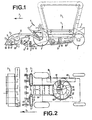
- the device shown in Figs. 1 to 5 mainly comprises a frame 1 adapted to be moved on four wheels 2 on a field in the direction indicated by the arrow P 1.
- the device is propelled by an engine 3 driving the front wheels of the device, whereas the rear wheels can be steered by the steering wheel near the driver seat 4.
- the left stripping section 5 (which is the subject of our European Patent Application No. 80201011.6 published with No. 0026960) mainly consists of a clapper rotor 51 rotating in the direction indicated by the arrow P 2 and serving to strike the leaves from the beet.
- the separated leaves arrive in the direction of the arrow P 3 at the leaf remover 52, which laterally conducts the leaves away and deposits them in a swath on the soil at the side of the machine.
- the leaf stripper 5 comprises one or more cutting members 53, each of which is adapted to move up and down on a pivotal arm 54.
- the arm 54 is pivotable about a pivotal shaft 55 at the front of the leaf stripping section 5.
- the digging section 6 comprises pairs of digging members 61 described in the above mentioned Dutch patent application 7513829. Each pair of digging members raises the beet out of the soil so that it will lie on the surface of the soil, whilst the separating members 62 raise the beet further upwards and transport it to the rear.
- the separating members 62 may be disposed between the pairs of digging members 61 as well as between the digging members of a pair.
- t1;e section 7 conveying in a transverse direction is formed by two conveying elements located each behind those digging members which are located each behind those digging members which are located at the side of the conveying section 8 in the transport direction.
- the conveying elements 71 each consist of a sequence of vertically or substantially vertically extending tines moving along a closed path. On the side of the closed path of the vertical tines 71 facing the digging members 61 the beet raised above the soil will
- the vertically extending tines 71 are fastened to an endless, flexible element 72, which is guided around two reversing elements 73 rotating about a vertical axis.
- One of the shafts of the reversing elements 73 is driven so that the tines will describe the compulsory path.
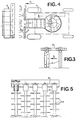
- the tines have a non-circular cross-section (see Fig. 3) so that the same tines can be mounted in two positions with respect to the flexible element 72 (see the difference in mounting on the left- and righthand sides of Fig. 3). Obviously both the resistance exerted by the soil and the distance between the tines can thus be varied at will.
- the conveying section 8 is formed by an elevator 81, the front end of which joins the delivery ends of the transverse conveyors 7 and the rear end of which terminates above a rotating wheel 82 of the conveying section.
- the elvator 81 may be constructed in any way and is formed in the embodiment shown by an endless belt, which preferably constitutes, in addition, a sieve belt in order to carry out a first separation between the crop and the earth.
- the rotating wheel 82 is equipped with an outer rim 83 and a concentric inner rim 84. Between these two rims extend rod-like elements 85 substantially in a radial direction, which carry along the tubers in the direction indicated by the arrow P 5 (see Fig. 2) and deliver them on a conveying belt 86 lying out of the scope of this invention for transport to the bunker 9.
- a grating 87 is arranged, against which the tubers carried by the elevator 81 are thrown.
- This grating an effective cleaning of the tubers is ensured, since the earth is pushed off the tubers as a result of the change in the direction of movement.
- the loosened earth can drop unhindered through the grating 87 across the region inside the inner rim 84, since only four spokes are arranged between the driving shaft 88 and the inner rim 84 for rotating the wheel around the shaft 88.
- the grating 87 may have any shape and can extend through the full region inside the inner rim 84.
- Figs. 4 and 5 illustrate a second embodi.. ment of the transverse conveying element.
- the pins moved along a closed path are formed in this case by radially directed groups of pins 74, each group being fastened to an upwardly extending rotatable shaft 75.
- the shafts are all driven in the same sense by appropriate driving means, in this case a chain 76. so that on the side facing the digging members 61 the pins 74 again perform a conveying operation in the direction of the arrow P 4 in Fig. 4.
Landscapes
- Life Sciences & Earth Sciences (AREA)
- Environmental Sciences (AREA)
- Harvesting Machines For Root Crops (AREA)
Claims (6)
Priority Applications (1)
| Application Number | Priority Date | Filing Date | Title |
|---|---|---|---|
| DE8080201011T DE2862362D1 (en) | 1977-10-25 | 1978-09-26 | Device for removing leaf of tuberous crop |
Applications Claiming Priority (2)
| Application Number | Priority Date | Filing Date | Title |
|---|---|---|---|
| NL7711703A NL7711703A (nl) | 1977-10-25 | 1977-10-25 | Rooiinrichting voor knolgewassen. |
| NL7711703 | 1977-10-25 |
Related Child Applications (1)
| Application Number | Title | Priority Date | Filing Date |
|---|---|---|---|
| EP80201011.6 Division-Into | 1978-09-26 |
Publications (2)
| Publication Number | Publication Date |
|---|---|
| EP0001652A1 EP0001652A1 (fr) | 1979-05-02 |
| EP0001652B1 true EP0001652B1 (fr) | 1982-02-24 |
Family
ID=19829403
Family Applications (2)
| Application Number | Title | Priority Date | Filing Date |
|---|---|---|---|
| EP19800201011 Expired EP0026960B1 (fr) | 1977-10-25 | 1978-09-26 | Dispositif pour effeuiller les betteraves |
| EP19780200211 Expired EP0001652B1 (fr) | 1977-10-25 | 1978-09-26 | Arracheuse pour récolter des racines |
Family Applications Before (1)
| Application Number | Title | Priority Date | Filing Date |
|---|---|---|---|
| EP19800201011 Expired EP0026960B1 (fr) | 1977-10-25 | 1978-09-26 | Dispositif pour effeuiller les betteraves |
Country Status (2)
| Country | Link |
|---|---|
| EP (2) | EP0026960B1 (fr) |
| NL (1) | NL7711703A (fr) |
Families Citing this family (6)
| Publication number | Priority date | Publication date | Assignee | Title |
|---|---|---|---|---|
| DE3140976A1 (de) * | 1981-10-15 | 1983-05-11 | Werner 4787 Geseke Schulte | Ruebenblatterntevorrichtung |
| EP0102016B1 (fr) * | 1982-08-12 | 1987-03-11 | Wilhelm Stoll Maschinenfabrik GmbH | Machine à récolter plusieurs rangées de betteraves, de préférence attelée à un tracteur et poussée par celui-ci |
| DE3237249C2 (de) * | 1982-10-07 | 1986-06-12 | Konrad 8401 Untersanding Hendlmeier | Vorrichtung zum Roden von Wurzelfrüchten |
| FR2578711B1 (fr) * | 1985-03-14 | 1988-07-22 | Dugave Ets | Arracheuse automotrice frontale endiviere neuf rangs |
| GB2176985B (en) * | 1985-07-05 | 1989-05-04 | Nat Res Dev | Root crop harvester |
| CN106304936B (zh) * | 2016-08-10 | 2019-04-19 | 游小彩 | 一种大蒜花生土豆联合收割机 |
Family Cites Families (11)
| Publication number | Priority date | Publication date | Assignee | Title |
|---|---|---|---|---|
| DE1719597U (de) * | 1956-01-25 | 1956-03-29 | Heinrich Lanz Ag | Wurzelfruchterntemaschine mit kreisfoermiger, rotierender verleseeinrichtung. |
| DE1053228B (de) * | 1956-11-17 | 1959-03-19 | Heinrich Lanz Ag | Verfahren und Vorrichtung zum Ernten von Rueben |
| FR87655E (fr) * | 1962-10-19 | 1966-06-03 | Appareil nettoyeur pour ramasseuses de betteraves, de pommes de terre et analogues | |
| US3208168A (en) * | 1963-01-14 | 1965-09-28 | Henschen Ind Corp | Universally cushioned dual drive mechanism |
| DE1482245C3 (de) * | 1964-10-24 | 1973-10-25 | Ernst 7326 Heiningen Weichel | Selbstladewagen zum Ernten von Hackfruchten |
| AT253286B (de) * | 1965-01-20 | 1967-03-28 | Rasmussen Hans Carsten | Rübenhebemaschine |
| FR1525203A (fr) * | 1967-04-03 | 1968-05-17 | Machine à effeuiller et décolleter les betteraves | |
| DE2153543A1 (de) * | 1971-10-27 | 1973-05-03 | Sueddeutsche Zucker Ag | Selbstfahrgestell mit ruebenernteausruestung |
| BE834326A (nl) * | 1975-10-09 | 1976-02-02 | Bietenrooimachine | |
| NL7513829A (en) * | 1975-11-26 | 1977-05-31 | Eugene Jozeph Eduardus Heyens | Root crop lifting machine - has transporter extending transversely between tool and cleaner conveyor behind |
| DE2647282A1 (de) * | 1976-10-20 | 1978-04-27 | Kleine Franz Fa | Mehrreihige ruebenerntemaschine |
-
1977
- 1977-10-25 NL NL7711703A patent/NL7711703A/xx not_active Application Discontinuation
-
1978
- 1978-09-26 EP EP19800201011 patent/EP0026960B1/fr not_active Expired
- 1978-09-26 EP EP19780200211 patent/EP0001652B1/fr not_active Expired
Also Published As
| Publication number | Publication date |
|---|---|
| EP0026960A1 (fr) | 1981-04-15 |
| EP0026960B1 (fr) | 1984-01-11 |
| EP0001652A1 (fr) | 1979-05-02 |
| NL7711703A (nl) | 1979-04-27 |
Similar Documents
| Publication | Publication Date | Title |
|---|---|---|
| US4234045A (en) | Harvesting machine feeder apparatus | |
| EP0001652B1 (fr) | Arracheuse pour récolter des racines | |
| US1906498A (en) | Windrow harvester apparatus and method | |
| US3712039A (en) | Crop pick-up harvester | |
| US1276903A (en) | Potato-digger. | |
| CA1109683A (fr) | Recolteuse de tubercules comestibles | |
| US2071325A (en) | Vegetable digger | |
| US1114390A (en) | Beet pulling and topping machine. | |
| GB1601478A (en) | Root harvesters | |
| US2011925A (en) | Tractor corn picker | |
| SE452240B (sv) | Rensverk vid maskin for upptagning av rotfrukter | |
| US2430665A (en) | Beet harvester with topper | |
| US2791076A (en) | Root crop harvesting machines | |
| US2560974A (en) | Stripper type cotton harvester | |
| US3427794A (en) | Mobile cucumber harvester | |
| US4059943A (en) | Harvester apparatus | |
| US1185785A (en) | Beet-harvester. | |
| SU1253420A3 (ru) | Машина дл уборки корнеплодов | |
| US1729648A (en) | Corn harvester | |
| US1657183A (en) | Beet harvester | |
| US1321326A (en) | Peanut-harvester | |
| US1589502A (en) | Beet harvester | |
| US2956385A (en) | Vine stripping harvester | |
| KR200207007Y1 (ko) | 농산물 채취기 | |
| US2580432A (en) | Beet harvester with lifter |
Legal Events
| Date | Code | Title | Description |
|---|---|---|---|
| PUAI | Public reference made under article 153(3) epc to a published international application that has entered the european phase |
Free format text: ORIGINAL CODE: 0009012 |
|
| AK | Designated contracting states |
Designated state(s): BE DE FR GB NL |
|
| 17P | Request for examination filed | ||
| GRAA | (expected) grant |
Free format text: ORIGINAL CODE: 0009210 |
|
| AK | Designated contracting states |
Designated state(s): BE DE FR GB NL |
|
| REF | Corresponds to: |
Ref document number: 2861645 Country of ref document: DE Date of ref document: 19820325 |
|
| PGFP | Annual fee paid to national office [announced via postgrant information from national office to epo] |
Ref country code: GB Payment date: 19930913 Year of fee payment: 16 |
|
| PGFP | Annual fee paid to national office [announced via postgrant information from national office to epo] |
Ref country code: BE Payment date: 19930928 Year of fee payment: 16 |
|
| PGFP | Annual fee paid to national office [announced via postgrant information from national office to epo] |
Ref country code: FR Payment date: 19930929 Year of fee payment: 16 |
|
| PGFP | Annual fee paid to national office [announced via postgrant information from national office to epo] |
Ref country code: NL Payment date: 19930930 Year of fee payment: 16 Ref country code: DE Payment date: 19930930 Year of fee payment: 16 |
|
| PG25 | Lapsed in a contracting state [announced via postgrant information from national office to epo] |
Ref country code: GB Effective date: 19940926 |
|
| PG25 | Lapsed in a contracting state [announced via postgrant information from national office to epo] |
Ref country code: BE Effective date: 19940930 |
|
| BERE | Be: lapsed |
Owner name: HEYENS EUGENE JOSEPH EDUARDUS Effective date: 19940930 |
|
| PG25 | Lapsed in a contracting state [announced via postgrant information from national office to epo] |
Ref country code: NL Effective date: 19950401 |
|
| NLV4 | Nl: lapsed or anulled due to non-payment of the annual fee | ||
| GBPC | Gb: european patent ceased through non-payment of renewal fee |
Effective date: 19940926 |
|
| PG25 | Lapsed in a contracting state [announced via postgrant information from national office to epo] |
Ref country code: FR Effective date: 19950531 |
|
| PG25 | Lapsed in a contracting state [announced via postgrant information from national office to epo] |
Ref country code: DE Effective date: 19950601 |
|
| REG | Reference to a national code |
Ref country code: FR Ref legal event code: ST |
|
| PLBE | No opposition filed within time limit |
Free format text: ORIGINAL CODE: 0009261 |
|
| STAA | Information on the status of an ep patent application or granted ep patent |
Free format text: STATUS: NO OPPOSITION FILED WITHIN TIME LIMIT |