EP0001683A1 - Un dispositif de commande dépendant de la vitesse pour remettre en position initiale un dispositif de manoeuvre - Google Patents
Un dispositif de commande dépendant de la vitesse pour remettre en position initiale un dispositif de manoeuvre Download PDFInfo
- Publication number
- EP0001683A1 EP0001683A1 EP78300415A EP78300415A EP0001683A1 EP 0001683 A1 EP0001683 A1 EP 0001683A1 EP 78300415 A EP78300415 A EP 78300415A EP 78300415 A EP78300415 A EP 78300415A EP 0001683 A1 EP0001683 A1 EP 0001683A1
- Authority
- EP
- European Patent Office
- Prior art keywords
- distance
- article
- signal
- responsive
- predetermined
- Prior art date
- Legal status (The legal status is an assumption and is not a legal conclusion. Google has not performed a legal analysis and makes no representation as to the accuracy of the status listed.)
- Granted
Links
- 230000000977 initiatory effect Effects 0.000 title claims description 44
- 230000001419 dependent effect Effects 0.000 title abstract 2
- 238000001514 detection method Methods 0.000 claims description 11
- 238000011144 upstream manufacturing Methods 0.000 claims description 10
- 238000002372 labelling Methods 0.000 abstract description 6
- 230000001934 delay Effects 0.000 abstract description 4
- 238000004519 manufacturing process Methods 0.000 abstract description 2
- 238000005259 measurement Methods 0.000 description 4
- 239000000853 adhesive Substances 0.000 description 2
- 230000001070 adhesive effect Effects 0.000 description 2
- 238000000034 method Methods 0.000 description 2
- 238000010276 construction Methods 0.000 description 1
- 238000010586 diagram Methods 0.000 description 1
- 239000003292 glue Substances 0.000 description 1
- 230000003287 optical effect Effects 0.000 description 1
- 230000000717 retained effect Effects 0.000 description 1
- 230000003068 static effect Effects 0.000 description 1
Images
Classifications
-
- B—PERFORMING OPERATIONS; TRANSPORTING
- B65—CONVEYING; PACKING; STORING; HANDLING THIN OR FILAMENTARY MATERIAL
- B65C—LABELLING OR TAGGING MACHINES, APPARATUS, OR PROCESSES
- B65C9/00—Details of labelling machines or apparatus
- B65C9/40—Controls; Safety devices
- B65C9/42—Label feed control
-
- B—PERFORMING OPERATIONS; TRANSPORTING
- B65—CONVEYING; PACKING; STORING; HANDLING THIN OR FILAMENTARY MATERIAL
- B65C—LABELLING OR TAGGING MACHINES, APPARATUS, OR PROCESSES
- B65C9/00—Details of labelling machines or apparatus
- B65C9/40—Controls; Safety devices
Definitions
- the invention relates to a velocity compensator for controlling the initiation of an actuator where an article is moved along a path through a work station and the actuator performs a work operation on the article at the work station with the actuator requiring an actuation period from the time it is initiated to perform the work operation.
- the invention also relates to an apparatus for performing a work operation on an article as the article is moved along a path through a work station, said apparatus comprising means responsive to an actuation signal for performing a work operation on the article and having an actuation period extending from the time of said actuation signal to the completion of the work operation, said work operation being completed at said work station.
- label application articles to be labelled are continuously conveyed past a label applicator.
- the label applicator applies a label to each of the articles as the article is moved through a labelling station.
- the label applicator releasably retains a label at a first location.
- an actuation signal is provided commanding that the label applicator immediately transfer the label from the first location to the article.
- the actuation period is the period of time from the actuation signal until the adhesive face of the label contacts the article.
- This invention provides a single, inexpensive velocity compensator.
- the velocity compensator of this invention can be used with many different apparatuses which perform work operations on articles moved past the apparatus.
- the velocity compensator can be used with a label applicator, a glue applicator, an ejector for removing an article from the line, etc.
- the actuation period for a given apparatus is normally substantial: constant for any given work operation.
- the invention uses this to advantage by measuring the distance which the article travels during the actuation period. This travel distance equals the distance upstream of the work station where the actuation signal should be given.
- article location relative to the work station is known at the cycle initiation location, i.e., the location at which the above- mentioned measurement of the travel distance is initiated, article location is unknown at the completion of this measurement.
- article location immediately following this measurement need not be known.
- the article is again located when it reaches a secondary initiation location.
- the secondary initiation location is spaced a first predetermined distance downstream of the cycle initiation location so that ample time is provided for the measurement of the travel distance.
- the secondary initiation location is spaced a second predetermined distance upstream of the work station.
- Measuring means is provided for measuring distances having Iengths equal to the second predetermined distance referred to above.
- the measuring means reduces the second predetermined distance by the travel distance to thereby define a remaining distance.
- the measuring means is responsive to the article reaching the secondary initiation location to provide an actuation signal after the article has moved the remaining distance. This ensures that the actuation signal will be provided at a distance equal to the travel distance upstream from the work station.
- the invention is based on the assumption that article velocity will not be materially varied after the travel distance is measured. This is a safe and realistic assumption because the travel distance is itself an average of instantaneous variations in line speed. Furthermore, by having the cycle initiation location close to the work station, there is little opportunity for major line spesd changes prior to completion of the work operation. For example, the cycle initiation location may be only four inches from the work station. The travel distance should not exceed the second predetermined distance and the latter should be no greater than the first predetermined distance. ;
- a pulse generator can be used to provide a pulse having a width or duration corresponding to the actuation period.
- the duration of the pulse can be varied so that the same velocity compensator can be used with different apparatuses.
- the pulse generator can be initiated by a conventional article detector, such as a photocell or a suitch.
- a shaft encoder or other device for generating pulses representing an incremental distance of article travel can be utilized to provide data relating to article speed.
- the measuring means can advantageously include a shift register. py applying the pulse from the pulse generator to the data input of the shift register and clocking the shift register with the pulses from the shaft encoder, data corresponding to velocity times time or distance is fed directly into the shift register.
- the shift register has a bit capacity corresponding to the second predetermined distance. Accordingly, by again initiating the clocking of the shift register when the article reaches the secondary initiation location and by clocking the shift register at a rate related to the speed of movement of the article, the first bit of data is clocked out of the shift register when the article is upstream of the work station by a distance equal to the travel distance. This simple and inexpensive implementation gives very accurate results.
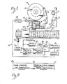
- Fig. 1 shows a label applicator 11 having a velocity compensator 13 incorporated therein.
- the label applicator I1 is merely illustrative of the kind of apparatus or actuator with which the velocity compensator 13 can be utilized.
- the label applicator 11 can be of various different canstructions.
- the label applicator 11 may be of the construction shown and described in U.S. Patent No. 3,885,705.
- the label applicator 11 includes a supporting structure 14, a supply reel 15, and a take-up reel 17. Both of the reels 15 and 17 are rotatably mounted on the supporting structure 14.
- a backing strip or carrier strip 19 is wound on the supply reel 15, and a plurality of labels 21 are adhesively secured to and carried by the backing strip.
- the backing strip 19 extends from the supply reel 15 over guide rollers 23 mounted on the supporting structure 10 over a peeling bar 25, and between a drive roller 27 and an idler roller 29 to the take-up reel 17.
- the label applicator 11 also includes a housing or vacuum box 31 defining a chamber 33.
- the housing 31 includes a previous wall section in the form of a grid 35, one end of which lies closely adjacent the peeling bar 25.
- the chamben 33 is evacuated to a pressure less than atmospheric so that a suction force is applied through the grid 35.
- Air under greater than atmospheric pressure is supplied from a source Cnot shown) through the controllable automatic valve 37, which may be a solenoid valve, and a conduit 39 to a'manifold 41. From the manifold 41, the air is transmitted through a plurality of flexible tubes 43 to the grid.
- a blast of air under pressure is supplied to the grid 35.
- the drive roller 27 is driven intermittently and for predetermined periods to draw the backing strip 19 across the peeling bar 25. This causes the peeling bar 25 to function in a conventional manner to remove the labels 21 and supply them in sequence to the grid 35.
- a label 21 has been removed from the backiag strip 19 and supplied to the grid 35.
- the label 21 is releasably retained on the grid 35 by the vacuum pressure within the chamber 33.
- an actuation signal is provided by the velocity compensator 13 to the valve 37 to cause the valve to momentarily open. This provides a blast of air under pressure to the grid 35 of sufficient force to remove the label 21 from the grid and transfer it to the article 45.
- the label 21 is retain" on the article 45 by the adhesive carried on one face of the label.
- Some measurable time is required from the initiation of the actuation signal until the label 21 contacts the article 45. This is the actuation period for the label applicator 11, and it includes all of the electrical, mechanical and other delays inherent in opening the vaive 37 permitting the.air preasure to rise sufficiently at the discharge ends of the tubes 43 at the grid 35 to remove the label 21, and the time required for the label to travel the distance between the grid 35 and the adjacent surface of the article 45.
- the article 45 as well as other articles (not shown) are moved via a conveyor 47 through a labelling station at which the article 45 receives the label 21.
- the conveyor 47 moves continuously; however, as is often the case, conveyor speed may vary.
- the primary function of the velocity compensator 13 is to provide the actuation signal when the article 45 is sufficiently upstream of the labelling station so that the label 21 will be applied precisely-to the desired location on the article.
- the velocity compensator 13 includes a sensor or detector 49. which, in the embodiment illustrated, is mounted on the supporting structure 14 closely adjacent the labelling station.
- the detector 49 may be any device which is capable of providing a detection signal when a suitable reference location on the article 45, such as the leading edge of the article 45, reaches a known position referred to herein as a cycle initiation location.
- detector 49 may be a photocell, a switch, a pneumatically operated detector, etc. In the embodiment illustrated, the detector 49 is a photocell detector.
- a shaft encoder 51 in the form of an optical encoder is driven by a motor 52 which drives the conveyor 47.
- the shaft encoder 51 provides a velocity signal in the form of pulses with each of the pulses representing an incremental distance of conveyor 47 and article 45 movement.
- the detection signal from the detector 49 is transmitted to the set terminal of a set/reset flip-flop 53 to set the flip-flop to its high or "1" state.
- the output from the flip-flop 53 is provided to the data terminal of a shift register 55, which in the embodiment illustrated, is a serial in, serial out shift register.
- the velocity signal from the shaft encoder 51 is applied to the clock terminal of the shift register 55. Accordingly, the signal from the flip-flop 53 is loaded into the shift register 55 at a clock rate established by the speed of movement of the article 45.
- the detection signal is also applied to a pulse generator 57 which may be a one-shot pulse generator.
- the pulse generator 57 provides a single pulse having a predetermined, but adjustable, pulse width or duration.
- the pulse width or pulse duration can be manually adjusted to equal the actuation period of the label applicator 11.
- the single pulse output of the pulse generator 57 can be considered a timing signal.
- the timing signal from the pulse generator 57 is applied to one input of an OR gate 59 and to the data terminal of a shift register 61. which may be identical to the shift register 55.
- the output of the OR gate 59 is applied to one input of an AND gate 63 and the other input of the AND gate 63 is coupled to receive the velocity signal from the shaft encoder 51. Accordingly, the AND gate is immediately enabled and its output, which is the velocity signal from the shaft encoder 51, is applied to the clock terminal of. the shift register 61.
- the timing signal from the pulse generator 57 terminates, the AND gate 63 is inhibited and data is no longer shifted in the shift register 61.
- the bit capacity of the shift register 61 is selected so that its capacity is not fully taken before the end of the timing signal from the pulse generator 57.
- the secondary initiation signal is transmitted to the other input of the OR gate 59 to enable this gate.
- the output cf t OR gate 59 again enables the AND gate 63 so thereafter the data in the shift register 61 can be clocked through the shift register by the velocity signal from the shaft encoder 51.
- the data first loaded into the shift register 61 is provided at the output of the shift regin 61 to provide an actuation signal.
- the actuation signal can be pic- Determinated in any suitable manner so that it can be used to open the valve,
- the output from the shift register 61 actuates a one-shot generator 65 which in turn operates driver 67 which provides the actuation signal in usable form to the val 37 to momentarily open the valve.
- the operation of the velocity compensator 13 can best be understood by reference to Fig. 2.
- the detector 49 detects the articl 45 and provides the detection signal at a cycle initiation location 69 which is spaced a known distance from a work station 71 with such distant being represented by the line between these two locations.
- the work station 71 is the location of the leading edge of the article 45 when the label 21 first contacts the article 45. If the compensator keys off of a reference location on the article 45 other than the leading edge, such as the trailing edge, then the work station 71 is the location of such reference when the label 21 first contacts the article 45.
- a secondary initiation location 73 lies at a known position intermediata the cycle initiation location 69 and the work station 71.
- the secondary initiation location 73 is the location of the article 45 when the secondary initiation signal is provided by the shift register 55 to the shift register 61 to restart the clocking of the shift register 61.
- the location 73 is spaced from the location 69 by a first predetermired distance, and the location 73 is spaced from the work station 71 by a second predetermined distance.
- the first predetermined distance in the embodiment illustrated corresponds to the bit capacity of the shift register 55 and the second predetermined distance corresponds to the bit capacity of the shift register 61.
- the primary function of the shift register 55 is to measure the first predetercained distance and thus to establish the location of the secondary initiation location 73.
- the location of the secondary initiation location 73 could be accomplishe in other ways, such as by the use of a detector or sensor at the secondary initiation location 73.
- the first and second predetermined distances should be equal.
- the shift registers 55 and 61 may be identical.
- the detector 49 responds by providing the detection signal to the pulse generator 57 and to the flip-flop 53.
- the output from the flip-flop 53 is loaded into the shift register 55 by the velocity signal com the shaft encoder 51 as described above so that the shift register 55 immediately begins tracking the article 45 along the first predetermined distance.
- the pulse generator 57 provides the timing signal to the shift register 61 so that this data is loaded into the shift register 61 as described above at the clock rate established by et velocity signal from the shaft encoder 51.
- the information loaded into the shift register 61 is velocity of the article 45 times time where time is the actuation period. Because velocity times time equals distance, a distance corresponding-to the distance that the article 45 travels during the - actuation period, i.e., the travel distance, is loaded into the shift register 61.
- the travel distance uses up portions of the first and second predetermined distances as shown in Fig. 2, but it is not greater than either of the predetermined distances.
- the shift register 61 After the travel distance is loaded into the shift register 61, the OR gate. 59 and the AND gate 63 are inhibited whereupon shifting of the data in the shift register 61 terminates. At this point, the shift register 61 has an unused portion or remaining capacity which corresponds to a remaining distance as shown in Fig..2.
- the data from the flip-flop 53 continues to be shifted through the shift register 55 at the clock rate established by the velocity signa from the shaft encoder 51.
- the shift register 55 tracks the article 45 from the cycle initiation location 69 to the secondary initiation location 73 at which time the shift register 55 provides a signal to the OR gate 59, the output from which enables the AND gate 63 whereupon the data in the shift register 61 is shifted toward its output of the register at the clock rate established by the velocity signal from the shaft encoder 51.
- the first bit of data in the shift register 61 is shifted to its output to form the actuation signal which momentarily opens the valve 37.
- the leading edge of the article 45 is spaced the travel distance from the work station which is, by definition, the distance that the article will travel during the actuation period.
- the label applicator 11 automatically indexes another label to the grid 35 in a well-known conventional manner.
- the operation described above is repeated. If the shift registers 55 and 61 have identical bit capacities, they are ready to be used in connection with tt mext article 45 so long as the space between articles to be labelled is equal to or greater than the distance between the cycle initiation location 69. and the work station 71.
Landscapes
- Labeling Devices (AREA)
Applications Claiming Priority (2)
| Application Number | Priority Date | Filing Date | Title |
|---|---|---|---|
| US05/836,779 US4106972A (en) | 1977-09-26 | 1977-09-26 | Velocity compensator and apparatus incorporating the same |
| US836779 | 1979-02-01 |
Publications (2)
| Publication Number | Publication Date |
|---|---|
| EP0001683A1 true EP0001683A1 (fr) | 1979-05-02 |
| EP0001683B1 EP0001683B1 (fr) | 1981-12-02 |
Family
ID=25272714
Family Applications (1)
| Application Number | Title | Priority Date | Filing Date |
|---|---|---|---|
| EP78300415A Expired EP0001683B1 (fr) | 1977-09-26 | 1978-09-25 | Un dispositif de commande dépendant de la vitesse pour remettre en position initiale un dispositif de manoeuvre |
Country Status (5)
| Country | Link |
|---|---|
| US (1) | US4106972A (fr) |
| EP (1) | EP0001683B1 (fr) |
| JP (1) | JPS5457900A (fr) |
| DE (1) | DE2861411D1 (fr) |
| GB (1) | GB1593847A (fr) |
Cited By (1)
| Publication number | Priority date | Publication date | Assignee | Title |
|---|---|---|---|---|
| EP0033609B1 (fr) * | 1980-01-30 | 1988-01-07 | Wright Line Of Canada Ltd. | Etiqueteuse à commande à servomoteur |
Families Citing this family (12)
| Publication number | Priority date | Publication date | Assignee | Title |
|---|---|---|---|---|
| US4381447A (en) * | 1980-09-19 | 1983-04-26 | Brandt, Inc. | Method and apparatus for evaluating and sorting sheets in a high speed manner |
| US4653630A (en) * | 1981-11-16 | 1987-03-31 | Anna Bravin | Method of and device for controlling the transfer of articles from a first conveyor belt to predetermined locations on a second conveyor belt |
| JPS5984729A (ja) * | 1982-10-30 | 1984-05-16 | 大阪シ−リング印刷株式会社 | 粘着ラベルの貼付装置 |
| JPS59103828A (ja) * | 1982-12-03 | 1984-06-15 | 大阪シ−リング印刷株式会社 | 粘着ラベルの貼付装置 |
| FR2635503A1 (fr) * | 1987-08-13 | 1990-02-23 | New Jersey Machine Inc | Systeme et procede d'etiquetage |
| US4935078A (en) * | 1988-12-28 | 1990-06-19 | Pitney Bowes Inc. | High throughput mailing maching timing |
| US5232539A (en) * | 1991-02-22 | 1993-08-03 | Grand Rapids Label Company | Object labeling machine |
| US5879507A (en) * | 1992-02-21 | 1999-03-09 | Apax Corporation | Apparatus for automatically applying adhesive-backed labels to moving articles |
| US5399228A (en) * | 1992-02-21 | 1995-03-21 | Best Label Co., Inc. | Apparatus and method for automatically applying adhesive-backed labels to moving articles |
| US5383988A (en) * | 1992-09-10 | 1995-01-24 | Paragon Trade Brands, Inc. | Modular apparatus for fabricating an absorbent article |
| US6352094B1 (en) * | 1999-07-15 | 2002-03-05 | Lowry Computer Products, Inc. | Modular label dispensing apparatus |
| US7537145B2 (en) * | 2007-02-01 | 2009-05-26 | Black & Decker Inc. | Multistage solenoid fastening device |
Citations (7)
| Publication number | Priority date | Publication date | Assignee | Title |
|---|---|---|---|---|
| GB1049072A (en) * | 1963-02-04 | 1966-11-23 | Licentia Gmbh | Improvements relating to distributing conveyor equipments |
| US3640164A (en) * | 1969-05-07 | 1972-02-08 | Crafford Tool & Die Co | Automatic chain-cutting machine |
| US3760667A (en) * | 1969-01-15 | 1973-09-25 | Black Clawson Co | Veneer defect detector and clipper control |
| DE2444105A1 (de) * | 1974-09-14 | 1976-03-25 | Ver Flugtechnische Werke | Steuereinrichtung fuer einen stetigfoerderer |
| DE2458763A1 (de) * | 1974-12-12 | 1976-07-22 | Schloemann Siemag Ag | Drehzahlregeleinrichtung mit ueberlagerter wegregelung fuer rotierende oder auf schlitten gefuehrte zerteilvorrichtung wie saegen oder scheren im anlauf- oder durchlaufbetrieb |
| US3989574A (en) * | 1975-01-15 | 1976-11-02 | Sturtevant Industries, Inc. | Automatic label applying apparatus |
| DE2605602A1 (de) * | 1976-02-12 | 1977-08-18 | Zweckform Werk | Vorrichtung zum geschwindigkeitsabhaengigen regeln der ein- und ausschaltzeiten einer kupplung |
Family Cites Families (3)
| Publication number | Priority date | Publication date | Assignee | Title |
|---|---|---|---|---|
| GB1430934A (en) * | 1972-05-12 | 1976-04-07 | Norprint Ltd | Labelling devices continuously variable friction drive |
| US4013037A (en) * | 1975-03-27 | 1977-03-22 | Airprint Systems, Inc. | Apparatus for controllably applying liquids to a moving surface |
| US4042011A (en) * | 1975-12-22 | 1977-08-16 | Phillips Petroleum Company | Refrigeration control |
-
1977
- 1977-09-26 US US05/836,779 patent/US4106972A/en not_active Expired - Lifetime
-
1978
- 1978-05-25 GB GB22735/78A patent/GB1593847A/en not_active Expired
- 1978-09-25 JP JP11677778A patent/JPS5457900A/ja active Pending
- 1978-09-25 DE DE7878300415T patent/DE2861411D1/de not_active Expired
- 1978-09-25 EP EP78300415A patent/EP0001683B1/fr not_active Expired
Patent Citations (7)
| Publication number | Priority date | Publication date | Assignee | Title |
|---|---|---|---|---|
| GB1049072A (en) * | 1963-02-04 | 1966-11-23 | Licentia Gmbh | Improvements relating to distributing conveyor equipments |
| US3760667A (en) * | 1969-01-15 | 1973-09-25 | Black Clawson Co | Veneer defect detector and clipper control |
| US3640164A (en) * | 1969-05-07 | 1972-02-08 | Crafford Tool & Die Co | Automatic chain-cutting machine |
| DE2444105A1 (de) * | 1974-09-14 | 1976-03-25 | Ver Flugtechnische Werke | Steuereinrichtung fuer einen stetigfoerderer |
| DE2458763A1 (de) * | 1974-12-12 | 1976-07-22 | Schloemann Siemag Ag | Drehzahlregeleinrichtung mit ueberlagerter wegregelung fuer rotierende oder auf schlitten gefuehrte zerteilvorrichtung wie saegen oder scheren im anlauf- oder durchlaufbetrieb |
| US3989574A (en) * | 1975-01-15 | 1976-11-02 | Sturtevant Industries, Inc. | Automatic label applying apparatus |
| DE2605602A1 (de) * | 1976-02-12 | 1977-08-18 | Zweckform Werk | Vorrichtung zum geschwindigkeitsabhaengigen regeln der ein- und ausschaltzeiten einer kupplung |
Cited By (1)
| Publication number | Priority date | Publication date | Assignee | Title |
|---|---|---|---|---|
| EP0033609B1 (fr) * | 1980-01-30 | 1988-01-07 | Wright Line Of Canada Ltd. | Etiqueteuse à commande à servomoteur |
Also Published As
| Publication number | Publication date |
|---|---|
| EP0001683B1 (fr) | 1981-12-02 |
| JPS5457900A (en) | 1979-05-10 |
| GB1593847A (en) | 1981-07-22 |
| DE2861411D1 (en) | 1982-01-28 |
| US4106972A (en) | 1978-08-15 |
Similar Documents
| Publication | Publication Date | Title |
|---|---|---|
| EP0001683A1 (fr) | Un dispositif de commande dépendant de la vitesse pour remettre en position initiale un dispositif de manoeuvre | |
| US4585506A (en) | Pressure sensitive adhesive label affixing device | |
| US4024011A (en) | Label applicator with repetitive sequential firing order and method | |
| US4046613A (en) | Matrix label applicator | |
| US4124429A (en) | Label applicator with belt transport | |
| US4303461A (en) | Labelling system | |
| JPS5913381B2 (ja) | ラベル貼付装置及び標識貼付装置 | |
| US3741357A (en) | Position controlling system | |
| US4409924A (en) | Self-adjusting plating mask | |
| SG52507A1 (en) | Thin film coating method | |
| ES486404A1 (es) | Maquina etiquetadora | |
| MX160172A (es) | Mejoras en metodo y aparato de control de manejo de billetes | |
| US4585505A (en) | Pressure sensitive label application device | |
| JPS61100824A (ja) | キ−ボ−ド自動試験システム | |
| JPS6423905A (en) | Article arranging apparatus | |
| US3207505A (en) | Record card processing machine | |
| US3302829A (en) | Random access film strip storage system utilizing pneumatic selection and mechanical transport means | |
| FR2360416A1 (fr) | Bande d'etiquetage automatique, ainsi que son procede d'utilisation et le dispositif correspondant | |
| CN219077700U (zh) | 用于棉签盒标贴的辅助装置 | |
| ATE83462T1 (de) | Regelvorrichtung fuer foerderanlagen. | |
| JPS57205183A (en) | Heat sensitive transfer printing device | |
| JPS5832133B2 (ja) | 自動移載装置 | |
| JPH025391Y2 (fr) | ||
| JP2782126B2 (ja) | ダミ−バ−挿入方法 | |
| JPH06191525A (ja) | ラベル取付け装置 |
Legal Events
| Date | Code | Title | Description |
|---|---|---|---|
| PUAI | Public reference made under article 153(3) epc to a published international application that has entered the european phase |
Free format text: ORIGINAL CODE: 0009012 |
|
| AK | Designated contracting states |
Designated state(s): DE FR NL |
|
| 17P | Request for examination filed | ||
| GRAA | (expected) grant |
Free format text: ORIGINAL CODE: 0009210 |
|
| AK | Designated contracting states |
Designated state(s): DE FR NL |
|
| PG25 | Lapsed in a contracting state [announced via postgrant information from national office to epo] |
Ref country code: NL Effective date: 19811202 |
|
| REF | Corresponds to: |
Ref document number: 2861411 Country of ref document: DE Date of ref document: 19820128 |
|
| NLV1 | Nl: lapsed or annulled due to failure to fulfill the requirements of art. 29p and 29m of the patents act | ||
| PGFP | Annual fee paid to national office [announced via postgrant information from national office to epo] |
Ref country code: FR Payment date: 19840828 Year of fee payment: 7 |
|
| PGFP | Annual fee paid to national office [announced via postgrant information from national office to epo] |
Ref country code: DE Payment date: 19841126 Year of fee payment: 7 |
|
| PG25 | Lapsed in a contracting state [announced via postgrant information from national office to epo] |
Ref country code: FR Free format text: LAPSE BECAUSE OF NON-PAYMENT OF DUE FEES Effective date: 19860530 |
|
| PG25 | Lapsed in a contracting state [announced via postgrant information from national office to epo] |
Ref country code: DE Effective date: 19860603 |
|
| REG | Reference to a national code |
Ref country code: FR Ref legal event code: ST |
|
| PLBE | No opposition filed within time limit |
Free format text: ORIGINAL CODE: 0009261 |
|
| STAA | Information on the status of an ep patent application or granted ep patent |
Free format text: STATUS: NO OPPOSITION FILED WITHIN TIME LIMIT |