EP0001714B1 - Steuerapparat für eine Halbleiter-Laservorrichtung - Google Patents
Steuerapparat für eine Halbleiter-Laservorrichtung Download PDFInfo
- Publication number
- EP0001714B1 EP0001714B1 EP78300529A EP78300529A EP0001714B1 EP 0001714 B1 EP0001714 B1 EP 0001714B1 EP 78300529 A EP78300529 A EP 78300529A EP 78300529 A EP78300529 A EP 78300529A EP 0001714 B1 EP0001714 B1 EP 0001714B1
- Authority
- EP
- European Patent Office
- Prior art keywords
- control
- output signal
- wavelength
- laser device
- emission
- Prior art date
- Legal status (The legal status is an assumption and is not a legal conclusion. Google has not performed a legal analysis and makes no representation as to the accuracy of the status listed.)
- Expired
Links
Images
Classifications
-
- H—ELECTRICITY
- H01—ELECTRIC ELEMENTS
- H01S—DEVICES USING THE PROCESS OF LIGHT AMPLIFICATION BY STIMULATED EMISSION OF RADIATION [LASER] TO AMPLIFY OR GENERATE LIGHT; DEVICES USING STIMULATED EMISSION OF ELECTROMAGNETIC RADIATION IN WAVE RANGES OTHER THAN OPTICAL
- H01S3/00—Lasers, i.e. devices using stimulated emission of electromagnetic radiation in the infrared, visible or ultraviolet wave range
- H01S3/10—Controlling the intensity, frequency, phase, polarisation or direction of the emitted radiation, e.g. switching, gating, modulating or demodulating
- H01S3/13—Stabilisation of laser output parameters, e.g. frequency or amplitude
- H01S3/136—Stabilisation of laser output parameters, e.g. frequency or amplitude by controlling devices placed within the cavity
-
- H—ELECTRICITY
- H01—ELECTRIC ELEMENTS
- H01S—DEVICES USING THE PROCESS OF LIGHT AMPLIFICATION BY STIMULATED EMISSION OF RADIATION [LASER] TO AMPLIFY OR GENERATE LIGHT; DEVICES USING STIMULATED EMISSION OF ELECTROMAGNETIC RADIATION IN WAVE RANGES OTHER THAN OPTICAL
- H01S3/00—Lasers, i.e. devices using stimulated emission of electromagnetic radiation in the infrared, visible or ultraviolet wave range
- H01S3/10—Controlling the intensity, frequency, phase, polarisation or direction of the emitted radiation, e.g. switching, gating, modulating or demodulating
- H01S3/13—Stabilisation of laser output parameters, e.g. frequency or amplitude
- H01S3/139—Stabilisation of laser output parameters, e.g. frequency or amplitude by controlling the mutual position or the reflecting properties of the reflectors of the cavity, e.g. by controlling the cavity length
-
- H—ELECTRICITY
- H01—ELECTRIC ELEMENTS
- H01S—DEVICES USING THE PROCESS OF LIGHT AMPLIFICATION BY STIMULATED EMISSION OF RADIATION [LASER] TO AMPLIFY OR GENERATE LIGHT; DEVICES USING STIMULATED EMISSION OF ELECTROMAGNETIC RADIATION IN WAVE RANGES OTHER THAN OPTICAL
- H01S5/00—Semiconductor lasers
- H01S5/06—Arrangements for controlling the laser output parameters, e.g. by operating on the active medium
- H01S5/068—Stabilisation of laser output parameters
- H01S5/0683—Stabilisation of laser output parameters by monitoring the optical output parameters
- H01S5/0687—Stabilising the frequency of the laser
-
- H—ELECTRICITY
- H01—ELECTRIC ELEMENTS
- H01S—DEVICES USING THE PROCESS OF LIGHT AMPLIFICATION BY STIMULATED EMISSION OF RADIATION [LASER] TO AMPLIFY OR GENERATE LIGHT; DEVICES USING STIMULATED EMISSION OF ELECTROMAGNETIC RADIATION IN WAVE RANGES OTHER THAN OPTICAL
- H01S3/00—Lasers, i.e. devices using stimulated emission of electromagnetic radiation in the infrared, visible or ultraviolet wave range
- H01S3/10—Controlling the intensity, frequency, phase, polarisation or direction of the emitted radiation, e.g. switching, gating, modulating or demodulating
- H01S3/13—Stabilisation of laser output parameters, e.g. frequency or amplitude
- H01S3/136—Stabilisation of laser output parameters, e.g. frequency or amplitude by controlling devices placed within the cavity
- H01S3/137—Stabilisation of laser output parameters, e.g. frequency or amplitude by controlling devices placed within the cavity for stabilising of frequency
-
- H—ELECTRICITY
- H01—ELECTRIC ELEMENTS
- H01S—DEVICES USING THE PROCESS OF LIGHT AMPLIFICATION BY STIMULATED EMISSION OF RADIATION [LASER] TO AMPLIFY OR GENERATE LIGHT; DEVICES USING STIMULATED EMISSION OF ELECTROMAGNETIC RADIATION IN WAVE RANGES OTHER THAN OPTICAL
- H01S5/00—Semiconductor lasers
- H01S5/06—Arrangements for controlling the laser output parameters, e.g. by operating on the active medium
- H01S5/068—Stabilisation of laser output parameters
- H01S5/06804—Stabilisation of laser output parameters by monitoring an external parameter, e.g. temperature
-
- H—ELECTRICITY
- H01—ELECTRIC ELEMENTS
- H01S—DEVICES USING THE PROCESS OF LIGHT AMPLIFICATION BY STIMULATED EMISSION OF RADIATION [LASER] TO AMPLIFY OR GENERATE LIGHT; DEVICES USING STIMULATED EMISSION OF ELECTROMAGNETIC RADIATION IN WAVE RANGES OTHER THAN OPTICAL
- H01S5/00—Semiconductor lasers
- H01S5/06—Arrangements for controlling the laser output parameters, e.g. by operating on the active medium
- H01S5/068—Stabilisation of laser output parameters
- H01S5/0683—Stabilisation of laser output parameters by monitoring the optical output parameters
- H01S5/06837—Stabilising otherwise than by an applied electric field or current, e.g. by controlling the temperature
Definitions
- This invention relates to a semi-conductor laser system including a laser device and associated control apparatus.
- a circuit for controlling the intensity of emission of light from a laser device is disclosed in RCA Technical Note No. 1005, dated April 9, 1975, entitled “Stabilization of CW injection lasers", sheets 1-3, by J. P. Wittke et al.
- the emission intensity is controlled by adjustment of the operating temperature of the device and/or the drive power fed to the device.
- the emission wavelength of a laser For several reasons it is desirable to provide easy adjustment of the emission wavelength of a laser. For example, if a laser is to operate into an optical fibre, it will clearly be advantageous to be able to measure the fibre insertion loss over a range of emission wavelengths and then to set the wavelength at the value giving the lowest insertion loss. Furthermore, if a replacement laser device has to be inserted into an existing system it will be necessary to adjust the operating wavelength of the device to suit the system. In multiplexed optical carrier systems it is necessary to be able to tune a number of laser devices to selected different operating wavelengths, and to maintain the wavelengths constant.
- the system disclosed by Koechner uses an expensive frequency discriminator of the etalon type, which is resonant at a particular centre frequency.
- physical adjustment of the etalon must be effected, or a new etalon must be installed.
- a semiconductor laser system comprising a semiconductor laser device, means to supply drive current to the laser device to cause the device to emit light, means to produce a first output signal which varies in dependence upon the wavelength of the light emitted by the device, and means responsive to the first output signal to control a parameter of the laser device which determines the wavelength of the emission, so as to maintain the wavelength substantially constant; characterised in that the dependency of the first output signal on wavelength of the emitted light is achieved by virtue of monotonic variation of transmission with respect to wavelength of an optical filter; and in that the system further comprises means to produce a second output signal which varies in dependence upon the intensity of the emission, and current control means responsive to the second output signal and coupled to the drive current supply means to control the drive current supplied to the laser device so as to maintain the intensity of the emission substantially constant.
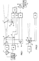
- a semiconductor laser 1 is mounted on a heat sink 2.
- Input power is fed to the laser from an input power control unit 3, via a summing circuit 4 and an amplifier 5.
- the optical beam from the laser 1 is passed through beam splitters 6 and 7, which direct samples of the beam to photodiodes 8 and 9, respectively.
- an optical filter 10 having a positive transmission gradient versus wavelength characteristic. This filter selectively attenuates the sampled beam depending upon the wavelength of the laser emission.
- the output of the photodiode 9 is fed, via a logarithmic amplifier 11, to the positive input of a subtractor amplifier 12.
- the output of the photodiode 8 is fed via a logarithmic amplifier 13 to the negative input of the subtractor amplifer 12.
- the outputs of the photodiodes 8 and 9 have passed through the amplifiers 13 and 11 and are fed to the positive and negative inputs of the amplifier 12, ratiometric changes common to the photodiodes are cancelled out and do not appear at the output of the amplifier 12.
- the output of the amplifier 12 is independent of the intensity of the laser beam.
- the photodiodes 8 and 9 are selected as a matched pair, so that the output of the amplifier 12 is also independent of the spectral characteristics of the photodiodes. The output is, therefore, dependent only upon the emission wavelength of the semi-conductor laser device 1.
- the emission wavelength is dependent upon the operating temperature of the device, and therefore upon the temperature of the heat sink 2.
- the temperature coefficient of a typical device is approximately + 0.4 nm/°K.
- the heat sink temperature is controlled by a heating or cooling element 14 which is energised from an amplifier 15 controlled by a control line 16 from a wavelength control unit 17.
- the voltage on the line 16 is fed to the positive input of a summing circuit 18.
- the voltage is set to give the heat sink temperature corresponding to a required emission wavelength.
- the element 14 may be a heating element comprising a transistor dissipating, say, approximately 1 watt.
- the output of the subtractor amplifier 12 is fed to the negative input of the circuit 18, so that that outout acts as a negative feedback, in opposition to the control voltage on the line 16.
- This feedback loop therefore controls the temperature of the heat sink 2, thereby maintaining the emission wavelength constant, so that wavelength drift is compensated for.
- any change in the output from the photodiode 8 must be due to a change in intensity of the beam.
- the output of the photodiode 8 is fed to an amplifier 19, and the amplified signal is fed to the summing circuit 4 to act as a negative feedback for the amplifier 5, i.e. in opposition to the voltage from the input power control unit 3.
- This feedback loop therefore controls the laser current, keeping the beam intensity constant at a predetermined level.
- the optical intensity of the laser device may decrease during the lifetime of the device. This is compensated for by increasing the drive signal input to the amplifier 5. However, this would also cause an increase in the laser junc- tion/heat sink temperature and hence cause a change in the emission wavelength.
- the control circuit of the present invention will pull the wavelength back to the predetermined value by decreasing the amount of electrical power fed to the element 14 by the amplifier 15. Hence, the temperature of the laser junction will remain at that level required to initiate the given emission wavelength.
- the optical intensity would have to be readjusted to its predetermined level, since the photodiode 8 is spectrally dependent.
- the two photodiodes may advantageously be identical devices formed on the same header.
- the circuit will automatically set the wavelength and intensity of emission of the new device at the same levels as the old device.
- wavelength control is described above in relation to the control of the operating temperature of the laser 1, other operating parameters, such as the application of mechanical pressure or the application of a magnetic field, or any combination of such parameters, may be controlled.
- Fig. 2 shows one example of a modified form of wavelength control for use in the Fig. 1 embodiment.
- the output is fed to a piezoelectric crystal 20.
- a resonant cavity 21 at the output of the laser comprises a lens 22 and an optical grating 23 in the path of the beam.
- the crystal 20 is arranged to set the angle of the grating 23 relative to the axis of the beam, and to vary said angle in dependence upon the voltage applied to the crystal from the amplifier 15. Variation of the angle changes the tuning of the laser and acts as a wavelength control.
- the use of the optical grating also reduces the laser line width from approximately 4 nm to approximately 0.1 nm. This reduction allows a considerable increase in the number of lasers which can be used together in a multiplex system.
Landscapes
- Physics & Mathematics (AREA)
- Electromagnetism (AREA)
- Optics & Photonics (AREA)
- Engineering & Computer Science (AREA)
- Plasma & Fusion (AREA)
- Condensed Matter Physics & Semiconductors (AREA)
- General Physics & Mathematics (AREA)
- Semiconductor Lasers (AREA)
- Optical Communication System (AREA)
Claims (8)
Applications Claiming Priority (2)
| Application Number | Priority Date | Filing Date | Title |
|---|---|---|---|
| GB4457277 | 1977-10-26 | ||
| GB4457277 | 1977-10-26 |
Publications (2)
| Publication Number | Publication Date |
|---|---|
| EP0001714A1 EP0001714A1 (de) | 1979-05-02 |
| EP0001714B1 true EP0001714B1 (de) | 1984-03-21 |
Family
ID=10433917
Family Applications (1)
| Application Number | Title | Priority Date | Filing Date |
|---|---|---|---|
| EP78300529A Expired EP0001714B1 (de) | 1977-10-26 | 1978-10-23 | Steuerapparat für eine Halbleiter-Laservorrichtung |
Country Status (4)
| Country | Link |
|---|---|
| US (1) | US4309671A (de) |
| EP (1) | EP0001714B1 (de) |
| JP (1) | JPS5474386A (de) |
| DE (1) | DE2862391D1 (de) |
Families Citing this family (76)
| Publication number | Priority date | Publication date | Assignee | Title |
|---|---|---|---|---|
| JPS5845195B2 (ja) * | 1979-12-26 | 1983-10-07 | 一郎 鶴見 | ダイオ−ドレ−ザの発光波長制御方式 |
| DE3000657A1 (de) * | 1980-01-10 | 1981-07-16 | Licentia Patent-Verwaltungs-Gmbh, 6000 Frankfurt | Anordnung zur wellenlaengestabilisierung von halbleiterlasern |
| JPS56103551A (en) * | 1980-01-22 | 1981-08-18 | Fujitsu Ltd | Light source control system |
| JPS5783079A (en) * | 1980-11-12 | 1982-05-24 | Sharp Corp | Driving method of semiconductor laser |
| EP0060033A1 (de) * | 1981-02-16 | 1982-09-15 | British Telecommunications | Laser-Lichtquelle |
| JPS57190384A (en) * | 1981-05-20 | 1982-11-22 | Toshiba Corp | Wavelength sweeping laser |
| JPS596585A (ja) * | 1982-07-05 | 1984-01-13 | Ricoh Co Ltd | 半導体レ−ザ出力制御方法 |
| US4450565A (en) * | 1982-08-23 | 1984-05-22 | Bell Telephone Laboratories, Incorporated | Spectrally stabilized laser |
| FR2542511B1 (fr) * | 1983-03-09 | 1986-12-19 | Lecoy Pierre | Procede et dispositif de regulation de la puissance lumineuse de diodes laser |
| SE8401773L (sv) * | 1984-03-30 | 1985-10-01 | Boh Optical Ab | Frekvens- och effektreglering hos laserdioder |
| CA1251845A (en) * | 1984-08-06 | 1989-03-28 | Ian D. Henning | Optical amplification |
| JPS6224125A (ja) * | 1985-07-25 | 1987-02-02 | Chino Corp | 光半導体測定装置 |
| GB8522821D0 (en) * | 1985-09-16 | 1985-10-23 | British Telecomm | Frequency referencing system |
| US4683573A (en) * | 1985-09-24 | 1987-07-28 | Bell Communications Research, Inc. | Temperature stabilization of injection lasers |
| JPH01105268A (ja) * | 1986-04-05 | 1989-04-21 | Ricoh Co Ltd | 情報記録用光ビ−ムの出力安定化方法及び装置 |
| US4792956A (en) * | 1986-05-13 | 1988-12-20 | Litton Systems, Inc. | Laser diode intensity and wavelength control |
| US4733253A (en) * | 1986-07-03 | 1988-03-22 | Xerox Corporation | Apparatus and method for detecting and eliminating diode laser mode hopping |
| US4737798A (en) * | 1986-07-03 | 1988-04-12 | Xerox Corporation | Laser diode mode hopping sensing and control system |
| US4823357A (en) * | 1986-11-10 | 1989-04-18 | The United States Of America As Represented By The Secretary Of The Air Force | Diffraction limited dichroic combiner diode laser |
| DE3885134D1 (de) * | 1987-03-30 | 1993-12-02 | Siemens Ag | Anordnung zur Steuerung oder Regelung einer Emissionswellenlänge und emittierten Leistung eines Halbleiterlasers. |
| US4922480A (en) * | 1987-12-02 | 1990-05-01 | American Telephone And Telegraph Company | Technique for improving the percentage of semiconductor lasers usable with a predetermined wavelength specification |
| DE3744323C2 (de) * | 1987-12-28 | 1999-03-11 | Lambda Physik Forschung | Verfahren und Vorrichtung zum Stabilisieren der Frequenz eines Laserstrahles |
| JPH0797675B2 (ja) * | 1989-03-28 | 1995-10-18 | シャープ株式会社 | 半導体レーザ励起型固体レーザ装置 |
| GB2230912B (en) * | 1989-04-22 | 1993-10-20 | Stc Plc | Optical amplifier gain control |
| SE463952B (sv) * | 1989-10-13 | 1991-02-11 | Hans Martin | Anordning foer att moejliggoera en vaaglaengdsstabilisering av en av en halvledarlaser alstrad och utsaend ljusstraale |
| JPH04349236A (ja) * | 1991-05-27 | 1992-12-03 | Pioneer Electron Corp | 光ピックアップ装置 |
| JP3407893B2 (ja) * | 1991-05-27 | 2003-05-19 | パイオニア株式会社 | 半導体レーザ制御装置 |
| US5440669A (en) * | 1991-07-26 | 1995-08-08 | Accuwave Corporation | Photorefractive systems and methods |
| JPH06509429A (ja) * | 1991-07-26 | 1994-10-20 | アキュウェーブ コーポレーション | 光屈折性システムおよび方法 |
| US5491570A (en) * | 1991-07-26 | 1996-02-13 | Accuwave Corporation | Methods and devices for using photorefractive materials at infrared wavelengths |
| US5691989A (en) * | 1991-07-26 | 1997-11-25 | Accuwave Corporation | Wavelength stabilized laser sources using feedback from volume holograms |
| US5796096A (en) * | 1991-07-26 | 1998-08-18 | Accuwave Corporation | Fabrication and applications of long-lifetime, holographic gratings in photorefractive materials |
| CA2116244A1 (en) * | 1991-08-22 | 1993-03-04 | Roberto Enzo DI BIAGGIO | Medical light treatment apparatus |
| IL107633A0 (en) * | 1992-11-19 | 1994-02-27 | Varian Associates | Self-calibrated laser power meter |
| US5381230A (en) * | 1993-02-12 | 1995-01-10 | Honeywell Inc. | Emission source spectrum stabilizer |
| WO1997005679A1 (en) * | 1995-07-27 | 1997-02-13 | Jds Fitel Inc. | Method and device for wavelength locking |
| JPH109961A (ja) * | 1996-06-21 | 1998-01-16 | Kokusai Denshin Denwa Co Ltd <Kdd> | 光波長監視装置 |
| US5825792A (en) * | 1996-07-11 | 1998-10-20 | Northern Telecom Limited | Wavelength monitoring and control assembly for WDM optical transmission systems |
| JP2989775B2 (ja) * | 1997-01-21 | 1999-12-13 | サンテック株式会社 | レーザ光源の波長安定化装置 |
| US5832014A (en) * | 1997-02-11 | 1998-11-03 | Lucent Technologies Inc. | Wavelength stabilization in tunable semiconductor lasers |
| US5956356A (en) * | 1997-12-08 | 1999-09-21 | Lucent Technologies Inc. | Monitoring wavelength of laser devices |
| JP3197869B2 (ja) * | 1998-03-31 | 2001-08-13 | アンリツ株式会社 | 波長可変レーザ光源装置 |
| JP3317896B2 (ja) * | 1998-04-24 | 2002-08-26 | 日本電気株式会社 | レーザ発振波長監視装置 |
| US6580517B2 (en) | 2000-03-01 | 2003-06-17 | Lambda Physik Ag | Absolute wavelength calibration of lithography laser using multiple element or tandem see through hollow cathode lamp |
| US6160832A (en) | 1998-06-01 | 2000-12-12 | Lambda Physik Gmbh | Method and apparatus for wavelength calibration |
| US7006541B2 (en) * | 1998-06-01 | 2006-02-28 | Lambda Physik Ag | Absolute wavelength calibration of lithography laser using multiple element or tandem see through hollow cathode lamp |
| AU6142399A (en) | 1998-09-11 | 2000-04-03 | New Focus, Inc. | Tunable laser |
| US6331892B1 (en) | 1998-10-16 | 2001-12-18 | New Focus, Inc. | Interferometer for monitoring wavelength in an optical beam |
| CA2362311A1 (en) * | 1999-03-01 | 2000-09-08 | Regents Of The University Of California | A tunable laser source with an integrated wavelength monitor and method of operating same |
| US6853654B2 (en) * | 1999-07-27 | 2005-02-08 | Intel Corporation | Tunable external cavity laser |
| US6879619B1 (en) | 1999-07-27 | 2005-04-12 | Intel Corporation | Method and apparatus for filtering an optical beam |
| EP1218983A1 (de) | 1999-08-10 | 2002-07-03 | Coretek, Inc. | Optische referenzwellenlängen vorrichtung mit einzelnem etalon |
| US6597462B2 (en) | 2000-03-01 | 2003-07-22 | Lambda Physik Ag | Laser wavelength and bandwidth monitor |
| GB2360628A (en) * | 2000-03-25 | 2001-09-26 | Marconi Comm Ltd | A stabilised radiation source |
| EP1158630B1 (de) * | 2000-04-25 | 2006-12-06 | Avanex Corporation | Wellenlängenstabilisierungsvorrichtung und dessen Arbeitswellenlängenjustierungsverfahren |
| US7209498B1 (en) | 2000-05-04 | 2007-04-24 | Intel Corporation | Method and apparatus for tuning a laser |
| US6807205B1 (en) | 2000-07-14 | 2004-10-19 | Lambda Physik Ag | Precise monitor etalon calibration technique |
| US7120176B2 (en) * | 2000-07-27 | 2006-10-10 | Intel Corporation | Wavelength reference apparatus and method |
| US6738140B2 (en) * | 2000-09-19 | 2004-05-18 | Lambda Control, Inc. | Wavelength detector and method of detecting wavelength of an optical signal |
| US6747741B1 (en) | 2000-10-12 | 2004-06-08 | Lambda Physik Ag | Multiple-pass interferometric device |
| US6658031B2 (en) | 2001-07-06 | 2003-12-02 | Intel Corporation | Laser apparatus with active thermal tuning of external cavity |
| US6686586B2 (en) | 2001-03-23 | 2004-02-03 | Metrologic Instruments, Inc. | Diffractive-based laser scanning system employing microcontroller programmed for mode-switching correction in response to binary mode switching signal generation |
| US6724797B2 (en) | 2001-07-06 | 2004-04-20 | Intel Corporation | External cavity laser with selective thermal control |
| US6804278B2 (en) | 2001-07-06 | 2004-10-12 | Intel Corporation | Evaluation and adjustment of laser losses according to voltage across gain medium |
| US6822979B2 (en) | 2001-07-06 | 2004-11-23 | Intel Corporation | External cavity laser with continuous tuning of grid generator |
| US6901088B2 (en) * | 2001-07-06 | 2005-05-31 | Intel Corporation | External cavity laser apparatus with orthogonal tuning of laser wavelength and cavity optical pathlength |
| EP1329998A1 (de) * | 2002-01-21 | 2003-07-23 | Agilent Technologies, Inc. (a Delaware corporation) | Arrangement für Überwachung der Emissionswellenlänge einer Laserquelle |
| US6768096B2 (en) | 2002-01-31 | 2004-07-27 | Digital Optics Corp. | Passive thermal stabilization of wavelength monitor |
| US7230959B2 (en) | 2002-02-22 | 2007-06-12 | Intel Corporation | Tunable laser with magnetically coupled filter |
| EP1345298A1 (de) * | 2002-03-16 | 2003-09-17 | Agilent Technologies, Inc. (a Delaware corporation) | Wellenlängenkontrollgerät und Verfahren dafür |
| DE60216907T2 (de) * | 2002-07-11 | 2007-06-14 | Avago Technologies Fiber Ip (Singapore) Pte. Ltd. | Vorrichtung und Verfahren zur Wellenlängenbestimmung |
| EP1381090A1 (de) * | 2002-07-11 | 2004-01-14 | Agilent Technologies, Inc. - a Delaware corporation - | Vorrichtung und Verfahren zur Wellenlängenmessung |
| US7133136B2 (en) * | 2003-10-22 | 2006-11-07 | Jds Uniphase Corporation | Wavelength monitor |
| US8112243B2 (en) * | 2007-06-20 | 2012-02-07 | The United States Of America As Represented By The Administrator Of The National Aeronautics And Space Administration | Forward voltage short-pulse technique for measuring high power laser array junction temperture |
| DE102017119810B4 (de) * | 2017-08-29 | 2019-05-09 | fos4X GmbH | Optoelektrischer Chip |
| US11391969B2 (en) | 2018-12-07 | 2022-07-19 | Freedom Photonics Llc | Systems and methods for wavelength monitoring |
Family Cites Families (7)
| Publication number | Priority date | Publication date | Assignee | Title |
|---|---|---|---|---|
| US3588738A (en) * | 1968-09-03 | 1971-06-28 | Hughes Aircraft Co | Frequency stabilized laser |
| US3641459A (en) * | 1969-06-16 | 1972-02-08 | Bell Telephone Labor Inc | Apparatus and method for narrowing the pulse width and stabilizing the repetition rate in semiconductor lasers exhibiting self-induced pulsing |
| JPS542553B2 (de) * | 1971-09-20 | 1979-02-08 | ||
| US3835415A (en) * | 1972-06-28 | 1974-09-10 | Ibm | High radiance semiconductor laser |
| FR2263623A1 (en) * | 1974-03-08 | 1975-10-03 | Ibm | Laser resonator with automatic alignment control - has grid-shaped resonator enclosing reflector with refractive maximum as function of wavelength |
| US4019048A (en) * | 1976-03-22 | 1977-04-19 | Bell Telephone Laboratories, Incorporated | Regenerator for an optical transmission system |
| US4009385A (en) * | 1976-03-22 | 1977-02-22 | Bell Telephone Laboratories, Incorporated | Laser control circuit |
-
1978
- 1978-10-23 EP EP78300529A patent/EP0001714B1/de not_active Expired
- 1978-10-23 DE DE7878300529T patent/DE2862391D1/de not_active Expired
- 1978-10-26 JP JP13106978A patent/JPS5474386A/ja active Granted
-
1980
- 1980-12-18 US US06/217,807 patent/US4309671A/en not_active Expired - Lifetime
Also Published As
| Publication number | Publication date |
|---|---|
| EP0001714A1 (de) | 1979-05-02 |
| JPS5474386A (en) | 1979-06-14 |
| US4309671A (en) | 1982-01-05 |
| JPS6412113B2 (de) | 1989-02-28 |
| DE2862391D1 (de) | 1984-04-26 |
Similar Documents
| Publication | Publication Date | Title |
|---|---|---|
| EP0001714B1 (de) | Steuerapparat für eine Halbleiter-Laservorrichtung | |
| US6111688A (en) | Optical amplifier and system including the same | |
| US6862136B2 (en) | Hybrid optical transmitter with electroabsorption modulator and semiconductor optical amplifier | |
| EP0703647B1 (de) | Vorrichtung zur Unterdrückung von stimulierter Brillouin Streuung | |
| US6272157B1 (en) | Apparatus and method for calibrating a wavelength stabilized laser | |
| US8879589B2 (en) | Stabilizing beam pointing of a frequency-converted laser system | |
| US3628173A (en) | Laser mode selection and stabilization apparatus employing a birefringement etalon | |
| US5363385A (en) | Fiber-optic amplifier with control of the pump light wavelength | |
| JPH11238946A (ja) | レーザ・モジュールおよびその波長および光パワーを同時に安定化させる方法 | |
| US5220578A (en) | Long term mode stabilization for distributed bragg reflector laser | |
| US6301280B1 (en) | Apparatus and method for forming a laser control signal, and a laser including the apparatus | |
| EP1269589B1 (de) | Stabilisierte strahlungsquelle | |
| US6965622B1 (en) | Wavelength locking scheme and algorithm for ultra-high density WDM system | |
| JP4336091B2 (ja) | 光モジュール、光送信器及びwdm光送信装置 | |
| US6678293B2 (en) | Wavelength sensitive device for wavelength stabilization | |
| EP0060033A1 (de) | Laser-Lichtquelle | |
| Woodward et al. | Wavelength stabilization of a DBR laser using an in-fiber Bragg filter | |
| JP2694803B2 (ja) | 光半導体レーザ装置の波長安定化方式 | |
| Ueno et al. | Fast wavelength switching with DFB lasers utilizing thermal compensation | |
| US20090141757A1 (en) | Optical amplifiers | |
| US6847664B2 (en) | Optical device with wavelength monitor | |
| US12095228B2 (en) | Tunable laser with active material on at least one end for monitoring performance | |
| JP2017147299A (ja) | 半導体レーザ光源 | |
| JP4605662B2 (ja) | ゲインクランプ型光増幅器 | |
| US6441940B1 (en) | Wavelength stabilization of light emitting components |
Legal Events
| Date | Code | Title | Description |
|---|---|---|---|
| PUAI | Public reference made under article 153(3) epc to a published international application that has entered the european phase |
Free format text: ORIGINAL CODE: 0009012 |
|
| AK | Designated contracting states |
Designated state(s): DE FR NL SE |
|
| 17P | Request for examination filed | ||
| RAP1 | Party data changed (applicant data changed or rights of an application transferred) |
Owner name: THE POST OFFICE |
|
| GRAA | (expected) grant |
Free format text: ORIGINAL CODE: 0009210 |
|
| AK | Designated contracting states |
Designated state(s): DE FR NL SE |
|
| REF | Corresponds to: |
Ref document number: 2862391 Country of ref document: DE Date of ref document: 19840426 |
|
| ET | Fr: translation filed | ||
| PLBE | No opposition filed within time limit |
Free format text: ORIGINAL CODE: 0009261 |
|
| STAA | Information on the status of an ep patent application or granted ep patent |
Free format text: STATUS: NO OPPOSITION FILED WITHIN TIME LIMIT |
|
| 26N | No opposition filed | ||
| REG | Reference to a national code |
Ref country code: FR Ref legal event code: TP |
|
| NLS | Nl: assignments of ep-patents |
Owner name: BRITISH TELECOMMUNICATIONS TE LONDEN, GROOT-BRITTA |
|
| NLS | Nl: assignments of ep-patents |
Owner name: BRITISH TELECOMMUNICATIONS PLC TE LONDEN, GROOT-BR |
|
| EAL | Se: european patent in force in sweden |
Ref document number: 78300529.1 |
|
| PGFP | Annual fee paid to national office [announced via postgrant information from national office to epo] |
Ref country code: FR Payment date: 19970910 Year of fee payment: 20 |
|
| PGFP | Annual fee paid to national office [announced via postgrant information from national office to epo] |
Ref country code: SE Payment date: 19970918 Year of fee payment: 20 |
|
| PGFP | Annual fee paid to national office [announced via postgrant information from national office to epo] |
Ref country code: DE Payment date: 19970922 Year of fee payment: 20 |
|
| PGFP | Annual fee paid to national office [announced via postgrant information from national office to epo] |
Ref country code: NL Payment date: 19970923 Year of fee payment: 20 |
|
| PG25 | Lapsed in a contracting state [announced via postgrant information from national office to epo] |
Ref country code: NL Free format text: LAPSE BECAUSE OF EXPIRATION OF PROTECTION Effective date: 19981023 |
|
| PG25 | Lapsed in a contracting state [announced via postgrant information from national office to epo] |
Ref country code: SE Free format text: LAPSE BECAUSE OF NON-PAYMENT OF DUE FEES Effective date: 19981024 |
|
| NLV7 | Nl: ceased due to reaching the maximum lifetime of a patent |
Effective date: 19981023 |
|
| EUG | Se: european patent has lapsed |
Ref document number: 78300529.1 |