EP0001729A2 - Verfahren und Einrichtung zur Verbesserung des radiologischen Auflösungsvermögens eines röntgendiagnostischen Systems - Google Patents
Verfahren und Einrichtung zur Verbesserung des radiologischen Auflösungsvermögens eines röntgendiagnostischen Systems Download PDFInfo
- Publication number
- EP0001729A2 EP0001729A2 EP78400121A EP78400121A EP0001729A2 EP 0001729 A2 EP0001729 A2 EP 0001729A2 EP 78400121 A EP78400121 A EP 78400121A EP 78400121 A EP78400121 A EP 78400121A EP 0001729 A2 EP0001729 A2 EP 0001729A2
- Authority
- EP
- European Patent Office
- Prior art keywords
- voltage
- bias voltage
- cathode
- value
- tube
- Prior art date
- Legal status (The legal status is an assumption and is not a legal conclusion. Google has not performed a legal analysis and makes no representation as to the accuracy of the status listed.)
- Granted
Links
- 238000000034 method Methods 0.000 title claims abstract description 23
- 238000004804 winding Methods 0.000 claims description 13
- 239000003990 capacitor Substances 0.000 claims description 10
- 230000010287 polarization Effects 0.000 claims description 6
- 230000000737 periodic effect Effects 0.000 claims description 4
- 238000010894 electron beam technology Methods 0.000 abstract description 6
- 238000009826 distribution Methods 0.000 description 15
- 238000002955 isolation Methods 0.000 description 2
- 230000006978 adaptation Effects 0.000 description 1
- 230000008602 contraction Effects 0.000 description 1
- 238000010586 diagram Methods 0.000 description 1
- 238000003908 quality control method Methods 0.000 description 1
- 230000006641 stabilisation Effects 0.000 description 1
- 238000011105 stabilization Methods 0.000 description 1
- 238000009827 uniform distribution Methods 0.000 description 1
Images


Classifications
-
- H—ELECTRICITY
- H05—ELECTRIC TECHNIQUES NOT OTHERWISE PROVIDED FOR
- H05G—X-RAY TECHNIQUE
- H05G1/00—X-ray apparatus involving X-ray tubes; Circuits therefor
- H05G1/08—Electrical details
- H05G1/26—Measuring, controlling or protecting
- H05G1/30—Controlling
- H05G1/52—Target size or shape; Direction of electron beam, e.g. in tubes with one anode and more than one cathode
-
- H—ELECTRICITY
- H01—ELECTRIC ELEMENTS
- H01J—ELECTRIC DISCHARGE TUBES OR DISCHARGE LAMPS
- H01J35/00—X-ray tubes
- H01J35/02—Details
- H01J35/14—Arrangements for concentrating, focusing, or directing the cathode ray
- H01J35/147—Spot size control
Definitions
- the present invention relates to a method and a device for improving radiological quality. or definition of the foci of X-ray tubes.
- the quality of the image in radiology is linked, among other things, to the dimensions of the focal point of the X-ray tube.
- the geometrical blur is all the lower the smaller the focal point.
- the effective dimensions of the focal points can be determined by the pinhole method or by the modulation transfer function (FTM) method of test patterns.
- FTM modulation transfer function
- This second method has the advantage of also giving the electronic distribution at the focal surface.
- the radiological quality of a focus of given nominal dimensions is also linked to the uniformity of this distribution.
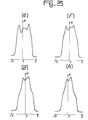
- a microdensitometric section of these radio-images shows on a densitogram two or more peaks and one or more very pronounced valleys, as shown in Figure 1 which represents diagrams of the distribution of incident electrons (N, number of electrons) in a cross section of the focus (X, distance from the focal point axis).
- the dimensions measured by the pinhole method are always smaller than those determined by the FTM of the test patterns.
- this last method is often applied by radiologists for the quality control of the hearths of X tubes.
- manufacturers are obliged to sort the hearths or to replace the tubes until '' to customer satisfaction, resulting in a loss of time, money and reputation for the manufacturer's brand, despite the dimensional compliance of homes with most of the standards in force based on the pinhole method.
- the dimensions of the foci can be reduced by applying a voltage to the concentrating part of the electron beam emitted by the filament constituted by a cup-shaped electrode surrounding the latter on the side opposite that opposite the target (anticathode). of negative polarization Vp.
- Vp negative polarization
- Figure 1 attached gives the width 1 and the electrical distribution tronic of the hearths of the same tube for several values V.
- a fixed target X-ray tube having a cathode of substantially circular shape, indirectly heated and of large dimension (diameter) emitting towards the target, which is of comparable size, a large diameter electron beam.
- the tube is surrounded by a focusing coil which acts on the concentration of the election beam in response to the current flowing through it. The periodic variation of this current causes a contraction and a periodic spreading of the flow of electrons striking the target so as to compensate for irregularities in the beam.
- the X-ray tube also comprises an additional electrode, called a grid, of cylindrical or annular shape, placed approximately halfway between the cathode and the target, and surrounding the electron beam so as to act simultaneously on the concentration of the electron flow and on its intensity. Pulsed modulation of the grid bias voltage therefore acts on the current and the size of the hearth in the opposite direction.
- a set of conventional deflection coils generating orthogonal magnetic fields also makes it possible to scan the target with the electron beam.
- the cathode and the grid. are then equivalent to a rectifier diode, because the anode-cathode voltage is then negative and there is no anode current.
- the grid bias voltage becomes all the more negative as the potential of the anode becomes positive, thus generating a relative stabilization of the current and of the dimensions of the focal point.
- the object of the invention is to remedy the drawbacks of the constant polarization of the 3rd concentration part in a linear filament tube. end constituting the cathode. It allows, while keeping constant the overall dimensions, read in pinhole, to modify the electronic distribution of the focus so that the dimensions determined by the function of the transfer of modulation of test patterns can be adjusted to equal values, smaller or much smaller (up to 50%) than the dimensions determined by the pinhole method.
- the method according to the invention is mainly characterized in that the biasing voltage of the concentrating part is periodically varied between a minimum negative value cu zero and a maximum negative value, with a frequency such that each operating time of the X-ray tube has a large number of periods of variation of the bias voltage.
- the electron beams give rise to bars which can scan the entire focal surface, in order to ensure a substantially uniform electronic distribution to the focus.
- the modulation frequency of the bias voltage is between 20 and 60 kilohertz.
- the invention also relates to a device for implementing the method defined above.
- FIGS. 1 (a) to 1 (e) the densitometric distribution curves of the electrons are shown respectively in the transverse direction of a linear focus, for several values of the DC bias voltage V p of the concentrating part. . It can be seen there that the width l at mid-height of the focal point and the spacing and the number of peaks (bars) vary appreciably as a function of the absolute value of the negative bias voltage.
- Figure 1 (a) gives for a pulp tension V, a width l of 1.45 mm with four peaks (three minima) whose extremes have significant amplitudes.
- Figure 1 (b) gives, for a voltage V p of - 100 V, a width of 1.09 mm with three peaks (two minima) of substantially equal heights.
- Figure 1 (c) has been taken at a polarization voltage V p of - 200 V and it gives a width l of 0.91 mm with three peaks of lesser amplitude.
- Figure 1 (d) gives, for a voltage V p of - 300 V, a width l of 0.78 mm with substantially two peaks of even lower amplitude
- Figure 1 (e) gives, for a voltage V of - 400 V, a width l of 0.65mm with two peaks (maximum) delimiting a median trough (minimum), of reduced amplitudes.
- the method of the invention consists in varying or modulating the bias voltage of the concentrator, negative with respect to the cathode, with a voltage waveform whose frequency is greater than 10 KHz and, preferably between 20 and 60 kHz.
- a voltage waveform whose frequency is greater than 10 KHz and, preferably between 20 and 60 kHz.
- the bias voltage will therefore vary between a minimum or zero negative value and a maximum negative value chosen experimentally.
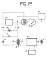
- FIG. 2 shows a method of producing a device for modulating the bias voltage of the concentrator for implementing the method according to the invention. It includes an amplifier 1, one input of which is supplied by the output of a signal generator 2, the amplitude, waveform and frequency of which can be varied, as required.
- the other input of amplifier 1 receiving a continuous supply voltage, variable from a voltage source 13, makes it possible to vary the gain of amplifier 1 in order to adjust the peak-to-peak amplitude from there negative bias voltage of the concentrator.
- the output of the amplifier 1 supplies the primary winding 31 of an isolation transformer 3 which isolates the amplifier 1 from the high-voltage part of the circuit while transmitting to it the AC component of its output signal.
- the secondary winding 32 of the transformer 3 supplies a series circuit composed of a capacitor 4 and a diode 5, the anode of which is joined to one of the capacitor terminals 4 and the cathode of which is connected to one of the terminals of the secondary winding, the other terminal of the capacitor 4 being joined to the other terminal of this winding 32.
- This series arrangement is equivalent to a half-wave peak rectifier which generates across the capacitor 4 a DC voltage substantially equal to the peak value of the AC voltage, with the positive pole at the junction of the capacitor 4 with the winding 32 and the negative pole at its junction with the anode of diode 5.
- the cathode of diode 5 is therefore galvanically connected to the positive pole and its anode to the negative pole.
- This rectified DC voltage is superimposed on the alternating voltage from the amplifier 1, which is transmitted by the capacitor 4 and appears substantially entirely at the terminals A and B of the diode 5.
- the diode 5 also plays the role of a setting diode (known as "clamping" in Anglo-American literature) by making the positive peaks of the waveform coincide with the potential of the positive pole of the capacitor 4, because it only conducts when its anode is positive with respect to at his cathode.
- a setting diode known as "clamping” in Anglo-American literature
- the positive pole B of the variable or modulated negative polarization device is connected to the cathode of the X-ray tube 12, more precisely to the junction C of two filaments 7 and 8 because FIG. 2 shows a tube 12 with two foci.
- the negative pole A of this device is then connected to the conventional concentrating part 6, in the form of a cup which surrounds the filaments 7, 8 on the sides opposite to that opposite the target.
- the concentrating part 6 will then be subjected to a negative bias voltage with respect to the cathode C of the tube which will vary between a zero value and a maximum negative value - V pmax which is equal to the peak-to-peak value of the voltage waveform supplied by the secondary winding, the DC component of this bias voltage then being equal to the average value of the voltage between poles A and B.
- V p of the concentrator may be desirable to vary the bias voltage V p of the concentrator between a minimum negative value - V pmin less than zero and a maximum negative value - V p max .
- This can be obtained by inserting between terminals C (junction of filaments 7 and 8) and B (positive pole of the polarization device) a fixed DC voltage source (not shown) of low internal resistance, joined with its positive pole to the terminal C and with its negative pole at terminal B.
- the peak-to-peak value of the voltage waveform at the bemes of winding 32 must then be equal to (V pmax - V pmin ).
- the filaments 7, 8 are supplied in a conventional manner by a supply 10 which may include an isolation transformer and the adaptation and the anode and the cathode C of the tube 12 are respectively joined to the two poles of a very high supply -variable and controllable voltage with regard to the duration of its operation, called radiological generator.
- a supply 10 which may include an isolation transformer and the adaptation and the anode and the cathode C of the tube 12 are respectively joined to the two poles of a very high supply -variable and controllable voltage with regard to the duration of its operation, called radiological generator.
- the invention is in no way limited to the embodiments described and / or shown.
- the modulation circuit described can be replaced by any other device making it possible to obtain the same output voltage.
Landscapes
- Health & Medical Sciences (AREA)
- General Health & Medical Sciences (AREA)
- Toxicology (AREA)
- X-Ray Techniques (AREA)
- Analysing Materials By The Use Of Radiation (AREA)
Applications Claiming Priority (2)
| Application Number | Priority Date | Filing Date | Title |
|---|---|---|---|
| FR7731743 | 1977-10-21 | ||
| FR7731743A FR2406890A1 (fr) | 1977-10-21 | 1977-10-21 | Procede et dispositif pour ameliorer la definition radiologique des foyers des tubes a rayons x |
Publications (3)
| Publication Number | Publication Date |
|---|---|
| EP0001729A2 true EP0001729A2 (de) | 1979-05-02 |
| EP0001729A3 EP0001729A3 (en) | 1979-08-08 |
| EP0001729B1 EP0001729B1 (de) | 1981-03-25 |
Family
ID=9196804
Family Applications (1)
| Application Number | Title | Priority Date | Filing Date |
|---|---|---|---|
| EP78400121A Expired EP0001729B1 (de) | 1977-10-21 | 1978-09-29 | Verfahren und Einrichtung zur Verbesserung des radiologischen Auflösungsvermögens eines röntgendiagnostischen Systems |
Country Status (7)
| Country | Link |
|---|---|
| US (1) | US4213048A (de) |
| EP (1) | EP0001729B1 (de) |
| JP (1) | JPS5484988A (de) |
| CA (1) | CA1118115A (de) |
| DE (1) | DE2860563D1 (de) |
| FR (1) | FR2406890A1 (de) |
| IT (1) | IT1159940B (de) |
Cited By (2)
| Publication number | Priority date | Publication date | Assignee | Title |
|---|---|---|---|---|
| GB2129233A (en) * | 1982-10-08 | 1984-05-10 | Yokogawa Electric Works Ltd | X-ray computerized tomograph |
| FR2687505A1 (fr) * | 1992-02-13 | 1993-08-20 | Gen Electric Cgr | Circuit de chauffage de filaments de cathode d'un tube a rayons x. |
Families Citing this family (8)
| Publication number | Priority date | Publication date | Assignee | Title |
|---|---|---|---|---|
| US4685118A (en) * | 1983-11-10 | 1987-08-04 | Picker International, Inc. | X-ray tube electron beam switching and biasing method and apparatus |
| US4764947A (en) * | 1985-12-04 | 1988-08-16 | The Machlett Laboratories, Incorporated | Cathode focusing arrangement |
| US5007074A (en) * | 1989-07-25 | 1991-04-09 | Picker International, Inc. | X-ray tube anode focusing by low voltage bias |
| US5535254A (en) * | 1995-05-17 | 1996-07-09 | Carlson; Todd R. | X-ray tube with self-biasing deck |
| DE20218138U1 (de) | 2002-11-21 | 2004-04-08 | Heuft Systemtechnik Gmbh | Röntgenanlage zur Erzeugung von kurzen Röntgenstrahlenimpulsen und mit einer solchen Röntgenanlage arbeitende Inspektionsvorrichtung |
| US8401151B2 (en) * | 2009-12-16 | 2013-03-19 | General Electric Company | X-ray tube for microsecond X-ray intensity switching |
| US9224572B2 (en) | 2012-12-18 | 2015-12-29 | General Electric Company | X-ray tube with adjustable electron beam |
| US9484179B2 (en) | 2012-12-18 | 2016-11-01 | General Electric Company | X-ray tube with adjustable intensity profile |
Family Cites Families (4)
| Publication number | Priority date | Publication date | Assignee | Title |
|---|---|---|---|---|
| US2862107A (en) * | 1951-04-06 | 1958-11-25 | Gen Electric | Means for and method of controlling the generation of x-rays |
| US3691417A (en) * | 1969-09-02 | 1972-09-12 | Watkins Johnson Co | X-ray generating assembly and system |
| US3743836A (en) * | 1972-02-22 | 1973-07-03 | Machlett Lab Inc | X-ray focal spot control system |
| US3992633A (en) * | 1973-09-04 | 1976-11-16 | The Machlett Laboratories, Incorporated | Broad aperture X-ray generator |
-
1977
- 1977-10-21 FR FR7731743A patent/FR2406890A1/fr active Granted
-
1978
- 1978-09-29 DE DE7878400121T patent/DE2860563D1/de not_active Expired
- 1978-09-29 EP EP78400121A patent/EP0001729B1/de not_active Expired
- 1978-10-18 US US05/952,352 patent/US4213048A/en not_active Expired - Lifetime
- 1978-10-18 IT IT28853/78A patent/IT1159940B/it active
- 1978-10-19 CA CA000313778A patent/CA1118115A/fr not_active Expired
- 1978-10-19 JP JP12902478A patent/JPS5484988A/ja active Pending
Cited By (2)
| Publication number | Priority date | Publication date | Assignee | Title |
|---|---|---|---|---|
| GB2129233A (en) * | 1982-10-08 | 1984-05-10 | Yokogawa Electric Works Ltd | X-ray computerized tomograph |
| FR2687505A1 (fr) * | 1992-02-13 | 1993-08-20 | Gen Electric Cgr | Circuit de chauffage de filaments de cathode d'un tube a rayons x. |
Also Published As
| Publication number | Publication date |
|---|---|
| EP0001729B1 (de) | 1981-03-25 |
| DE2860563D1 (en) | 1981-04-16 |
| FR2406890A1 (fr) | 1979-05-18 |
| EP0001729A3 (en) | 1979-08-08 |
| JPS5484988A (en) | 1979-07-06 |
| IT1159940B (it) | 1987-03-04 |
| CA1118115A (fr) | 1982-02-09 |
| IT7828853A0 (it) | 1978-10-18 |
| FR2406890B1 (de) | 1980-09-12 |
| US4213048A (en) | 1980-07-15 |
Similar Documents
| Publication | Publication Date | Title |
|---|---|---|
| US3937959A (en) | Method and apparatus for automatically focusing | |
| EP0001729B1 (de) | Verfahren und Einrichtung zur Verbesserung des radiologischen Auflösungsvermögens eines röntgendiagnostischen Systems | |
| US9035552B2 (en) | Method and device for transporting vacuum arc plasma | |
| RU2019881C1 (ru) | Электронно-лучевая трубка | |
| FR2472800A1 (fr) | Appareil d'affichage a tube a rayons cathodiques | |
| FR2488044A1 (fr) | Dispositif pour detecter des electrons secondaires dans un microscope electronique a balayage | |
| NL8302181A (nl) | Werkwijze en inrichting voor het corrigeren van astigmatisme in een elektronenbundelinrichting. | |
| BE507367A (de) | ||
| GB2217158A (en) | Automatic focusing apparatus for an electron microscope | |
| CN218385119U (zh) | 栅压控制装置和扫描电镜 | |
| FR2665999A1 (fr) | Dispositif d'obtention d'une tension continue reglable. | |
| CH283102A (fr) | Dispositif permettant de faire apparaître, sur une courbe rendue visible sur l'écran d'un tube cathodique, un repère correspondant à une fréquence déterminée. | |
| NL8202499A (nl) | Schakelinrichting voor een beeldweergeefinrichting voor het opwekken van een zaagtandvormige lijnafbuigstroom. | |
| EP0115731A2 (de) | Abtaströntgenröhre | |
| EP0051007B1 (de) | Horizontal- und/oder Vertikalablenkungsvorrichtung mit Korrektur auf einem Bildteil und diese Vorrichtung umfassender Fernsehempfänger | |
| WO2006056833A1 (fr) | Transformateur d’isolation | |
| FR2767016A1 (fr) | Dispositif de production d'energie hyperfrequence comprenant un moyen de conversion de tension | |
| EP0056557A1 (de) | Bildaufnahmeröhre | |
| FR2735282A1 (fr) | Tube a rayons x comportant un capot de polarisation automatique | |
| FR2510306A1 (fr) | Tube analyseur a cible a accumulation et camera comportant un tel tube | |
| JP4545284B2 (ja) | 高圧電源回路 | |
| JPH0261951A (ja) | フィラメント像の振動補正装置を備えた電子顕微鏡 | |
| Nanba et al. | Super-high-sensitive camera tube for HDTV hand-held cameras | |
| BE706124A (de) | ||
| BE413005A (de) |
Legal Events
| Date | Code | Title | Description |
|---|---|---|---|
| PUAI | Public reference made under article 153(3) epc to a published international application that has entered the european phase |
Free format text: ORIGINAL CODE: 0009012 |
|
| AK | Designated contracting states |
Designated state(s): CH DE GB |
|
| PUAL | Search report despatched |
Free format text: ORIGINAL CODE: 0009013 |
|
| AK | Designated contracting states |
Designated state(s): CH DE GB |
|
| 17P | Request for examination filed | ||
| GRAA | (expected) grant |
Free format text: ORIGINAL CODE: 0009210 |
|
| AK | Designated contracting states |
Designated state(s): CH DE GB |
|
| REF | Corresponds to: |
Ref document number: 2860563 Country of ref document: DE Date of ref document: 19810416 |
|
| PGFP | Annual fee paid to national office [announced via postgrant information from national office to epo] |
Ref country code: CH Payment date: 19840813 Year of fee payment: 7 |
|
| PG25 | Lapsed in a contracting state [announced via postgrant information from national office to epo] |
Ref country code: CH Effective date: 19870930 |
|
| REG | Reference to a national code |
Ref country code: CH Ref legal event code: PL |
|
| GBPC | Gb: european patent ceased through non-payment of renewal fee | ||
| PG25 | Lapsed in a contracting state [announced via postgrant information from national office to epo] |
Ref country code: GB Free format text: LAPSE BECAUSE OF NON-PAYMENT OF DUE FEES Effective date: 19881117 |
|
| PGFP | Annual fee paid to national office [announced via postgrant information from national office to epo] |
Ref country code: DE Payment date: 19920825 Year of fee payment: 15 |
|
| PG25 | Lapsed in a contracting state [announced via postgrant information from national office to epo] |
Ref country code: DE Effective date: 19940601 |
|
| PLBE | No opposition filed within time limit |
Free format text: ORIGINAL CODE: 0009261 |
|
| STAA | Information on the status of an ep patent application or granted ep patent |
Free format text: STATUS: NO OPPOSITION FILED WITHIN TIME LIMIT |