EP0001764B1 - Klemmhalter für Wendeschneidplatten - Google Patents
Klemmhalter für Wendeschneidplatten Download PDFInfo
- Publication number
- EP0001764B1 EP0001764B1 EP78101111A EP78101111A EP0001764B1 EP 0001764 B1 EP0001764 B1 EP 0001764B1 EP 78101111 A EP78101111 A EP 78101111A EP 78101111 A EP78101111 A EP 78101111A EP 0001764 B1 EP0001764 B1 EP 0001764B1
- Authority
- EP
- European Patent Office
- Prior art keywords
- clamping
- clamping element
- axis
- insert
- indexable insert
- Prior art date
- Legal status (The legal status is an assumption and is not a legal conclusion. Google has not performed a legal analysis and makes no representation as to the accuracy of the status listed.)
- Expired
Links
- 238000005520 cutting process Methods 0.000 title claims description 4
- 230000002441 reversible effect Effects 0.000 title 1
- 230000001154 acute effect Effects 0.000 claims description 2
- 238000004519 manufacturing process Methods 0.000 description 4
- 230000000694 effects Effects 0.000 description 2
- QNRATNLHPGXHMA-XZHTYLCXSA-N (r)-(6-ethoxyquinolin-4-yl)-[(2s,4s,5r)-5-ethyl-1-azabicyclo[2.2.2]octan-2-yl]methanol;hydrochloride Chemical compound Cl.C([C@H]([C@H](C1)CC)C2)CN1[C@@H]2[C@H](O)C1=CC=NC2=CC=C(OCC)C=C21 QNRATNLHPGXHMA-XZHTYLCXSA-N 0.000 description 1
- 241001494479 Pecora Species 0.000 description 1
- 235000014443 Pyrus communis Nutrition 0.000 description 1
- 230000009194 climbing Effects 0.000 description 1
- 230000003750 conditioning effect Effects 0.000 description 1
- 238000011109 contamination Methods 0.000 description 1
- 230000008878 coupling Effects 0.000 description 1
- 238000010168 coupling process Methods 0.000 description 1
- 238000005859 coupling reaction Methods 0.000 description 1
- 230000007812 deficiency Effects 0.000 description 1
- 238000003754 machining Methods 0.000 description 1
- 238000000034 method Methods 0.000 description 1
- 238000003801 milling Methods 0.000 description 1
- 230000000284 resting effect Effects 0.000 description 1
Images

Classifications
-
- B—PERFORMING OPERATIONS; TRANSPORTING
- B23—MACHINE TOOLS; METAL-WORKING NOT OTHERWISE PROVIDED FOR
- B23B—TURNING; BORING
- B23B27/00—Tools for turning or boring machines; Tools of a similar kind in general; Accessories therefor
- B23B27/14—Cutting tools of which the bits or tips or cutting inserts are of special material
- B23B27/16—Cutting tools of which the bits or tips or cutting inserts are of special material with exchangeable cutting bits or cutting inserts, e.g. able to be clamped
- B23B27/1662—Cutting tools of which the bits or tips or cutting inserts are of special material with exchangeable cutting bits or cutting inserts, e.g. able to be clamped with plate-like cutting inserts clamped against the walls of the recess in the shank by a clamping member acting upon the wall of a hole in the cutting insert
-
- B—PERFORMING OPERATIONS; TRANSPORTING
- B23—MACHINE TOOLS; METAL-WORKING NOT OTHERWISE PROVIDED FOR
- B23B—TURNING; BORING
- B23B2205/00—Fixation of cutting inserts in holders
- B23B2205/04—Fixation screws, bolts or pins of particular form
-
- B—PERFORMING OPERATIONS; TRANSPORTING
- B23—MACHINE TOOLS; METAL-WORKING NOT OTHERWISE PROVIDED FOR
- B23B—TURNING; BORING
- B23B2205/00—Fixation of cutting inserts in holders
- B23B2205/16—Shims
-
- Y—GENERAL TAGGING OF NEW TECHNOLOGICAL DEVELOPMENTS; GENERAL TAGGING OF CROSS-SECTIONAL TECHNOLOGIES SPANNING OVER SEVERAL SECTIONS OF THE IPC; TECHNICAL SUBJECTS COVERED BY FORMER USPC CROSS-REFERENCE ART COLLECTIONS [XRACs] AND DIGESTS
- Y10—TECHNICAL SUBJECTS COVERED BY FORMER USPC
- Y10T—TECHNICAL SUBJECTS COVERED BY FORMER US CLASSIFICATION
- Y10T407/00—Cutters, for shaping
- Y10T407/22—Cutters, for shaping including holder having seat for inserted tool
- Y10T407/2272—Cutters, for shaping including holder having seat for inserted tool with separate means to fasten tool to holder
- Y10T407/2274—Apertured tool
- Y10T407/2276—Apertured tool with means projecting through aperture to force tool laterally against reaction surface
- Y10T407/2278—Tilting clamp element and separate means to tilt same
Definitions
- the invention relates to a tool clamp holder, which has a shaft with a recess for supporting a perforated base plate and a perforated indexable insert, as well as a clamping device which has a cylindrical sleeve with an annular collar at its upper end and a collar in a sheep bore under the recess and a clamping element comprises, which projects with its foot part into the sleeve and with its head part through the underlay plate into the hole of the indexable insert and is supported there and which is held in the sleeve by means of disc springs and can be moved in the axial direction against spring force.
- a large number of clamping systems are known, according to which center hole indexable inserts mounted in a shaft recess are clamped against one or more side walls of the shaft recess by means of a clamping element protruding into the center hole.
- the plate is clamped, for example, by rotating an eccentric bolt or a bolt system consisting of several parts that can be moved relative to one another.
- the indexable insert is clamped by tilting the bolt, for example by means of a toggle lever system.
- Clamping tools operating according to such systems are known to have a number of disadvantages, such as the holders with eccentric bolts, above all the disadvantage of high overall height, the requirement for high precision and the risk of contamination and laying of the hexagon opening in the bolt.
- Brackets with toggle levers are expensive to manufacture and require large dimensions in order to ensure sufficient three-point leverage.
- a sleeve is screwed into a hole in the shaft under the insert. Inside this sleeve there is a bolt which can be tensioned against the position of the sleeve in the axial direction by means of disc springs.
- the indexable insert is clamped via the center hole bolt according to the lever principle, with the center hole bolt resting on one point on the inner wall of the center hole and two points on the screwed-in sleeve.
- the predetermined contact points of the clamping bolt cannot be guaranteed with sufficient certainty for this clamping system, so that an exact clamping of the indexable insert is often not ensured.
- the overall height is comparatively large because the areas of the three-point support and the spring seat are spatially one above the other.
- the present invention therefore has the task of creating a clamp holder system which is structurally simple and therefore comparatively cheap to manufacture.
- the clamping system should be suitable for clamping indexable inserts both in turning tools and in the cutter carrier body.
- inevitable dimensional tolerances of the actual clamping element as well as the recesses and bores in the carrier body and finally also the indexable inserts should at most only have a minor influence on the actual clamping of an indexable insert in individual cases.
- the quality of the clamping should practically only be determined by the manufacturing accuracy of the clamping member itself.
- the center hole clamping should be successful regardless of the operator with the same clamping force.
- the clamping element should enable holder designs for both negative and positive inserts. Due to the low overall height of the clamping element, it should also be possible to use it for holders with small shaft dimensions, for example for turning inside copies.
- the clamping must be sufficiently reliable against twisting or loosening of the insert during the work process.
- the clamp holder for center hole inserts is characterized in that the ring collar of the sleeve is followed by an approximately semicircular sleeve extension in plan view, which protrudes inside the perforated insert into the area adjacent to the cutting edge and has an approximately toroidally curved inner surface, on which the as Ball or truncated cone formed head part of the clamping element in two points, which enclose an angle of about 120 ° with the axis of the clamping element.
- the sleeve extension with a toric curved inner surface is obviously symmetrical to a plane, the plane being formed by the sleeve axis and the normal to the lateral contact surface of the indexable insert on the shaft recess.
- Figure 1 shows a preferred embodiment of the clamp holder according to the invention as a section along the plane of symmetry.
- the version of the clamp holder shown is suitable for holding negative indexable inserts with a square base.
- Figure 2 shows an enlarged section of the clamping member of the above clamping holder in the region of the center hole of the insert as a section along the axis A-A 'in Figure 1.
- the cutting plane is chosen so that the contact points of the head part on the inner surface of the sleeve extension lie in this plane.
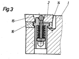
- FIG. 3 shows an embodiment of the inventive tool holder that is suitable for positive indexable inserts, likewise as a section corresponding to FIG. 1.
- the clamp holder according to the invention has a tool shank -1-, a center hole indexable insert -2- together with an underlying base plate -3-.
- the center hole clamping system consists of a sleeve -4- with a snug fit in a shaft bore under the insert.
- the sleeve is secured against twisting by a pin -13-.
- the sleeve has a cover-like sleeve end -5- with a lateral collar.
- the base plate is locked with this collar.
- the sleeve extension -6- starting from the sleeve end extends into the lower region of the center hole of the indexable insert.
- the clamping element designed with disc springs -8- is composed of a pin -7 - passed through the sleeve end, an end piece -9- serving as an abutment for disc springs, for example a locking washer, and a head part -10-.
- the head part can be spherical. But it can also have the shape of a truncated cone or pear shape.
- the replacement and the clamping of the indexable insert is handled as follows:
- the one end of an excentric is through a lateral opening - p out 12 in the bore under the sleeve S by way of the clamping element.
- the clamping element is raised by turning the eccentric key half a turn.
- the head part abuts the center hole wall and the insert can be lifted off.
- the clamping element is lowered by spring force and the indexable insert is clamped again.
- the ball head of the clamping element is always guided along the inner surface of the sleeve extension along the inner surface of the sleeve extension when lowering along two, with respect to the center of the ball approximately at an angle of 120 °, so that the contact of the ball head with the inner wall of the center hole at the predetermined location.
- a slight tilting of the clamping element in the direction of the inner surface of the sleeve extension can be reliably achieved during lifting in that the lateral contact surfaces of the plate springs, namely the sleeve end and the locking washer of the clamping element, are not parallel to one another in the clamping position, but form a corresponding angle.
- the center hole axis In order to be able to use a sleeve of constant wall thickness, the center hole axis must lie in front of the axis of the shaft bore as seen from the sleeve extension.
- Figure 2 illustrates the profile of the inner surface of the sleeve extension serving to support the head part.
- the roughly parabolic section profile in the area of the inner surface between the contact points of the head part is unchanged over a wide range of heights.
- the apex of the curvature of the profile moves with the change in height on a curved curve which can be seen in the sectional view of FIG. 1.
- FIG. 3 shows an embodiment of the inventive clamping holder for positive indexable inserts -14-.
- the center hole of the insert is conical in its upper part -15- intended for the ball head of the clamping element.
- the lower part -16- of the center hole of the indexable insert is advantageously made cylindrical so that the center hole plate can also be used in conventional holder systems.
- the embodiment of the inventive clamp holder according to FIG. 3 also differs from the embodiment according to FIG. 1 in that the sleeve is extended downward beyond the actual clamping elements and that the eccentric key is inserted laterally through a hole in the sleeve to release the clamping system.
- the inventive clamp holder is characterized by simple components.
- the clamping member can therefore advantageously be replaced as a whole quickly and inexpensively.
- the low overall height opens up wide areas of application, for example "for internal machining of workpieces.
- the position of the plates in the clamp holder is always the same regardless of the operator.
- the frictional connection between the insert and the clamping holder shank is fully satisfactory even in cases in which the forces from the workpiece to the insert are to be transmitted in directions that deviate from the ideal direction, namely the resultant of the normal to the anal surfaces.
- the inventive clamp system is therefore suitable for coupling turning.
- the inventive toolholder system is suitable for holding square, but also rhombic and triangular indexable inserts.
- the inventive clamp holder is suitable for holding all commonly used indexable insert sizes.
- the lower limit above which the inventive clamping system becomes too filigree and therefore too expensive for production is therefore not of practical importance.
- the inventive clamp holder can be used both in turning tools and in milling tools.
- the change of the insert is technically and operationally particularly easy and reliable to use. This opens up the possibility of integrating this clamping system into devices for automatic plate changing.
- the clamping element for changing the indexable inserts could be lifted from below through the shaft bore.
Landscapes
- Engineering & Computer Science (AREA)
- Mechanical Engineering (AREA)
- Cutting Tools, Boring Holders, And Turrets (AREA)
Applications Claiming Priority (2)
| Application Number | Priority Date | Filing Date | Title |
|---|---|---|---|
| AT7277/77 | 1977-10-12 | ||
| AT727777A ATA727777A (de) | 1977-10-12 | 1977-10-12 | Werkzeugklemmhalter |
Publications (2)
| Publication Number | Publication Date |
|---|---|
| EP0001764A1 EP0001764A1 (de) | 1979-05-16 |
| EP0001764B1 true EP0001764B1 (de) | 1980-07-23 |
Family
ID=3594436
Family Applications (1)
| Application Number | Title | Priority Date | Filing Date |
|---|---|---|---|
| EP78101111A Expired EP0001764B1 (de) | 1977-10-12 | 1978-10-10 | Klemmhalter für Wendeschneidplatten |
Country Status (5)
| Country | Link |
|---|---|
| US (1) | US4204781A (it) |
| EP (1) | EP0001764B1 (it) |
| AT (2) | ATA727777A (it) |
| DE (1) | DE2860095D1 (it) |
| IT (1) | IT1099367B (it) |
Families Citing this family (12)
| Publication number | Priority date | Publication date | Assignee | Title |
|---|---|---|---|---|
| AT366306B (de) | 1980-04-04 | 1982-04-13 | Plansee Metallwerk | Schneidwerkzeug |
| SE455172B (sv) * | 1984-10-24 | 1988-06-27 | Seco Tools Ab | Skerverktyg med ett elastiskt fjedrande element for fastspenning av ett sker |
| DE10047079A1 (de) * | 2000-09-22 | 2002-04-18 | Kennametal Inc | Zerspanungswerkzeug |
| US7261495B1 (en) * | 2006-02-21 | 2007-08-28 | Kennametal Inc. | Assembly for retaining a cutting insert in a pocket of a tool holder |
| SE530082C2 (sv) * | 2006-05-31 | 2008-02-26 | Seco Tools Ab | Skärverktyg med inrättning för bestämmande av läget hos skär samt förfarande för fixering av ett skär i valbart läge |
| KR101522045B1 (ko) * | 2007-06-06 | 2015-05-20 | 노 스크류 엘티디. | 컷팅 도구 홀더 및 이에 대한 컷팅 인서트 |
| WO2010097797A1 (en) | 2009-02-27 | 2010-09-02 | No Screw Ltd. | Cutting tool, cutting tool holder and cutting insert therefor |
| WO2015033338A2 (en) * | 2013-09-03 | 2015-03-12 | No Screw Ltd. | Mounting mechanism for a cutting insert, a cutting insert therefor and a cutting tool using said insert |
| JP2018504288A (ja) * | 2015-02-04 | 2018-02-15 | ノー スクリュー リミテッド | 切削工具ホルダーおよびそのための切削インサートを備えた切削工具 |
| KR101696534B1 (ko) * | 2015-03-03 | 2017-01-13 | 김종현 | 공작기계용 바이트 홀더장치 |
| EP3288701A1 (en) | 2015-04-30 | 2018-03-07 | No Screw Ltd. | Dynamic clamping mechanism |
| EP3888826A1 (de) * | 2020-03-31 | 2021-10-06 | CERATIZIT Austria Gesellschaft m.b.H. | Zerspanungswerkzeug und verfahren zum indexieren eines schneideinsatzes |
Family Cites Families (7)
| Publication number | Priority date | Publication date | Assignee | Title |
|---|---|---|---|---|
| US3341920A (en) * | 1965-02-16 | 1967-09-19 | Gen Electric | Cutting tool |
| SE333856B (it) * | 1968-07-12 | 1971-03-29 | Sandvikens Jernverks Ab | |
| US3456315A (en) * | 1968-08-15 | 1969-07-22 | Henry W Stier | Cutting tools |
| US3546758A (en) * | 1968-10-02 | 1970-12-15 | Howmet Corp | Cutting tools |
| SE362369B (it) * | 1973-02-21 | 1973-12-10 | Sandvik Ab | |
| DD107222A1 (it) * | 1973-09-21 | 1974-07-20 | ||
| US3996651A (en) * | 1975-09-22 | 1976-12-14 | Kennametal Inc. | Device for holding a cutting insert in the pocket of a tool holder |
-
0
- AT AT727777A patent/AT350875B/de active
-
1977
- 1977-10-12 AT AT727777A patent/ATA727777A/de unknown
-
1978
- 1978-10-10 DE DE7878101111T patent/DE2860095D1/de not_active Expired
- 1978-10-10 EP EP78101111A patent/EP0001764B1/de not_active Expired
- 1978-10-11 US US05/950,376 patent/US4204781A/en not_active Expired - Lifetime
- 1978-10-11 IT IT28632/78A patent/IT1099367B/it active
Also Published As
| Publication number | Publication date |
|---|---|
| IT7828632A0 (it) | 1978-10-11 |
| IT1099367B (it) | 1985-09-18 |
| ATA727777A (de) | 1978-11-15 |
| US4204781A (en) | 1980-05-27 |
| DE2860095D1 (en) | 1980-11-13 |
| EP0001764A1 (de) | 1979-05-16 |
| AT350875B (de) | 1979-06-25 |
Similar Documents
| Publication | Publication Date | Title |
|---|---|---|
| EP0075177B1 (de) | Schneidwerkzeug | |
| DE69303969T2 (de) | Unterlegplatte für Schneidwerkzeug | |
| DE2556098C2 (de) | Vorrichtung zum Einsetzen eines Stiftes in ein Loch eines Werkstückes | |
| DE2652153C2 (it) | ||
| EP0074601A1 (de) | Schneidwerkzeug | |
| DE4444241C2 (de) | Spannvorrichtung | |
| DE69712511T2 (de) | Schneideinsatz sicherungsvorrichtung | |
| DE69604568T2 (de) | Spannvorichtung für schneideinsätze | |
| DE1552308B2 (de) | Auswechselbarer schneideinsatz | |
| EP0001764A1 (de) | Klemmhalter für Wendeschneidplatten | |
| DE69702584T2 (de) | Werkzeughalter für Wendeschneidplatte | |
| DE2826564C2 (de) | Werkzeughalter zur Aufnahme einer Schneidplatte | |
| DE202018100594U1 (de) | Werkzeug für die spanende Bearbeitung | |
| DE4330174A1 (de) | Drehbares Schneidwerkzeug | |
| EP0972613A1 (de) | Mitnahmevorrichtung für eine Werkzeugmaschine | |
| WO1992014569A1 (de) | Kugelausbohrwerkzeug | |
| DE2225747C2 (de) | Schneidwerkzeug für die spanabhebende Bearbeitung | |
| DE1552329A1 (de) | Werkzeughalter fuer spanabhebende Hartmetall-Schneidplaettchen | |
| DE3708363A1 (de) | Spannfutter fuer werkzeugmaschinen | |
| DE2503246C3 (de) | Seitendruckstück für die Werkstückpositionierung | |
| DE4033072A1 (de) | Schneidwerkzeug | |
| DE29514702U1 (de) | Vorrichtung zur Bearbeitung eines Werkstückes, insbesondere einer Wendeschneidplatte | |
| EP0178417A1 (de) | Teilbares Werkzeug für die spanabhebende Bearbeitung | |
| CH673245A5 (it) | ||
| CH446013A (de) | Schnellspannfutter |
Legal Events
| Date | Code | Title | Description |
|---|---|---|---|
| PUAI | Public reference made under article 153(3) epc to a published international application that has entered the european phase |
Free format text: ORIGINAL CODE: 0009012 |
|
| AK | Designated contracting states |
Designated state(s): BE CH DE FR GB NL SE |
|
| 17P | Request for examination filed | ||
| GRAA | (expected) grant |
Free format text: ORIGINAL CODE: 0009210 |
|
| AK | Designated contracting states |
Designated state(s): BE CH DE FR GB NL SE |
|
| REF | Corresponds to: |
Ref document number: 2860095 Country of ref document: DE Date of ref document: 19801113 |
|
| PGFP | Annual fee paid to national office [announced via postgrant information from national office to epo] |
Ref country code: CH Payment date: 19831024 Year of fee payment: 6 |
|
| PGFP | Annual fee paid to national office [announced via postgrant information from national office to epo] |
Ref country code: FR Payment date: 19831025 Year of fee payment: 6 |
|
| PGFP | Annual fee paid to national office [announced via postgrant information from national office to epo] |
Ref country code: DE Payment date: 19831102 Year of fee payment: 6 |
|
| PGFP | Annual fee paid to national office [announced via postgrant information from national office to epo] |
Ref country code: NL Payment date: 19831128 Year of fee payment: 6 |
|
| PGFP | Annual fee paid to national office [announced via postgrant information from national office to epo] |
Ref country code: BE Payment date: 19831130 Year of fee payment: 6 |
|
| PGFP | Annual fee paid to national office [announced via postgrant information from national office to epo] |
Ref country code: SE Payment date: 19840930 Year of fee payment: 7 |
|
| PG25 | Lapsed in a contracting state [announced via postgrant information from national office to epo] |
Ref country code: CH Effective date: 19841031 Ref country code: BE Effective date: 19841031 |
|
| BERE | Be: lapsed |
Owner name: METALLWERK PLANSEE G.M.B.H. Effective date: 19841010 |
|
| PG25 | Lapsed in a contracting state [announced via postgrant information from national office to epo] |
Ref country code: NL Effective date: 19850501 |
|
| GBPC | Gb: european patent ceased through non-payment of renewal fee | ||
| NLV4 | Nl: lapsed or anulled due to non-payment of the annual fee | ||
| PG25 | Lapsed in a contracting state [announced via postgrant information from national office to epo] |
Ref country code: FR Free format text: LAPSE BECAUSE OF NON-PAYMENT OF DUE FEES Effective date: 19850628 |
|
| REG | Reference to a national code |
Ref country code: CH Ref legal event code: PL |
|
| PG25 | Lapsed in a contracting state [announced via postgrant information from national office to epo] |
Ref country code: DE Effective date: 19850702 |
|
| REG | Reference to a national code |
Ref country code: FR Ref legal event code: ST |
|
| PG25 | Lapsed in a contracting state [announced via postgrant information from national office to epo] |
Ref country code: SE Effective date: 19851011 |
|
| PG25 | Lapsed in a contracting state [announced via postgrant information from national office to epo] |
Ref country code: GB Effective date: 19881117 |
|
| EUG | Se: european patent has lapsed |
Ref document number: 78101111.9 Effective date: 19860730 |
|
| PLBE | No opposition filed within time limit |
Free format text: ORIGINAL CODE: 0009261 |
|
| STAA | Information on the status of an ep patent application or granted ep patent |
Free format text: STATUS: NO OPPOSITION FILED WITHIN TIME LIMIT |