EP0001820A1 - Mécanisme d'entraînement de bande, en particulier de bande magnétique - Google Patents
Mécanisme d'entraînement de bande, en particulier de bande magnétique Download PDFInfo
- Publication number
- EP0001820A1 EP0001820A1 EP78101257A EP78101257A EP0001820A1 EP 0001820 A1 EP0001820 A1 EP 0001820A1 EP 78101257 A EP78101257 A EP 78101257A EP 78101257 A EP78101257 A EP 78101257A EP 0001820 A1 EP0001820 A1 EP 0001820A1
- Authority
- EP
- European Patent Office
- Prior art keywords
- roller
- transport according
- tape
- belt transport
- roll
- Prior art date
- Legal status (The legal status is an assumption and is not a legal conclusion. Google has not performed a legal analysis and makes no representation as to the accuracy of the status listed.)
- Granted
Links
- 230000007723 transport mechanism Effects 0.000 title 1
- 230000033001 locomotion Effects 0.000 claims abstract description 41
- 239000000969 carrier Substances 0.000 claims abstract description 33
- 230000008878 coupling Effects 0.000 claims description 18
- 238000010168 coupling process Methods 0.000 claims description 18
- 238000005859 coupling reaction Methods 0.000 claims description 18
- 238000004804 winding Methods 0.000 claims description 18
- 239000004033 plastic Substances 0.000 claims description 14
- 229920003023 plastic Polymers 0.000 claims description 14
- 230000005484 gravity Effects 0.000 claims description 9
- 239000002184 metal Substances 0.000 claims description 5
- 230000001360 synchronised effect Effects 0.000 claims 1
- 238000005096 rolling process Methods 0.000 description 29
- 230000035939 shock Effects 0.000 description 25
- 230000032258 transport Effects 0.000 description 24
- 239000006096 absorbing agent Substances 0.000 description 7
- 230000001133 acceleration Effects 0.000 description 6
- 230000008859 change Effects 0.000 description 6
- 230000000694 effects Effects 0.000 description 5
- 239000007788 liquid Substances 0.000 description 5
- 238000006073 displacement reaction Methods 0.000 description 4
- 239000000463 material Substances 0.000 description 4
- 239000005062 Polybutadiene Substances 0.000 description 3
- 230000008901 benefit Effects 0.000 description 3
- 238000013016 damping Methods 0.000 description 3
- 229920002857 polybutadiene Polymers 0.000 description 3
- 230000035945 sensitivity Effects 0.000 description 3
- 230000009471 action Effects 0.000 description 2
- 239000003921 oil Substances 0.000 description 2
- 230000002093 peripheral effect Effects 0.000 description 2
- 239000011359 shock absorbing material Substances 0.000 description 2
- 229910001209 Low-carbon steel Inorganic materials 0.000 description 1
- 229920005830 Polyurethane Foam Polymers 0.000 description 1
- 229910000639 Spring steel Inorganic materials 0.000 description 1
- 229910000831 Steel Inorganic materials 0.000 description 1
- 230000006978 adaptation Effects 0.000 description 1
- 230000015572 biosynthetic process Effects 0.000 description 1
- 238000010276 construction Methods 0.000 description 1
- 229910052802 copper Inorganic materials 0.000 description 1
- 239000013078 crystal Substances 0.000 description 1
- 238000005520 cutting process Methods 0.000 description 1
- 230000007423 decrease Effects 0.000 description 1
- 230000003247 decreasing effect Effects 0.000 description 1
- 230000001934 delay Effects 0.000 description 1
- 238000011161 development Methods 0.000 description 1
- 230000018109 developmental process Effects 0.000 description 1
- 238000005516 engineering process Methods 0.000 description 1
- 230000002349 favourable effect Effects 0.000 description 1
- 239000010720 hydraulic oil Substances 0.000 description 1
- 230000009191 jumping Effects 0.000 description 1
- 230000005426 magnetic field effect Effects 0.000 description 1
- 230000007257 malfunction Effects 0.000 description 1
- 238000004519 manufacturing process Methods 0.000 description 1
- 238000000034 method Methods 0.000 description 1
- 239000000203 mixture Substances 0.000 description 1
- 238000012986 modification Methods 0.000 description 1
- 230000004048 modification Effects 0.000 description 1
- 229920006327 polystyrene foam Polymers 0.000 description 1
- 239000011496 polyurethane foam Substances 0.000 description 1
- 238000003825 pressing Methods 0.000 description 1
- 230000008569 process Effects 0.000 description 1
- 230000009467 reduction Effects 0.000 description 1
- 239000011435 rock Substances 0.000 description 1
- 239000010959 steel Substances 0.000 description 1
- 125000000391 vinyl group Chemical group [H]C([*])=C([H])[H] 0.000 description 1
- 229920002554 vinyl polymer Polymers 0.000 description 1
Images



Classifications
-
- G—PHYSICS
- G11—INFORMATION STORAGE
- G11B—INFORMATION STORAGE BASED ON RELATIVE MOVEMENT BETWEEN RECORD CARRIER AND TRANSDUCER
- G11B15/00—Driving, starting or stopping record carriers of filamentary or web form; Driving both such record carriers and heads; Guiding such record carriers or containers therefor; Control thereof; Control of operating function
- G11B15/18—Driving; Starting; Stopping; Arrangements for control or regulation thereof
- G11B15/26—Driving record carriers by members acting directly or indirectly thereon
- G11B15/28—Driving record carriers by members acting directly or indirectly thereon through rollers driving by frictional contact with the record carrier, e.g. capstan; Multiple arrangements of capstans or drums coupled to means for controlling the speed of the drive; Multiple capstan systems alternately engageable with record carrier to provide reversal
- G11B15/295—Driving record carriers by members acting directly or indirectly thereon through rollers driving by frictional contact with the record carrier, e.g. capstan; Multiple arrangements of capstans or drums coupled to means for controlling the speed of the drive; Multiple capstan systems alternately engageable with record carrier to provide reversal with single capstan or drum simultaneously driving the record carrier at two separate points of an isolated part thereof, e.g. the capstan acting directly on the tape rollers
Definitions
- the invention relates to a tape transport device, in particular a magnetic tape transport, with winding and unwinding rollers which can be pressed onto the drive roller by means of pressure devices on roller carriers which are movably mounted relative to the drive roller.
- Magnetic tape devices are designed, for example, as such contact winding tape transport devices or tape drives.
- shock absorber device for a magnetic tape cassette in which the tape reels are arranged concentrically one above the other, which prevents the formation of loops and tension in the tape, in particular in the case of jerky, rapid angular accelerations and angular Belt roll delays.
- the shock absorber device works by means of Spring force on both tape reels in such a way that the tape is evenly loaded in accordance with the respective moments of inertia thereof and transport difficulties are avoided.
- a reference to the use of such a shock absorber device for a purpose other than the normal, albeit briefly changing, belt transport is not given and is not suggested.
- shock-sensitive devices for contact winding tape transport. It is known in principle to manufacture or surround the housing of shock-sensitive devices from shock-absorbing material (for example from integral polyurethane foam, polystyrene foam and / or from their shock-absorbing materials). The disadvantage of these measures is that they take up too much space, making them unusable for portable devices.
- shock-sensitive devices within their housing, in particular in the direction of their particular sensitivity to shock by means of shock absorbers, usually rubber-elastic mounts, so that reduced accelerations act on those acting on the housing.
- the task is accomplished with a contact winding tape transport with winding and unwinding rollers that can be pressed onto the drive roller by means of pressure devices on roller carriers that are movably mounted relative to the drive roller.
- a device which on the one hand prevents a rapid relative movement of the roll carriers, but on the other hand allows the slow relative movement of the band rolls necessary for the tape transport by means of the pressure devices.
- the device is a coupling device or locking device which is arranged between the roller carriers.
- rollers themselves are prevented from lifting off the drive roller, so that loops and transport disturbances based thereon are avoided.
- the maximum pressure force of the rollers on the drive roller is also limited to a permissible level. As a result, the belt tension can be maintained to the extent necessary for the transport to function.
- the locking device can be a piston-cylinder device with pressure medium, the piston and cylinder being designed in such a way and the pressure medium being selected in such a way that with slow relative movements of the roller carrier a low movement resistance and with fast relative movements a greater movement resistance is generated by the locking device.
- the locking device can either be arranged parallel to or in series with the pressure devices and in particular be designed as a piston-cylinder device.
- the locking device is an electromagnetic cable roll device, which can consist, for example, of a rotatably mounted cable pulley made of at least partially magnetizable material, which is at least partially supported in the magnetic field of an electromagnet.
- the roller can be arranged to be rotatable and lockable around the plunger of a moving coil electromagnet.
- the locking device can also be a rope-roll device in which the roll is hollow and is filled with plastic with corresponding flow properties.
- the invention relates to a tape transport device and includes a chassis on which the tape drive roller and the tape rollers are rotatable and the two carriers and a pivot axis are pivotally mounted.
- the unwinding and winding rollers are thus pivotally supported by the carrier relative to the drive roller.
- the rollers are pressed against the rotating drive roller by means of a common spring, which also causes them to rotate so that the tape is transferred from the unwind to the take-up roller.
- the carriers pivot appropriately to maintain contact pressure between the rolls and the drive roll.
- Embodiment of the invention in equilibrium with respect to its pivot axis, i.e. their mass, including the tape roll, is distributed such that shock, impact and vibration forces act on the wearer as torque forces of substantially the same magnitude but in the opposite direction.
- the balancing of forces takes place via mass bodies, also referred to as counterweights, which are provided on each carrier and are mounted in such a way that they balance the carrier and the associated band roll with respect to their pivot axis. A uniform pressure force is thus maintained between the tape rolls and the drive roller, even when the device is subjected to strong impact, impact and vibration forces.
- the pivot axis of each carrier is automatically displaceable, so that the carrier remains constantly balanced while the associated tape roll winds up and unwinds becomes.
- the device works in such a way that the current swivel axis is always at least in the vicinity of the center of gravity of the unit consisting of the carrier, the reel and the counterweight.
- the swivel axis displacement is achieved by a rocking device, which essentially consists of two parts, one part of which is arranged on the chassis and the other part on a roller carrier and the parts are at least in a linear contact.
- the contact point can be moved in a region from near the tape roll to near the mass body.
- the parts of the rocking device are expediently designed to prevent slippage and in particular have teeth.
- the parts can be designed as cylinder segments and are in contact with one another via the cylinder surface as contact surfaces.
- At least one tension member can be provided between the bearings of the parts of the rocking device, whereby a pretensioning force can be maintained for constant mutual contact of the parts.
- the mass bodies of the roller carriers can be counterweights, by means of which the roller carriers can be balanced relative to their pivot axis, and devices for displacing the pivot axes can be provided, by means of which the pivot axis of the roller carriers to the center of gravity of the ribbon roller, roller carriers when the mass of the band reels changes and counterweights formed unit is displaceable, so that torques acting on the pivot axis can be at least reduced.
- a displacement of the pivot axis or, seen in plan view, the pivot point is brought about by the rocking device connected to each carrier.
- Each of these rocking devices comprises a support block attached to the chassis and one attached to a support, e.g. skid-shaped, rocking block. Both the support block and the rocking block can be provided with rocking contact surfaces which are in constant contact with one another.
- At least one of the two rocking contact surfaces can be curved, so that the rocking surface of the rocking block can rock on the rocking contact surface of the support block, i.e. the swing contact pads. are in rolling contact with each other.
- the current pivot axis of the carrier i.e. the point at which the two swing surfaces touch can therefore be changed continuously.
- a change in the diameter of a tape roll causes the roll core and therefore the carrier end that carries the roll to be displaced with respect to the drive roll.
- This displacement of the carrier is compensated for in that the rocking block on the support block automatically carries out the rocking movement, as a result of which the pivot axis is shifted, so that both changes in the roll mass and in the roll diameter are automatically compensated for. This ensures the specified contact pressure forces that must be maintained with this type of transport, even in the event of any acceleration forces.
- the invention can also be used with particular success' for contact winding tape devices for the recording and / or reproduction of video signals and in particular of color video signals.
- the space-saving and simple design of the shock-compensating devices also makes it possible to install such a device in a greatly reduced form in a video camera as a so-called camera recorder. It is also advantageous that the practical designs can be operated with a low electrical energy requirement.
- the contact winding tape transport is essentially formed by two magnetic tape rolls, which are arranged as a winding or unwinding roll on movable carriages or swivel arms and the. about opposite to each other to be pressed on a common drive roller.
- Such devices have a preferred direction of shock sensitivity in a common, imaginary plane, which is formed by the three vertical axes of rotation of the two belt rollers and the drive roller. If a thrust acts radially to the belt rollers in this plane, all drive parts are accelerated in the direction of the thrust.
- the inertia of the movable swivel arms with the tape windings counteracts the impact, in such a way that the tape roll lying behind the drive roller in the direction of impact is pressed against the drive roller more strongly (during the impact effect) and the tape roll in front of it is weaker. If the moment of inertia of the tape reel in front of it is large, for example because the entire tape supply is largely on this tape reel at the time of impact, the force of the pressure spring connecting the swivel arms can be overcome and the tape reel in question can be lifted off the drive reel. Without the solution according to the invention, this generally leads to serious operation malfunction if the tape roll lifting off due to impact is just the take-up roll at the same time.
- the drive of the respective roll of tape is briefly interrupted lift the tape output accelerated from the unwinding can no longer be absorbed and the band jumps from the tape guide, so that the tape is transported uncontrollably even after the end of the shock effect until - by From the device is switched off or becomes blocked by tangling the tape.
- the roller carriers in particular the swivel arms in their mutual position, are expediently connected to one another in such a positive and / or non-positive manner or balanced by mass bodies and / or swivel axis displacement in such a way that a lifting of one or both belt rolls from the drive roller is excluded.
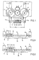
- Figure 1 shows a contact winding drive with two swivel arms 1 and 2, the two rotatably mounted roll cores 3 and 4 with the tape rolls 5 and 6, the spring 9 as a pressure device and the shock-absorbing device according to the invention as a locking device 8.
- the spring 9 pulls the swivel arms 1. and 2 together, whereby the tape rolls 5 and 6 are pressed on the peripheral surface against the central drive roller 7 provided with an elastic support.
- the locking device 8 is pivotally attached with its two end parts to the swivel arms 1 and 2 at the points 10a and 11a, that is to say arranged parallel to the spring 9.
- the locking device 8 essentially consists of two main parts, a cylinder 11 and a piston 10, which are displaceable relative to one another.
- the cylinder space which is not filled in front of piston 10 is filled with a non-compressible medium (pressure medium) which flows from cylinder chamber 12 to cylinder chamber 13 with little resistance when the distance ⁇ L changes slowly, or vice versa, depending on whether the distance ⁇ L decreases or enlarged.
- the piston 10 is selected, for example, somewhat smaller in diameter than the cylinder inner diameter and at Use easily flowing filling medium such as commercially available hydraulic oils on its surface with ring grooves, a so-called labyrinth seal.
- the piston can also be designed to seal the cylinder cross section, in which case a bypass for the pressure medium would have to be provided. So that no liquid emerges from the cylinder chamber 13, the passage of the piston rod through the cylinder housing is provided with a seal 14.
- the length of the piston 10 is preferably 0.5 to 0, g times the length of the cylinder interior.
- shock absorber designs not shown, which are known from hydraulic technology, such as e.g. a piston with a hole or the cylinder bypass already mentioned above applicable.
- Figure 2 shows an advantageous and space-saving combination of the spring 9 with a locking device 36 in a row arrangement.
- the cylinder housing 17 e.g. with an oil filling 20 is attached to one side of a U-shaped frame 15, with the other leg 16, the spring 9 is fixedly connected.
- the spring end of the spring 9 protruding from the leg 16 or the leg 16 itself is rotatably connected to the swivel arm 2.
- the other end of the spring 9 is connected to the piston rod 19 which extends through the cylinder housing 17 on both sides on the side facing the spring.
- the other end of the piston rod 19 is rotatably suspended in the swivel arm 1.
- the passages of the piston rod 19 through the cylinder housing 17 are sealed with seals 14 against leakage of liquid.
- This arrangement ensures that the spring force acts in normal operation via slow movements of the piston 17 as desired on the swivel arms 1 and 2, but when impacted by piston 18, cylinder 17 and frame 15 results in a positive connection of the two swivel arms 1 and 2 , which loosens automatically after the end of the impact.
- FIG. 3 shows a similar arrangement to FIG. 2 with a locking device 37, but with a plastic filling 22 instead of the oil filling in the cylinder housing 17 and a piston 21 which is adapted to the flow properties of the plastic filling 22.
- All plastics come into consideration as the filling 22, which begin to flow even with the slightest but slowly acting loads, but with a fast action (action time ⁇ 0.1 sec), react almost only elastically even with the greatest forces; eg uncrosslinked homopolybutadiene, in an advantageous mixture of 10% 1,2 vinyl polybutadiene, 35% Cu polybutadiene and 55% 1,4 trans polybutadiene.
- Such materials are so viscous that special seals of the cylinder housing 17 at points 23 and 24 are unnecessary.
- the piston 21 is rounded at the edges and its diameter is chosen to be only about half as large as the inside diameter of the cylinder 17.
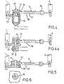
- FIG. 4 shows a further advantageous embodiment of the invention with a locking device 38 combined with the spring 9, again in a row arrangement.
- the spring 9 is movably connected at one end via a connecting part 25 or directly to the swivel arm 2, the other end of the spring 9 is suspended in the eyelet of a rope 26, for example a flexible cord, a steel wire or a plastic cord.
- the rope 26 loops around the roller 27 at least 0.5 to 3.5 times, preferably 1st, 5th times, and is then returned to the connecting part 25 or to the swivel arm 2 and fastened there.
- the roller 27 is rotatably mounted on the holder 29 with an axle pin 28.
- the holder 29 is movably connected to the swivel arm 1.
- an electromagnet for example in the form of a horseshoe, is fastened in such a way that, when the windings of the magnet are traversed by electrical current, the magnet attracts and attracts the roller 27, which consists of magnetizable metal, preferably of soft magnetic metal, for example low-carbon steel prevents a further rotational movement, so that as long as the magnetic field acts, a further expansion of the spring is excluded, since the looping of the roller 27, which is fixed by the magnetic field effect, via the cable part 31 results in a positive locking of the two swivel arms 1 and 2 at a respective distance against one another Increasing the distance ⁇ L results.
- a shock-sensitive sensor element not shown, for example a piezo crystal expediently the magnetic field can only be switched on during a shock.
- FIG. 4a shows an arrangement similar to FIG. 4, with a locking device 3c consisting of a plunger coil 32 and a roller axis formed as a plunger 33.
- a locking device 3c consisting of a plunger coil 32 and a roller axis formed as a plunger 33.
- the force effect of the magnetic holder of the roller 27 described in FIGS. 4 and 4a can also be generated as a pressure medium, as is used in the embodiment in FIG. 3.
- the roller 27 'of the device 40 with a, e.g. annular, cavity 34 provided, which is completely filled with the plastic. This allows slow rotations of the roller 27 'by flowing the plastic.
- the roller 27 ' is blocked against rotation by the friction of the plastic on the walls of the annular cavity 34 and thus the swivel arms 1 and 2 are locked against one another.
- a e.g. radial grooves are attached, which prevents easy sliding of the plastic on the walls.
- the distance between the two tape reel axes changes only slightly when the magnetic tape is passed through from one side to the other when the device is designed appropriately.
- the distance change is max. 1.6 mm and is largest when there is the same amount of tape on both tape rolls.
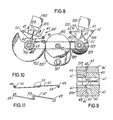
- FIGS. 7 and 8 show a magnetic tape transport system comprising a cylindrical drive roller 111 which is rotatably mounted on a chassis 113 and which a magnetic tape 115 leads past the recording / reproducing magnetic head 117.
- An unwinding roller 119 and a winding roller 121 which are arranged in the same plane as the drive roller, are driven by surface contact pressure between the outermost magnetic tape layer of each tape roll and the elastic peripheral edge of the drive roller.
- the unwinding roll 119 is rotatably mounted on a first swivel arm support 123 and the take-up roll 121 on a second swivel arm support 125.
- the rotatably mounted belt rollers 119 and 121 are pressed onto the drive roller 111 via a garter-like spring 127, which connects the respective supports on pulley parts 129 and 131, as a result of which the contact pressure is applied.
- the two supports 123 and 125 are pivotally mounted on the chassis 113. It is clear that while the tape 115 is being transported from the supply reel 119 past the recording / playback head 117 to the take-up reel 121, the diameters of the tape reels change. Carriers 123 and 124 compensate for these roll diameter changes by freely pivoting in their respective pivot bearings, with the roll cores moving either toward drive roller 111 or away from drive roller 111, thereby maintaining contact pressure between pand rollers and drive roller.
- a counterweight 133 is provided on both the first and on the second carrier 123 or 125 in order to compensate for the weight of the band rolls 119 or 121.
- the carriers are balanced with respect to their respective pivot axes and a uniform contact pressure between belt rollers 119 and 121 and drive roller 111 is maintained, even if the device is subjected to impact, impact or vibration forces in any direction.
- each carrier always coincides with the center of gravity of the entire carrier unit, the latter comprising the carrier, the associated tape roll and the associated counterweight. Since the mass of each band roll changes constantly during operation of the device, the center of gravity of the carrier unit also shifts continuously. Favorable results are achieved if the pivot point always coincides with the center of gravity of the unit.
- Both brackets 123 and 125 are mounted on the chassis 111 via swing units 135 and 137, respectively. Each of these rocking units causes the pivot point of the associated carrier unit to "track" the center of gravity of the unit precisely enough to achieve sufficient damping against impact, shock and vibration.
- Each of the swing units 135 and 137 results in a pivot point for the associated carrier 123 or 125, which is automatically displaceable along a curved path, the local line of possible pivot points, while the associated roller diameter changes.
- the pivot point With the smallest belt roll diameter, ie when the rolls 119 and 121 have their smallest mass, the pivot point has automatically moved to a point which important 133 is closest and farthest from the roll core. It also applies that at maximum tape roll diameter, ie when the roll has its greatest mass, the pivot point automatically moves to a point which is closest to the roll core and is furthest away from the counterweight.
- the carriers 123 and 125 with their tape rolls 119 and 121 and the counterweights 133 are thus constantly balanced or balanced while the tape rolls are being wound up or unwound. If shock or vibration forces act on the transport device, no torque forces are transmitted to the carriers, so that the contact pressure between the belt rollers 119, 121 and the drive roller 111 is essentially not influenced. Essentially constant belt tension and a constant belt transport speed are maintained.
- each of the swing units 135 and 137 comprises a support block 139 which is fastened to the chassis 113, a swing block 41 which is fastened to the associated carrier 123 and 125, and devices for mutually coupling the two blocks 139 and 41.
- the support block 139 has a skid-shaped rolling surface 43, while the swing block has a corresponding skid-shaped swing contact surface 45 which is designed so that it can roll comfortably on the rolling surface 42 of the support block.
- the two swing contact surfaces or skid surfaces 43 and 45 form segments of cylinders with essentially the same radii. They abut one another in such a way that their pivot axes in both cases run parallel to the axes of rotation of the belt rolls 119 and 121.
- the swing block 41 can therefore on the swing block 139 in a plane that extends parallel to that of the drive roller 111 and the belt rollers 119 and 121.
- the respective point at which the two skid surfaces 43 and 45 come into engagement serves as a pivot point for the associated supports 123 and 125, respectively, while the diameter of the associated belt rolls 119 and 121 changes from its largest to its smallest dimension the tape roll core automatically moves relative to the drive roller 111 under the influence of the spring 127.
- This movement causes the rocking block 41 to roll on the support block 139, as a result of which the contact point of the rolling surfaces varies between the surface end closest to the respective tape roll and the surface end closest to the counterweight 133.
- the coupling part for the rocking block 41 and the support block 139 comprises a tension member in the form of a cable 47.
- This coupling prevents the rocking block from being lifted off the support block, but allows a rocking movement on the respective other rolling surface.
- the cable 47 has hooks 49 at both ends.
- One of these hooks 49 is placed around a chassis pin 51, which is located in the center of the curvature of the rolling surface 43 of the support block, while the other hook is placed around a pin 53 on the carrier, which is provided on a lateral extension of the carrier 123 or 125 , in the center of the curvature of the rolling surface-45 of the rocking block.
- the cable 47 extends through coupling slots 55 and 57, which are provided in the support block 139 and in the swing block 41, respectively.
- the assembly of the rocking units 135 and 137 is facilitated by the fact that the central part of the cable 47 is originally designed in such a way that it has an S-shape, the individual bend of which has an angle of approximately 135 °. After the end hooks 49 of the cable 47 are placed around the pins 51 and 53, the S-shape is folded up, so that an elongated 180 ° bend is produced. As a result, the effective length of the cable 47 is shortened, and yet the coupling between the swing block 139 and the support block 41 is achieved by pretensioning, which reliably prevents the two rolling surfaces from lifting apart from one another.
- connection between the swing block 139 and the support block 41 is made with a helical spring which has a hook at each end for looping around the respective pins 51 and 53.
- the tension of this tension spring must be sufficient to ensure that neither shock nor vibration forces can lift the two rolling surfaces apart.
- rocking movement described here can also be achieved by means of rolling surfaces which have numerous curvatures which differ from the skid surfaces of the cylinder segments with the same radius of the exemplary embodiment described.
- the supports 123 and 125 can be balanced even more precisely if the rolling surface 45 of the rocking block has no curvature at all.
- an important advantage can be achieved if the rolling surfaces described in the above exemplary embodiment, that is to say a pair of skid surfaces of cylinder segments with the same radius, are used.
- the rocking unit in this form offers only minimal resistance to the rocking movement of the supports 123 and 125. Since the pins 51 and 53, between which the cable 47 is stretched, are each arranged at the centers of curvature of the rolling surfaces, the force generated by the cable is always aligned with the contact point of the rolling surfaces. As a result, no torque can act on the carrier from the swing unit while the carrier swings through its entire range of motion, and the resistance force that counteracts the rocking movement due to friction is negligible. Since this resistance force is so slight, the pressing force between the belt rollers 119 and 121 and the drive roller 111 can be maintained uniformly.
- a further reduction in the resistance which the rocking unit opposes to the rocking movement of the carrier 123 or 125 is achieved in that the pins 51 and 53 are provided with cutting edges (FIG. 10) for supporting the hooks 49 at the ends of the cable 47.
- the hooks can pivot around the pins instead of sliding along them, which reduces the friction and accordingly reduces the resistance of the rocking unit to the rocking movement caused by the wearer.
- each of the swing units 123 and 125 also includes means for preventing relative slippage between the respective swing contact surfaces 43 and 45.
- the tooth segments are curved, the radius of curvature being the same as that of the rolling surface 43 of the support block, and are on the support block 139 along the Edges of its rolling surfaces provided.
- the toothed segments of the rocking block are also curved and extend on the rocking block 41 along the edges of its rolling surface 45.
- Each sector gear 61 engages with the corresponding toothed segment 63, whereby each sliding movement of the Schau- elblocks k 41 relative to the support block 139 in a direction which is parallel to the plane of movement of the wearer is prevented.
- the engagement of the toothed segments prevents any rocking movement of the carrier about the axis of the cable 47, which connects the rocking block to the support block.
- the engagement of the toothed segments in no way prevents the normal, operational rocking movement of the rocking block on the support block.
- This arrangement includes a pair of cranked springs 65 that extend along the rocking surface 45 of the rocker block, near the coupling slot 57, and a pair of appropriately shaped grooves 67 that similarly extend along the rolling surface 43 of the pad near the edges of its coupling slot 55 .
- Each of the springs 65 engages with the corresponding groove 67. To cause a relative sliding movement between the rolling surfaces 43 and 45 in directions which are to the plane of the view vertical movement of the wearer to prevent.
- the upper sections of the springs preferably do not come into engagement with the lower sections of the corresponding grooves, so that essentially the entire pressure force between the rocking block 41 and the support block 139 can act on the corresponding rolling surfaces.
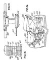
- Figures 14 and 15 show another embodiment of the swing unit 135 or 137, wherein relative sliding movements in any direction four Kop p elb sections be prevented 69 which the bearing block 139 connected to the swing block 41st
- These bands are thin enough in cross section to be easily bent in use, but are relatively stiff in the longitudinal direction and can be made of spring steel or a similar material. Two of these bands extend parallel along the rolling surface 43 of the support block, from the end closest to the counterweight 133 to the point at which the two rolling surfaces are in contact, and further along the rolling surface 45 of the rocking block up to that from the counterweight on farthest end.
- the other two bands extend parallel along the rolling surface 45 of the rocking block, from the end closest to the counterweight to the contact point of the two rolling surfaces, and further along the rolling surface 43 of the support block to the end furthest from the counterweight.
- the two ends of each band are attached to the support block 139 and the swing block 41 at locations outside of the respective rolling surfaces.
- coupling straps 69 described here allows the rocking block 41 to move relative to the support block 139 only as long as the distance between the respective ends of each strap does not increase. This limitation limits the relative movement to the prescribed rocking movement and excludes all other forms of relative movement.
- the examples of the devices according to the invention can also be used for contact winding tape transports with slides as roller carriers in order to achieve the same advantages.
- a tape drive designed with swivel arms with devices of the type described has been tested and optimized in practice so that it can withstand a shock corresponding to an instantaneous acceleration of 40-50 g without interference and damage.
Landscapes
- Advancing Webs (AREA)
- Registering, Tensioning, Guiding Webs, And Rollers Therefor (AREA)
- Devices For Conveying Motion By Means Of Endless Flexible Members (AREA)
- Storing, Repeated Paying-Out, And Re-Storing Of Elongated Articles (AREA)
Applications Claiming Priority (4)
| Application Number | Priority Date | Filing Date | Title |
|---|---|---|---|
| DE2749735 | 1977-11-07 | ||
| DE19772749735 DE2749735A1 (de) | 1977-11-07 | 1977-11-07 | Kontaktwickel-bandtransport |
| US05/852,330 US4147315A (en) | 1977-11-17 | 1977-11-17 | Tape transport apparatus |
| US852330 | 1992-03-24 |
Publications (2)
| Publication Number | Publication Date |
|---|---|
| EP0001820A1 true EP0001820A1 (fr) | 1979-05-16 |
| EP0001820B1 EP0001820B1 (fr) | 1982-10-20 |
Family
ID=25773040
Family Applications (1)
| Application Number | Title | Priority Date | Filing Date |
|---|---|---|---|
| EP78101257A Expired EP0001820B1 (fr) | 1977-11-07 | 1978-10-28 | Mécanisme d'entraînement de bande, en particulier de bande magnétique |
Country Status (11)
| Country | Link |
|---|---|
| EP (1) | EP0001820B1 (fr) |
| JP (1) | JPS5491203A (fr) |
| AT (1) | AT357785B (fr) |
| AU (1) | AU4105578A (fr) |
| CS (1) | CS207673B2 (fr) |
| DD (1) | DD139905A5 (fr) |
| DE (1) | DE2862065D1 (fr) |
| DK (1) | DK494278A (fr) |
| ES (1) | ES474838A1 (fr) |
| IT (1) | IT1100699B (fr) |
| PT (1) | PT68740A (fr) |
Cited By (1)
| Publication number | Priority date | Publication date | Assignee | Title |
|---|---|---|---|---|
| EP0039423A1 (fr) * | 1980-05-07 | 1981-11-11 | BASF Aktiengesellschaft | Dispositif transporteur de bande basé sur le principe du contact par enroulement |
Families Citing this family (1)
| Publication number | Priority date | Publication date | Assignee | Title |
|---|---|---|---|---|
| JPS55130441A (en) * | 1979-03-28 | 1980-10-09 | Fuji Senko Kk | Take-up and rewind apparatus |
Citations (8)
| Publication number | Priority date | Publication date | Assignee | Title |
|---|---|---|---|---|
| US3593945A (en) * | 1968-05-01 | 1971-07-20 | Mennesota Mining And Mfg Co | Capstan assembly |
| DE2107326A1 (de) * | 1970-02-16 | 1971-09-02 | RCA Corp , New York, NY (V St A ) | Viskose Dämpfungsvorrichtung |
| DE2013680A1 (de) * | 1970-03-21 | 1971-09-30 | Siemens Ag | Magnettongerat für perforierte band förmige Aufzeichnungsträger |
| DE2113006A1 (de) * | 1970-03-19 | 1971-10-21 | Nat Res Dev | Stossuebertragungseinheit |
| US3802644A (en) * | 1971-10-01 | 1974-04-09 | Motorola Inc | Differential belt web transport |
| DE2536067A1 (de) * | 1974-08-19 | 1976-03-04 | Basf Ag | Magnetbandtransport mit automatischer bandeinfaedelung |
| DE1574495B2 (de) * | 1968-01-11 | 1976-09-23 | Echo Science Corp. (N.D.Ges.D.Staates Californien), Mountain View, Calif. (V.St.A.) | Bandlaufwerk |
| DE2703806A1 (de) * | 1976-02-02 | 1977-08-04 | American Videonetics Corp | Bandtransporteinrichtung mit differentialandruckkraftsystem |
-
1978
- 1978-10-25 AU AU41055/78A patent/AU4105578A/en active Pending
- 1978-10-28 DE DE7878101257T patent/DE2862065D1/de not_active Expired
- 1978-10-28 EP EP78101257A patent/EP0001820B1/fr not_active Expired
- 1978-11-02 PT PT68740A patent/PT68740A/fr unknown
- 1978-11-03 CS CS787189A patent/CS207673B2/cs unknown
- 1978-11-03 DD DD78208871A patent/DD139905A5/de unknown
- 1978-11-06 ES ES474838A patent/ES474838A1/es not_active Expired
- 1978-11-06 JP JP13592078A patent/JPS5491203A/ja active Pending
- 1978-11-06 AT AT791278A patent/AT357785B/de not_active IP Right Cessation
- 1978-11-06 IT IT29483/78A patent/IT1100699B/it active
- 1978-11-06 DK DK494278A patent/DK494278A/da unknown
Patent Citations (8)
| Publication number | Priority date | Publication date | Assignee | Title |
|---|---|---|---|---|
| DE1574495B2 (de) * | 1968-01-11 | 1976-09-23 | Echo Science Corp. (N.D.Ges.D.Staates Californien), Mountain View, Calif. (V.St.A.) | Bandlaufwerk |
| US3593945A (en) * | 1968-05-01 | 1971-07-20 | Mennesota Mining And Mfg Co | Capstan assembly |
| DE2107326A1 (de) * | 1970-02-16 | 1971-09-02 | RCA Corp , New York, NY (V St A ) | Viskose Dämpfungsvorrichtung |
| DE2113006A1 (de) * | 1970-03-19 | 1971-10-21 | Nat Res Dev | Stossuebertragungseinheit |
| DE2013680A1 (de) * | 1970-03-21 | 1971-09-30 | Siemens Ag | Magnettongerat für perforierte band förmige Aufzeichnungsträger |
| US3802644A (en) * | 1971-10-01 | 1974-04-09 | Motorola Inc | Differential belt web transport |
| DE2536067A1 (de) * | 1974-08-19 | 1976-03-04 | Basf Ag | Magnetbandtransport mit automatischer bandeinfaedelung |
| DE2703806A1 (de) * | 1976-02-02 | 1977-08-04 | American Videonetics Corp | Bandtransporteinrichtung mit differentialandruckkraftsystem |
Cited By (1)
| Publication number | Priority date | Publication date | Assignee | Title |
|---|---|---|---|---|
| EP0039423A1 (fr) * | 1980-05-07 | 1981-11-11 | BASF Aktiengesellschaft | Dispositif transporteur de bande basé sur le principe du contact par enroulement |
Also Published As
| Publication number | Publication date |
|---|---|
| DE2862065D1 (en) | 1982-11-25 |
| AT357785B (de) | 1980-07-25 |
| CS207673B2 (en) | 1981-08-31 |
| IT1100699B (it) | 1985-09-28 |
| ATA791278A (de) | 1979-12-15 |
| DD139905A5 (de) | 1980-01-23 |
| PT68740A (fr) | 1978-12-01 |
| JPS5491203A (en) | 1979-07-19 |
| EP0001820B1 (fr) | 1982-10-20 |
| DK494278A (da) | 1979-05-08 |
| ES474838A1 (es) | 1979-03-16 |
| AU4105578A (en) | 1980-05-01 |
| IT7829483A0 (it) | 1978-11-06 |
Similar Documents
| Publication | Publication Date | Title |
|---|---|---|
| DE2230281C3 (fr) | ||
| DE2341364A1 (de) | Bandantriebssystem | |
| DE1449728A1 (de) | Anordnung zum Umspulen eines Bandes od.dgl. | |
| EP0090164A2 (fr) | Dispositif d'enroulage pour cassette à ruban de machine à écrire | |
| DE7235754U (de) | Antrieb fuer einen bandtransport | |
| DE69816984T2 (de) | Wickelmaschine mit doppelten hilfeinheiten | |
| DE2816699C3 (de) | Einrichtung zur Konstanthaltung des Bandzugs für Aufnahme- und Wiedergabegeräte | |
| DE1956807A1 (de) | Vorrichtung zum Bandtransport | |
| DE2649555C3 (de) | Friktionsantriebsvorrichtung | |
| EP0001820B1 (fr) | Mécanisme d'entraînement de bande, en particulier de bande magnétique | |
| EP0987589A1 (fr) | Dispositif de centrage pour une bobine de matériau photographique | |
| DE1087822B (de) | Laufwerk fuer auf- und abwickelbare Aufzeichnungstraeger mit umschaltbarem Zwischengetriebe | |
| EP0039423B1 (fr) | Dispositif transporteur de bande basé sur le principe du contact par enroulement | |
| DE2749735A1 (de) | Kontaktwickel-bandtransport | |
| CH615647A5 (en) | Thread-tension compensator | |
| DE3151192A1 (de) | Bandkassettengeraet | |
| EP0246694A2 (fr) | Appareil d'enregistrement et/ou de reproduction | |
| DE3025536C2 (de) | Magnetbandkassette | |
| DE737307C (de) | Fuehrungsvorrichtung zum Aufwickeln von Faeden, Draehten, Kabeln, Ketten o. dgl. auf umlaufende Spulen oder Trommeln | |
| DE1905325C3 (de) | Bandtransporteinrichtung | |
| DE3002035A1 (de) | Vorrichtung zum aufspulen eines fadens | |
| DE1809086C3 (de) | Bandtransporteinrichtung | |
| DE2342669C2 (de) | Bandkassette für Endlosband | |
| DE1574495C3 (de) | Bandlaufwerk | |
| DE7734156U1 (de) | Kontaktwickel-bandtransport |
Legal Events
| Date | Code | Title | Description |
|---|---|---|---|
| PUAI | Public reference made under article 153(3) epc to a published international application that has entered the european phase |
Free format text: ORIGINAL CODE: 0009012 |
|
| AK | Designated contracting states |
Designated state(s): BE CH DE FR GB LU NL SE |
|
| 17P | Request for examination filed | ||
| GRAA | (expected) grant |
Free format text: ORIGINAL CODE: 0009210 |
|
| AK | Designated contracting states |
Designated state(s): BE CH DE FR GB LU NL SE |
|
| PG25 | Lapsed in a contracting state [announced via postgrant information from national office to epo] |
Ref country code: SE Effective date: 19821020 Ref country code: CH Effective date: 19821020 Ref country code: BE Effective date: 19821020 |
|
| PG25 | Lapsed in a contracting state [announced via postgrant information from national office to epo] |
Ref country code: LU Free format text: LAPSE BECAUSE OF NON-PAYMENT OF DUE FEES Effective date: 19821031 |
|
| REF | Corresponds to: |
Ref document number: 2862065 Country of ref document: DE Date of ref document: 19821125 |
|
| PGFP | Annual fee paid to national office [announced via postgrant information from national office to epo] |
Ref country code: CH Payment date: 19821231 Year of fee payment: 5 |
|
| ET | Fr: translation filed | ||
| REG | Reference to a national code |
Ref country code: CH Ref legal event code: PL |
|
| PGFP | Annual fee paid to national office [announced via postgrant information from national office to epo] |
Ref country code: FR Payment date: 19840924 Year of fee payment: 7 |
|
| PGFP | Annual fee paid to national office [announced via postgrant information from national office to epo] |
Ref country code: DE Payment date: 19840926 Year of fee payment: 7 |
|
| PGFP | Annual fee paid to national office [announced via postgrant information from national office to epo] |
Ref country code: NL Payment date: 19851031 Year of fee payment: 8 |
|
| PG25 | Lapsed in a contracting state [announced via postgrant information from national office to epo] |
Ref country code: DE Effective date: 19861016 |
|
| PG25 | Lapsed in a contracting state [announced via postgrant information from national office to epo] |
Ref country code: NL Effective date: 19870501 |
|
| NLV4 | Nl: lapsed or anulled due to non-payment of the annual fee | ||
| PG25 | Lapsed in a contracting state [announced via postgrant information from national office to epo] |
Ref country code: FR Free format text: LAPSE BECAUSE OF NON-PAYMENT OF DUE FEES Effective date: 19870630 |
|
| GBPC | Gb: european patent ceased through non-payment of renewal fee | ||
| REG | Reference to a national code |
Ref country code: FR Ref legal event code: ST |
|
| PG25 | Lapsed in a contracting state [announced via postgrant information from national office to epo] |
Ref country code: GB Effective date: 19881117 |
|
| PLBE | No opposition filed within time limit |
Free format text: ORIGINAL CODE: 0009261 |
|
| STAA | Information on the status of an ep patent application or granted ep patent |
Free format text: STATUS: NO OPPOSITION FILED WITHIN TIME LIMIT |