EP0001941A1 - Aus mehreren Schichten übereinander gestapelter Ladeeinheiten bestehende Ladung, sowie Verfahren und Maschine zu deren Ausführung - Google Patents
Aus mehreren Schichten übereinander gestapelter Ladeeinheiten bestehende Ladung, sowie Verfahren und Maschine zu deren Ausführung Download PDFInfo
- Publication number
- EP0001941A1 EP0001941A1 EP78400138A EP78400138A EP0001941A1 EP 0001941 A1 EP0001941 A1 EP 0001941A1 EP 78400138 A EP78400138 A EP 78400138A EP 78400138 A EP78400138 A EP 78400138A EP 0001941 A1 EP0001941 A1 EP 0001941A1
- Authority
- EP
- European Patent Office
- Prior art keywords
- base layer
- burden
- link
- conveyor
- layers
- Prior art date
- Legal status (The legal status is an assumption and is not a legal conclusion. Google has not performed a legal analysis and makes no representation as to the accuracy of the status listed.)
- Granted
Links
- 238000000034 method Methods 0.000 title claims 2
- 238000004519 manufacturing process Methods 0.000 claims description 2
- 230000000694 effects Effects 0.000 description 3
- 239000000463 material Substances 0.000 description 3
- TVEXGJYMHHTVKP-UHFFFAOYSA-N 6-oxabicyclo[3.2.1]oct-3-en-7-one Chemical compound C1C2C(=O)OC1C=CC2 TVEXGJYMHHTVKP-UHFFFAOYSA-N 0.000 description 2
- 230000005484 gravity Effects 0.000 description 2
- 239000013590 bulk material Substances 0.000 description 1
- 229920002457 flexible plastic Polymers 0.000 description 1
- 230000004048 modification Effects 0.000 description 1
- 238000012986 modification Methods 0.000 description 1
- 238000004806 packaging method and process Methods 0.000 description 1
- 229920003023 plastic Polymers 0.000 description 1
- 230000000717 retained effect Effects 0.000 description 1
Images


Classifications
-
- B—PERFORMING OPERATIONS; TRANSPORTING
- B65—CONVEYING; PACKING; STORING; HANDLING THIN OR FILAMENTARY MATERIAL
- B65B—MACHINES, APPARATUS OR DEVICES FOR, OR METHODS OF, PACKAGING ARTICLES OR MATERIALS; UNPACKING
- B65B27/00—Bundling particular articles presenting special problems using string, wire, or narrow tape or band; Baling fibrous material, e.g. peat, not otherwise provided for
-
- B—PERFORMING OPERATIONS; TRANSPORTING
- B65—CONVEYING; PACKING; STORING; HANDLING THIN OR FILAMENTARY MATERIAL
- B65D—CONTAINERS FOR STORAGE OR TRANSPORT OF ARTICLES OR MATERIALS, e.g. BAGS, BARRELS, BOTTLES, BOXES, CANS, CARTONS, CRATES, DRUMS, JARS, TANKS, HOPPERS, FORWARDING CONTAINERS; ACCESSORIES, CLOSURES, OR FITTINGS THEREFOR; PACKAGING ELEMENTS; PACKAGES
- B65D71/00—Bundles of articles held together by packaging elements for convenience of storage or transport, e.g. portable segregating carrier for plural receptacles such as beer cans or pop bottles; Bales of material
-
- B—PERFORMING OPERATIONS; TRANSPORTING
- B65—CONVEYING; PACKING; STORING; HANDLING THIN OR FILAMENTARY MATERIAL
- B65D—CONTAINERS FOR STORAGE OR TRANSPORT OF ARTICLES OR MATERIALS, e.g. BAGS, BARRELS, BOTTLES, BOXES, CANS, CARTONS, CRATES, DRUMS, JARS, TANKS, HOPPERS, FORWARDING CONTAINERS; ACCESSORIES, CLOSURES, OR FITTINGS THEREFOR; PACKAGING ELEMENTS; PACKAGES
- B65D71/00—Bundles of articles held together by packaging elements for convenience of storage or transport, e.g. portable segregating carrier for plural receptacles such as beer cans or pop bottles; Bales of material
- B65D71/0088—Palletisable loads, i.e. loads intended to be transported by means of a fork-lift truck
-
- B—PERFORMING OPERATIONS; TRANSPORTING
- B65—CONVEYING; PACKING; STORING; HANDLING THIN OR FILAMENTARY MATERIAL
- B65D—CONTAINERS FOR STORAGE OR TRANSPORT OF ARTICLES OR MATERIALS, e.g. BAGS, BARRELS, BOTTLES, BOXES, CANS, CARTONS, CRATES, DRUMS, JARS, TANKS, HOPPERS, FORWARDING CONTAINERS; ACCESSORIES, CLOSURES, OR FITTINGS THEREFOR; PACKAGING ELEMENTS; PACKAGES
- B65D2571/00—Bundles of articles held together by packaging elements for convenience of storage or transport, e.g. portable segregating carrier for plural receptacles such as beer cans, pop bottles; Bales of material
- B65D2571/00006—Palletisable loads, i.e. loads intended to be transported by means of a fork-lift truck
- B65D2571/00061—Special configuration of the stack
-
- B—PERFORMING OPERATIONS; TRANSPORTING
- B65—CONVEYING; PACKING; STORING; HANDLING THIN OR FILAMENTARY MATERIAL
- B65D—CONTAINERS FOR STORAGE OR TRANSPORT OF ARTICLES OR MATERIALS, e.g. BAGS, BARRELS, BOTTLES, BOXES, CANS, CARTONS, CRATES, DRUMS, JARS, TANKS, HOPPERS, FORWARDING CONTAINERS; ACCESSORIES, CLOSURES, OR FITTINGS THEREFOR; PACKAGING ELEMENTS; PACKAGES
- B65D2571/00—Bundles of articles held together by packaging elements for convenience of storage or transport, e.g. portable segregating carrier for plural receptacles such as beer cans, pop bottles; Bales of material
- B65D2571/00006—Palletisable loads, i.e. loads intended to be transported by means of a fork-lift truck
- B65D2571/0008—Load supporting elements
- B65D2571/00092—Load supporting elements formed by specially placed articles or parts thereof
-
- B—PERFORMING OPERATIONS; TRANSPORTING
- B65—CONVEYING; PACKING; STORING; HANDLING THIN OR FILAMENTARY MATERIAL
- B65D—CONTAINERS FOR STORAGE OR TRANSPORT OF ARTICLES OR MATERIALS, e.g. BAGS, BARRELS, BOTTLES, BOXES, CANS, CARTONS, CRATES, DRUMS, JARS, TANKS, HOPPERS, FORWARDING CONTAINERS; ACCESSORIES, CLOSURES, OR FITTINGS THEREFOR; PACKAGING ELEMENTS; PACKAGES
- B65D2571/00—Bundles of articles held together by packaging elements for convenience of storage or transport, e.g. portable segregating carrier for plural receptacles such as beer cans, pop bottles; Bales of material
- B65D2571/00006—Palletisable loads, i.e. loads intended to be transported by means of a fork-lift truck
- B65D2571/00111—Arrangements of flexible binders
Definitions
- the present invention relates to the field of handling and it relates more particularly to a burden of the type comprising several superimposed layers of unit charges and at least one link surrounding all of the layers.
- the present invention is particularly, but not exclusively, applicable to burdens whose unit loads consist of bags. filled with bulk material. Frequently, such unit charges must be stored in large quantities in warehouses before being distributed and used.
- the bags are transported by trucks or wagons to the warehouse where they are unloaded and grouped into bundles each comprising several superimposed layers of bags, which are surrounded by at least one link.
- Each bundle thus made is then taken up and transported by a forklift truck to the place of storage where the burdens are placed one beside the other and one on the other so as to form a stack comprising several contiguous "walls" , each wall itself comprising several contiguous columns of burdens.
- the loads are handled using a pallet or a specialized gripping system.
- the main object of the present invention is to remedy these drawbacks by providing a load having a structure such that it is possible to produce load columns having great stability and great height, and this without the use of pallets.
- the burden according to the present invention is characterized in that there is provided in the base layer at least one free space which has a predetermined width and an elongated shape in a direction parallel to the axis of the formed loop by the link and which is overlapped transversely by said link.
- Such a burden can be achieved by arranging the unit loads of the base layer so as to provide therein at leastm free space having a predetermined width and an elongated shape in a predetermined direction, and by surrounding all of the layers with a link having a relatively low tension by forming with the link a loop whose axis is parallel to said predetermined direction.
- the number of free spaces and their location in the base layer depends on the number and spacing of the branches of the fork of the forklift used to handle the loads.
- the fork leg (s) of the forklift are placed below the link or links passing under the base layer and longitudinally opposite the corresponding free space or spaces formed in said base layer.
- the fork leg (s) of the forklift are lifted for gripping the load, they stretch the link (s) by forcing them to engage in the corresponding free space (s).
- the bags making up the load are therefore tightly pressed against each other and the load can be handled safely.
- the link (s) released by the fork leg (s) of the forklift relax.
- the bags making up the burden can return to their original shape.
- the loosening of the link (s) which occurs automatically when the load is placed on the ground or on top of another burden allows the products to be bulk contained in the bags and in particular those contained in the bags of the base layer to return to their original place or to closely match the shape of the surface on which the burden is placed. This therefore results in an automatic setting of the burdens on each other, so that it is possible to produce columns of burdens having great stability and comprising a plus. large number of burdens than when using burdens made according to the prior art.
- the burden 1 shown in FIG. 1 comprises several layers, for example seven layers, of unit charges 2.
- the seven layers are surrounded by two links 3 (only one of these two links is visible in FIG. 1, but the two links are visible in Figure 6).
- Each of the two links 3 can, for example, be made from a strip of flexible plastic material about 16 mm in width.
- the unit charges 2 can for example consist of bags containing a bulk product, for example sugar. In the embodiment shown in Figure 1, the bags 2 have a length which is approximately twice their width.
- the first layer or base layer comprises two bags which are spaced by a predetermined distance and which are arranged in such a way that their length is oriented perpendicular to the plane of FIG. 1.
- the second layer comprises three bags, namely a first bag which is shown to tation as the two bags of the base layer, and two other bags, one of which is visible to the left of the first bag in Figure 1 and which are arranged transversely to the two bags of the base layer.
- the third layer also has three bags, but in this case the bag which has the same orientation as the two bags of the base layer is placed on the left, while the other two bags which are arranged transversely to the two bags of the layer base are located on the right.
- the fourth and sixth layers are identical to the second layer, and the fifth and seventh layers are identical to the third layer.
- the bags 2 from the second to the seventh layers are placed in a well-known arrangement in crossed layers.
- the base layer has only two bags 2 spaced from each other. There are thus formed in the base layer three free spaces 4 which have an elongated shape in a direction perpendicular to the plane of Figure 1, that is to say in a direction parallel to the axis of the loop formed by the links 3.
- each bag 2 can have a length of approximately 800 mm, a width of approximately 400 mm and a height of approximately 157 mm. In the case where the bags 2 contain sugar, each bag may have a weight of approximately 50 kg.
- the burden 1 represented in FIG. 1, which comprises 20 bags will have a weight of approximately 1 ton and dimensions approaching the dimensions of the European pallet, namely 1200 mm / 800 mm, and a height of approximately 1100 mm.
- Such a burden 1 can be handled by means of a forklift equipped with a fork with three branches, each of the three branches 5 having a length of approximately 800 mm and a width of approximately 50 mm and of which the central branch is spaced from each of the two lateral branches by a distance of approximately 530 mm.
- the load 1 is placed on two suitable supports 6 situated respectively below the two bags 2 of the base layer as shown in FIG. 1.
- the central branch of the fork of the forklift is engaged in the tube 7 while the two lateral branches of the fork are placed relative to the below the two lateral free spaces 4 of the. base layer as shown in Figure 1. Then, during the rise of the fork of the forklift, the tube 7 and the two side branches 5 act on the links 3 to tighten them as shown in Figure 2.
- the bags 2 of load 1 are tightly closed and can be handled without risk.
- the advantage of the tube 7 is that when the load 1 is placed on the ground or on top of another load and the crches of the forklift fork are removed, the tube 7 descends to the bottom of the bags.
- the base layer and relaxes the links 3 while retaining a dressing for the central branch of the fork of the forklift for a later prehensian.
- the links 3 relax, so that the bulk product contained in the bags 2. and in particular in those of the base layer, can spread out and take its place in the bags.
- the two bags 2 of the base layer of the upper burden can take the shape of the bags of the upper layer of the lower burden, so that the burden upper is automatically wedged on the lower burden.
- the burden 1 described above with reference to Figures 1 and 2 has three free spaces d in its base layer.
- the invention should not however be limited to this rombre of free spaces. Indeed, the number and the erapiace- ment of the free spaces in the base layer will depend on the type of forklift used, and more particularly on the number and spacing of the branches of its fork, and also on the dimensions of the unit loads constituting the burden.
- Figures 3 to 5 illustrate, by way of non-limiting examples, other possible arrangements for the base layer of the burden.
- the base layer of the burden 1 shown in FIG. 3 has a single free space 4 located on one of the two sides of the base layer which is parallel to the axis of the loop formed by the link (s) 3.
- a such a burden can be handled using a forklift, the gripping means of which comprise a single branch 5 and an apron 8.
- the base layer of the burden 1 shown in FIG. 4 has two free spaces 4, which are located respectively on the two sides of the base layer which are parallel to the axis of the loop formed by the link (s) 3.
- a such a burden can be handled by means of a forklift whose fork has two branches 5 spaced by a distance corresponding to the spacing between the two free spaces 4.
- the base layer of the burden 1 shown in FIG. 5 also includes two free spaces 4, but in this case, the two free spaces 4 are located at equal distances from the sides of the base layer which are parallel to the axis of the loop formed by the link (s) 3.
- a heavy load can be handled using a forklift, the fork of which has two branches spaced by a distance corresponding to the spacing of the two free spaces 4.
- Two tubes 7 in which can be respectively engaged the two branches 5 of the forklift can be advantageously used for gripping the burden.
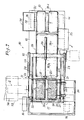
- the machine 10 represented in FIGS. 6 and 7 comprises, in known manner, a device 11 for making loads, also called “palletizer”, a strapping device 12, an evacuation station 13 and a provision conveyor strif 14 suitable for conveying a packaged bundle from the packaging device 11, through the strapping device 12 to the evacuation station 13. All these elements can be placed on a chassis 15 which is preferably provided with four wheels 16, including two directors, to be able to be brought close to the place of unloading of the bags 2, for example by means of a forklift serving as a tractor.
- Mechanical jacks can be provided to secure the chassis 15 in the workplace.
- the machine 10 At its left end (seen in FIGS. 6 and 7), that is to say near the device 11 for making the loads, the machine 10 comprises a working platform 17 to which a handler can access by a staircase 18.
- the manufacturing device 11 comprises a lifting table 19 movable between a high position shown in solid lines in Figure 6 and a low position shown in phantom in this same figure.
- the upper and lower positions of the lifting table 19 are spaced from each other by a distance slightly greater than the height of the burden to be made, for example a little more than seven times the height of a bag 2 in the case 1 should have seven layers of bags.
- the lifting table 19 supports a first conveyor 14a which can for example consist of two endless conveyor belts spaced transversely as shown in FIG. 7 so as to support the two bags 2 respectively of the base layer of the burden 1 being made .
- a rectangular and substantially horizontal plate 20 provided with rollers 21 can roll on two rails 22 and 23 which extend substantially horizontally and which are supported at a level situated above the high position of the conveyor 14a by an appropriate support structure which has not been shown so as not to overload Figures 6 and 7.
- the plate 20 can be moved substantially horizontally by two hydraulic or pneumatic cylinders 24 with double effect between a first position located above the conveyor 14a and a second position located away from said conveyor.
- the tray 20 has two large sides which extend transversely to the longitudinal direction of the conveyor 14a and which have a length substantially equal to the sum of the length and the width of a bag 2, and two short sides which extend in the longitudinal direction of the conveyor 14a and which have a length substantially equal to the length of a bag 2.
- a fixed vertical positioning plate 25 is disposed above and along one of the two long sides of the plate 20 when the latter is in its first position.
- the positioning plate 25 can be fixed to the rails 22 and 23 or to their support structure.
- the making-up device 11 further comprises retractable means for positioning the bags 2 making up the base layer of the burden 1 during making, these retractable means of positioning allowing, when they are in an active position, to provide at least one free space in the base layer of the burden being prepared.
- the retractable positioning means may comprise two vertical plates 26 and 27 arranged perpendicular to the fixed vertical plate 25 and just above the tray 20 when the latter is in its first position.
- the vertical plate 26 can be moved horizontally by two hydraulic or pneumatic cylinders 28 with double effect between a first position located along one of the two short sides of the plate 20 and a second position (shown in solid line in FIG. 7) located at a predetermined distance from said small side of the plate 20 towards the middle of the latter.
- the vertical plate 27 can be moved horizontally by another pneumatic or hydraulic jack 29 with double effect between a first position (shown in phantom in Figure 6) spaced from the plate 20 and a second position (shown in solid line in Figure 7 ) located at a distance from the other short side of the plate 20, which is equal to the sum of said predetermined distance and the width of a bag 2.
- the fixed vertical plate 25 has a vertical slot or is divided into two parts to allow the vertical plate 27 to pass from its first position to 14a, three other conveyors 14b, 14c and 14d arranged one after the other and at the same level as the conveyor 14a when the latter occupies its low position.
- the conveyor 14d located in the evacuation station 13 is constituted by two endless conveyor belts spaced transversely from one another in the same way as the two conveyor belts of the conveyor 4a,
- a tube distributor 30 suitable for bringing tubes 7 one by one into the space between the two conveyor belts of the conveyor 14d.
- the distributor 30 may for example comprise a tank or tube store 31, the bottom of which communicates with a curved chute 32 which passes under one of the two conveyor belts of the conveyor 14d to bring the tubes 7 one by one by gravity into said space.
- the two conveyor belts of the conveyor 14d can play the role of the two supports 6 shown in FIG. 1.
- the bags 2 unloaded from a truck or wagon are shaped in a known manner, for example by means of a vibration flattener device 33, and they are then conveyed in the longitudinal direction to the making device 11 using one or more conveyors 34 as shown in phantom in Figure 7.
- the lifting table 19 and its conveyor 14a are placed in the high position shown in Figure 6
- the plate 20 is placed by means of the two jacks 24 above the conveyor 14a
- the vertical plate 27 is retracted into the position shown in phantom in FIG. 6 by means of the jack 29, and the vertical plate 26 is placed in the position shown in solid lines in FIG. 7 by means of the two jacks 28.
- the first bag 2 brought by the conveyor 34 on the plate 20 is oriented in the longitudinal direction of the conveyor 14a and placed in the angle formed by the plates 25 and 26 by handling on the work platform 17.
- the handler then operates, for example by means of a control pedal not shown, the jack 29 in order to bring the vertical plate 27 into the active position shown in FIG. 7.
- the second bag brought by the conveyor 34 on the plate 20 is oriented longitudinally and placed by the handler in the angle formed by the plates 25 and 27 vertical.
- the upper surface of the plate 20 can be furnished in known manner with a multitude of balls on which the 2 bags can be easily moved and rotated.
- the plate 20 can be a fluidized type plate, that is to say provided with a multitude of nozzles delivering jets of compressed air making it possible to create an air cushion under the bags 2 brought to the tray 20.
- the rail 23 may be located at a level slightly lower than the rail 22, and the rails 22 and 23 may be slightly inclined downward relative to the horizontal towards the right end of the machine 10 seen in Figures 6 and 7, so that the bags 2 are automatically placed by gravity against the vertical plates 25 and 26 or 25 and 27.
- the vertical plate 26 makes it possible to form the free space 4 which is located on one of the two sides of the base layer of the burden 1 shown in FIG. 1, while the vertical plate 27 makes it possible to form the two other free spaces 4 which are respectively in the middle of said base layer and on the side thereof opposite the free space defined by the vertical plate 26.
- the plate 20 is moved substantially horizontally away from the lifting table 19 by the two jacks 24. During this movement of the plate 20, the two bags 2 of the layer of base are retained by the vertical plate 25 and fall respectively on the conveyor belts of the conveyor 14a.
- the lifting table 19 is then lowered by the height of a bag 2 and the plate 20 is returned to its first position above the bags 2 of the base layer by the two jacks 24.
- the plate 26 is then brought into its retracted position along the short side of the plate 20 by the two jacks 28, while the tray 20 by means of the jacks 24.
- shims may be optionally provided on the lifting table between the two conveyor belts of the conveyor 14a and on each side of the latter to support the parts of the bags the second layer which does not are not supported by the base layer bags.
- the third layer of the load 1 can be formed.
- the sixth bag brought. rar the conveyor 34 is placed by the handler with the same orientation as the two bags of the base layer against the vertical plates 25 and 26, the seventh bag is placed with an orientation perpendicular to that of the bags of the base layer against the plate 25 and the sixth bag, and the eighth bag is placed with the same orientation as the seventh bag against the sixth and seventh bags.
- the third layer thus formed is then deposited on the second layer.
- the following layers are formed similarly, the bags 2 of the fourth and sixth layers being arranged in the same way as those of the second layer, and the bags 2 of the fifth and seventh layers being arranged in the same way as those of the third layer, so as to form successive crossed layers.
- the strapping device 12 which may be of a known type, two links 3 are successively placed around the load 1.
- the strapping device 12 is adjusted in such a way that the links surrounding the burden 1 have a very low or moderate tension.
- the axis of the loops formed by the two links 3 is parallel to the longitudinal direction of the free spaces provided between the bags of the base layer.
- the strapping material intended to form the links 3 can be constituted by a plastic tape about 16 mm in width.
- the ribbon can be delivered to the strapping device 12 from a reel mounted in a support 35 itself pivotally mounted on one side of the chassis between a working position shown in solid lines on the. FIG. 6 and in phantom in FIG. 7, and a transport position shown in solid line in FIG. 7.
- the burden 1 is transferred by the conveyors 14c and 14d to the evacuation station 13 where it can be taken in charge at the same time as a tube 7 by a forklift in the manner which has already been described above with reference to Figures 1 and 2.
- the advance of the burden 1 through the strapping device 12, the successive stops of this burden in the two strapping positions and in the standby position at the evacuation station 13, and the strapping operations can be controlled automatically by example by means of the signals emitted by photoelectric cells placed in appropriate bins along the path followed by the burden 1. It therefore suffices for a single person to operate the machine 10, namely the handler who is on the platform 17. The latter can control the operation of the jacks 24, 28 and 29 and of the lifting table 19 from a control panel not shown.
- each burden consists of 20 bags of 50 kg each, or a total of one tonne
- the machine 10 can have a throughput of 30 tonnes per hour.
Landscapes
- Engineering & Computer Science (AREA)
- Mechanical Engineering (AREA)
- Pallets (AREA)
- Forklifts And Lifting Vehicles (AREA)
- Packaging Of Machine Parts And Wound Products (AREA)
- Basic Packing Technique (AREA)
Applications Claiming Priority (2)
| Application Number | Priority Date | Filing Date | Title |
|---|---|---|---|
| FR7732684 | 1977-10-28 | ||
| FR7732684A FR2407145A1 (fr) | 1977-10-28 | 1977-10-28 | Fardeau du type comprenant plusieurs couches superposees de charges unitaires, procede et machine pour sa realisation |
Publications (2)
| Publication Number | Publication Date |
|---|---|
| EP0001941A1 true EP0001941A1 (de) | 1979-05-16 |
| EP0001941B1 EP0001941B1 (de) | 1981-11-04 |
Family
ID=9197091
Family Applications (1)
| Application Number | Title | Priority Date | Filing Date |
|---|---|---|---|
| EP78400138A Expired EP0001941B1 (de) | 1977-10-28 | 1978-10-19 | Aus mehreren Schichten übereinander gestapelter Ladeeinheiten bestehende Ladung, sowie Verfahren und Maschine zu deren Ausführung |
Country Status (6)
| Country | Link |
|---|---|
| US (1) | US4240340A (de) |
| EP (1) | EP0001941B1 (de) |
| DE (1) | DE2861290D1 (de) |
| ES (1) | ES474866A1 (de) |
| FR (1) | FR2407145A1 (de) |
| IT (1) | IT1106597B (de) |
Cited By (2)
| Publication number | Priority date | Publication date | Assignee | Title |
|---|---|---|---|---|
| EP1852362A1 (de) * | 2006-04-28 | 2007-11-07 | 3 S's Limited | Verfahren zum Zusammenstellen einer Ladung für den Transport |
| CN113291520A (zh) * | 2021-05-18 | 2021-08-24 | 浙江百事特包装科技股份有限公司 | 一种防撞式穿剑打包机 |
Families Citing this family (2)
| Publication number | Priority date | Publication date | Assignee | Title |
|---|---|---|---|---|
| IT1135263B (it) * | 1981-02-02 | 1986-08-20 | Meschi Ind Grafica | Apparecchio di ricezione e trasferimento di materiale in foglio |
| GB2589923B (en) * | 2019-12-13 | 2021-12-08 | Three Smith Group Ltd | Strapping apparatus |
Citations (5)
| Publication number | Priority date | Publication date | Assignee | Title |
|---|---|---|---|---|
| DE1586549A1 (de) * | 1967-06-24 | 1970-08-13 | Hoffmann Cyklop | Verfahren und Vorrichtung zum Paketieren und Umreifen von Steinen oder anderen Formkoerpern |
| DE1756480A1 (de) * | 1968-05-28 | 1970-08-20 | Atlas Mak Maschb Gmbh | Vorrichtung zum Transportieren von Steinpaketen |
| FR2171328A1 (de) * | 1972-02-11 | 1973-09-21 | Magnusson Gustav | |
| US3788462A (en) * | 1971-02-25 | 1974-01-29 | Owens Illinois Inc | Unitized palletless load |
| DE2303128A1 (de) * | 1973-01-23 | 1974-08-01 | Platmanufaktur Ab | Aus mehreren schichten aufeinander gestapelter verpackungsgegenstaende bestehendes kolli, sowie verfahren und maschine zur herstellung desselben |
Family Cites Families (5)
| Publication number | Priority date | Publication date | Assignee | Title |
|---|---|---|---|---|
| US2609923A (en) * | 1949-10-27 | 1952-09-09 | St Regis Paper Co | Bag package with fork-lift handling means |
| US3057289A (en) * | 1955-02-21 | 1962-10-09 | Erapa Ets | Strapping apparatus |
| NL6401838A (de) * | 1964-02-26 | 1965-08-27 | ||
| US3642151A (en) * | 1970-01-26 | 1972-02-15 | Potlatch Forests Inc | Sheet-handling apparatus |
| US3688920A (en) * | 1971-06-01 | 1972-09-05 | William G Frish | Palletizing apparatus |
-
1977
- 1977-10-28 FR FR7732684A patent/FR2407145A1/fr active Granted
-
1978
- 1978-10-10 IT IT51440/78A patent/IT1106597B/it active
- 1978-10-19 DE DE7878400138T patent/DE2861290D1/de not_active Expired
- 1978-10-19 EP EP78400138A patent/EP0001941B1/de not_active Expired
- 1978-10-27 ES ES474866A patent/ES474866A1/es not_active Expired
-
1979
- 1979-07-11 US US06/056,618 patent/US4240340A/en not_active Expired - Lifetime
Patent Citations (5)
| Publication number | Priority date | Publication date | Assignee | Title |
|---|---|---|---|---|
| DE1586549A1 (de) * | 1967-06-24 | 1970-08-13 | Hoffmann Cyklop | Verfahren und Vorrichtung zum Paketieren und Umreifen von Steinen oder anderen Formkoerpern |
| DE1756480A1 (de) * | 1968-05-28 | 1970-08-20 | Atlas Mak Maschb Gmbh | Vorrichtung zum Transportieren von Steinpaketen |
| US3788462A (en) * | 1971-02-25 | 1974-01-29 | Owens Illinois Inc | Unitized palletless load |
| FR2171328A1 (de) * | 1972-02-11 | 1973-09-21 | Magnusson Gustav | |
| DE2303128A1 (de) * | 1973-01-23 | 1974-08-01 | Platmanufaktur Ab | Aus mehreren schichten aufeinander gestapelter verpackungsgegenstaende bestehendes kolli, sowie verfahren und maschine zur herstellung desselben |
Cited By (3)
| Publication number | Priority date | Publication date | Assignee | Title |
|---|---|---|---|---|
| EP1852362A1 (de) * | 2006-04-28 | 2007-11-07 | 3 S's Limited | Verfahren zum Zusammenstellen einer Ladung für den Transport |
| CN113291520A (zh) * | 2021-05-18 | 2021-08-24 | 浙江百事特包装科技股份有限公司 | 一种防撞式穿剑打包机 |
| CN113291520B (zh) * | 2021-05-18 | 2022-07-19 | 浙江百事特包装科技股份有限公司 | 一种防撞式穿剑打包机 |
Also Published As
| Publication number | Publication date |
|---|---|
| IT1106597B (it) | 1985-11-11 |
| FR2407145B1 (de) | 1982-02-19 |
| FR2407145A1 (fr) | 1979-05-25 |
| US4240340A (en) | 1980-12-23 |
| ES474866A1 (es) | 1979-03-16 |
| EP0001941B1 (de) | 1981-11-04 |
| IT7851440A0 (it) | 1978-10-10 |
| DE2861290D1 (en) | 1982-01-14 |
Similar Documents
| Publication | Publication Date | Title |
|---|---|---|
| EP2411308B1 (de) | Palettierer mit schachtelschichtbereitung | |
| US6775956B1 (en) | Wrapping method and apparatus | |
| CN1050334C (zh) | 物品打包的方法和设备 | |
| FR2879565A1 (fr) | Dispositif et procede d'emballage de pneumatiques | |
| FR2814161A1 (fr) | Dispositif de palettisation a tetes de depose multiples | |
| FR2971237A1 (fr) | Installation pour la manutention et le stockage d'au moins un contenant sur une palette | |
| EP0592314B1 (de) | Verfahren und Vorrichtung zum Verpacken von zusammendrückbaren Isolationsprodukten | |
| FR2710580A1 (fr) | Maintien d'une charge dans un emballage et dispositif de coupe d'emballage. | |
| EP0001941B1 (de) | Aus mehreren Schichten übereinander gestapelter Ladeeinheiten bestehende Ladung, sowie Verfahren und Maschine zu deren Ausführung | |
| EP0080063B1 (de) | Verfahren und Vorrichtung zum Stapeln von ineinandergreifenden Gussrohren | |
| FR2781471A1 (fr) | Dispositif de palettisation comprenant une alimentation de palettes vides par le haut | |
| FR2530228A1 (fr) | Dispositif de palettisation pour le chargement de palettes, par couches, avec des plateaux | |
| FR2560173A1 (fr) | Appareil pour decharger des palettes portant des couches d'articles | |
| FR2575134A1 (fr) | Installation de palettisation notamment de paquets de sacs | |
| FR2630718A1 (fr) | Procede et installation pour le compactage et le transport de produits en vrac de faible densite | |
| FR2587311A1 (fr) | Procede et installation de manutention automatique et stockage temporaire de paquets empiles de produits semi-finis en feuilles. | |
| BE1003735A7 (fr) | Methode et appareil de palettisation. | |
| EP0384869B1 (de) | Verfahren und Vorrichtung zum Stapeln zylindrischer Gegenstände in Schichten auf einem Träger, insbesondere auf einer Palette | |
| FR2976273A1 (fr) | Machine et procede pour la fusion ou la division automatique de charges palettisees | |
| FR2491444A1 (fr) | Chariot porteur, notamment pour postes de transfert de charges telles que des piles ou palettes d'objets | |
| FR2473021A1 (fr) | Chargeur de palettes concu pour des marchandises en colis, et tout specialement des paquets, sacs ou equivalent, groupees en differentes couches correspondant aux dimensions des palettes | |
| EP1775242A1 (de) | Palettierverfahren und Vorrichtung zur Durchführung dieses Verfahrens | |
| EP1529732B1 (de) | Lagerungsrahmen sowie Verfahren zum Handhaben eines Sackes in diesem Rahmen | |
| EP0671327B1 (de) | Verfahren und Anlage um pyramidenstumpfförmige Schalen handzuhaben und um diese in eine Verpackung einzusetzen | |
| FR3070680A1 (fr) | Transfert de couches de produits depuis ou jusque sur le dessus d'une palette |
Legal Events
| Date | Code | Title | Description |
|---|---|---|---|
| PUAI | Public reference made under article 153(3) epc to a published international application that has entered the european phase |
Free format text: ORIGINAL CODE: 0009012 |
|
| AK | Designated contracting states |
Designated state(s): BE CH DE GB LU NL SE |
|
| 17P | Request for examination filed | ||
| R17P | Request for examination filed (corrected) | ||
| GRAA | (expected) grant |
Free format text: ORIGINAL CODE: 0009210 |
|
| AK | Designated contracting states |
Designated state(s): BE CH DE GB LU NL SE |
|
| REF | Corresponds to: |
Ref document number: 2861290 Country of ref document: DE Date of ref document: 19820114 |
|
| PG25 | Lapsed in a contracting state [announced via postgrant information from national office to epo] |
Ref country code: LU Free format text: LAPSE BECAUSE OF NON-PAYMENT OF DUE FEES Effective date: 19821031 |
|
| PGFP | Annual fee paid to national office [announced via postgrant information from national office to epo] |
Ref country code: LU Payment date: 19830929 Year of fee payment: 6 |
|
| PGFP | Annual fee paid to national office [announced via postgrant information from national office to epo] |
Ref country code: CH Payment date: 19840924 Year of fee payment: 7 |
|
| PGFP | Annual fee paid to national office [announced via postgrant information from national office to epo] |
Ref country code: SE Payment date: 19840930 Year of fee payment: 7 Ref country code: BE Payment date: 19840930 Year of fee payment: 7 |
|
| PGFP | Annual fee paid to national office [announced via postgrant information from national office to epo] |
Ref country code: DE Payment date: 19841220 Year of fee payment: 7 |
|
| PGFP | Annual fee paid to national office [announced via postgrant information from national office to epo] |
Ref country code: NL Payment date: 19851031 Year of fee payment: 8 |
|
| PG25 | Lapsed in a contracting state [announced via postgrant information from national office to epo] |
Ref country code: SE Effective date: 19861020 |
|
| PG25 | Lapsed in a contracting state [announced via postgrant information from national office to epo] |
Ref country code: CH Effective date: 19861031 Ref country code: BE Effective date: 19861031 |
|
| BERE | Be: lapsed |
Owner name: LOGISAC GROUPEMENT D'INTERET ECONOMIQUE REGI PAR Effective date: 19861031 |
|
| PG25 | Lapsed in a contracting state [announced via postgrant information from national office to epo] |
Ref country code: NL Effective date: 19870501 |
|
| NLV4 | Nl: lapsed or anulled due to non-payment of the annual fee | ||
| REG | Reference to a national code |
Ref country code: CH Ref legal event code: PL |
|
| GBPC | Gb: european patent ceased through non-payment of renewal fee | ||
| PG25 | Lapsed in a contracting state [announced via postgrant information from national office to epo] |
Ref country code: DE Effective date: 19870901 |
|
| PG25 | Lapsed in a contracting state [announced via postgrant information from national office to epo] |
Ref country code: GB Effective date: 19881117 |
|
| EUG | Se: european patent has lapsed |
Ref document number: 78400138.0 Effective date: 19870811 |
|
| PLBE | No opposition filed within time limit |
Free format text: ORIGINAL CODE: 0009261 |
|
| STAA | Information on the status of an ep patent application or granted ep patent |
Free format text: STATUS: NO OPPOSITION FILED WITHIN TIME LIMIT |