EP0001961A2 - Procédé d'usinage sur tour automatique - Google Patents
Procédé d'usinage sur tour automatique Download PDFInfo
- Publication number
- EP0001961A2 EP0001961A2 EP78810019A EP78810019A EP0001961A2 EP 0001961 A2 EP0001961 A2 EP 0001961A2 EP 78810019 A EP78810019 A EP 78810019A EP 78810019 A EP78810019 A EP 78810019A EP 0001961 A2 EP0001961 A2 EP 0001961A2
- Authority
- EP
- European Patent Office
- Prior art keywords
- machining
- station
- main
- lathe
- automatic lathes
- Prior art date
- Legal status (The legal status is an assumption and is not a legal conclusion. Google has not performed a legal analysis and makes no representation as to the accuracy of the status listed.)
- Ceased
Links
Images
Classifications
-
- B—PERFORMING OPERATIONS; TRANSPORTING
- B23—MACHINE TOOLS; METAL-WORKING NOT OTHERWISE PROVIDED FOR
- B23B—TURNING; BORING
- B23B11/00—Automatic or semi-automatic turning-machines incorporating equipment for performing other working procedures, e.g. slotting, milling, rolling
-
- B—PERFORMING OPERATIONS; TRANSPORTING
- B23—MACHINE TOOLS; METAL-WORKING NOT OTHERWISE PROVIDED FOR
- B23Q—DETAILS, COMPONENTS, OR ACCESSORIES FOR MACHINE TOOLS, e.g. ARRANGEMENTS FOR COPYING OR CONTROLLING; MACHINE TOOLS IN GENERAL CHARACTERISED BY THE CONSTRUCTION OF PARTICULAR DETAILS OR COMPONENTS; COMBINATIONS OR ASSOCIATIONS OF METAL-WORKING MACHINES, NOT DIRECTED TO A PARTICULAR RESULT
- B23Q39/00—Metal-working machines incorporating a plurality of sub-assemblies, each capable of performing a metal-working operation
- B23Q39/04—Metal-working machines incorporating a plurality of sub-assemblies, each capable of performing a metal-working operation the sub-assemblies being arranged to operate simultaneously at different stations, e.g. with an annular work-table moved in steps
- B23Q39/042—Metal-working machines incorporating a plurality of sub-assemblies, each capable of performing a metal-working operation the sub-assemblies being arranged to operate simultaneously at different stations, e.g. with an annular work-table moved in steps with circular arrangement of the sub-assemblies
- B23Q39/046—Metal-working machines incorporating a plurality of sub-assemblies, each capable of performing a metal-working operation the sub-assemblies being arranged to operate simultaneously at different stations, e.g. with an annular work-table moved in steps with circular arrangement of the sub-assemblies including a loading and/or unloading station
Definitions
- the present invention consists of a machining process, on an automatic lathe comprising a main machining station and a secondary machining station, of parts which have been roughly pre-shaped.
- automatic lathes are used for machining from rough parts.
- the part is, in general, loaded on the machine by a suitable device and clamped in a mandrel. This is particularly the case for automatic lathes working only in chucks, multi-spindle lathes with fixed headstock especially.
- most automatic lathes working on the bar can also be used, with simple modifications, for work on rough parts, loaded by a suitable device (Jager H., Drehautomaten, Hanser Ober, 1967, p. 21, 72, 296 et seq.).
- secondary station means a device fitted with one or more tools and a means of holding the part during machining, device being mounted on the lathe and receiving the part by automatic transport after machining in the main station.
- a simple case is that of the screw made on a single spindle lathe.
- the method according to the invention is characterized in that the blanks are brought into the automatic lathe in the secondary machining station for a first operation, the lathe then transporting the partially machined blank in the main machining station.
- the advantage obtained consists in being able to machine a reference surface on the part in a secondary station having few tools, and in being able to complete the machining in the main machining station with, on the one hand, normal precision obtainable by the machine in question, and on the other hand the more numerous tools available to the main machining station.
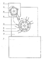
- Fig. I shows a front view of the spindle frame of a multi-spindle lathe with a main station and a secondary station for normal use.
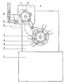
- Fig. It shows an identical view with the modifications for the use according to the invention.
- the base of the multi-spindle automatic lathe is designated by 1, 2 designates the frame of the pins in which is housed the barrel 3 comprising the pins 4.
- This barrel with the tool holders 5 forms the main machining station for the lathe .
- the transport lever is designated by 6.
- the secondary machining station consists of the addition 7 to the frame 2 and the indexable disc 8, which, with the jaws 9 serves as a workpiece carrier.
- Figures I and II differ in that fig. It further comprises a coin loader consisting of the magazine 10 and the loading lever 11.
- a coin loader consisting of the magazine 10 and the loading lever 11.
- the method according to the invention can be better carried out, in the case of a secondary station with indexable element , by intervening in the kinematics so as to index this element in the opposite direction, the arrow of FIG. It indicates a direction of rotation contrary to FIG. I.
Landscapes
- Engineering & Computer Science (AREA)
- Mechanical Engineering (AREA)
- Turning (AREA)
Abstract
Lors de l'utilisation de tours automatiques ceux-ci sont souvent pourvus d'un poste d'usinage secondaire, où la pièce est encore usinée après la coupe. Le procédé selon l'invention prévoit l'utilisation de tels tours automatiques, équipés de postes d'usinage secondaires pour l'usinage de pièces préalablement ébauchées. Selon le procédé, l'ébauche est chargée en premier lieu dans le poste d'usinage secondaire et ensuite dans le poste d'usinage principal. L'avantage obtenu consiste à pouvoir usiner dans un premier serrage une surface de référence servant au serrage dans la position d'usinage principale.
Description
- La présente invention consiste en un procédé d'usinage, sur tour automatique comportant un poste d'usinage principal et un poste d'usinage secondaire, de pièces préalablement ébauchées.
- Parfois on utilise des tours automatiques pour l'usinage à partir de pièces ébauchées. Dans ce cas la pièce est, en général, chargée sur la machine par un dispositif adéquat et serrée dans un mandrin. Ceci est le cas particulièrement pour les tours automatiques travaillant uniquement en mandrin, les tours multibroches à poupée fixe spécialement. Toutefois, la plupart des tours automatiques travaillant à la barre peuvent également être utilisés, en procédant à des modifica- .tions simples, pour des travaux de pièces ébauchées, chargées par un dispositif adéquat (Jager H., Drehautomaten, Hanser München, 1967, p. 21, 72, 296 et suivantes).
- Des tours automatiques avec un poste d'usinage principal et un ou plusieurs postes d'usinage secondaire existent depuis longtemps. Qu'il s'agisse de tours automatiques monobroches ou multibroches, l'on entend par poste secondaire un dispositif muni d'un ou de plusieurs outils et d'un moyen de tenir la pièce pendant l'usinage, dispositif étant monté sur le tour et recevant la pièce par transport automatique après l'usinage dans le poste principal. Un cas simple est celui de la vis faite sur un tour monobroche. Dans la position principale on tourne la jambe de la vis et effectue le filetage; la pièce étant serrée du côté de la tête de la vis, il n'est pas possible de fraiser la fente: lors de la coupe, si l'on travaille à la barre, au desserrage si l'on travaille en mandrin, le transporteur vient prendre la pièce pour l'amener dans le poste d'usinage secondaire où la tête est fendue par un appareil à fraiser (brevet suisse 124 275).
- Dans les tours automatiques multibroches on procède de la même façon. Il existe toutefois des tours multibroches avec un poste d'usinage secondaire plus sophistiqué comportant un moyen porte-pièce indexable et plusieurs positions d'usinage (brevet allemand DPS 12 03 572).
- Il est évident qu'un tour automatique avec poste principal et poste secondaire peut également être utilisé pour usiner des pièces ébauchées.
- Il existe toutefois un inconvénient très important en chargeant dans la broche ou le mandrin d'un tour des pièces ébauchées par matriçage, par forgeage, qui ont été coulées ou roulées. Etant donné que ces pièces ont une finition grossière et sont irrégulières, il est très difficile, par leur serrage dans la pince de la broche ou dans le mandrin du tour, d'obtenir des tolérances serrées et une concentri- cité suffisante sur les pièces terminées.
- Ces invonvénients ont pour conséquence que des pièces ébauchées doivent être usinées sur deux machines, sur la première on usine alors une surface de référence permettant un serrage concentrique et régulier, et sur la deuxième machine l'on peut dès lors usiner la pièce dans de bonnes conditions. Il va de soit qu'une telle méthode est onéreuse puisqu'elle demande la mise en service de deux machines et une manutention compliquée.
- Le procédé selon l'invention est caractérisé par le fait que les ébauches sont amenées dans le tour automatique dans le poste d'usinage secondaire pour une première opération, le tour transportant ensuite l'ébauche partiellement usinée dans le poste d'usinage principal.
- L'avantage obtenu consiste à pouvoir usiner une surface de référence sur la pièce dans un poste secondaire disposant de peu d'outils, et de pouvoir terminer l'usinage dans le poste d'usinage principal avec, d'une part, la précision normale pouvant être obtenue par la machine en question, et d'autre part les outils plus nombreux dont dispose le poste d'usinage principal.
- Les dessins annexés illustrent un exemple d'application de l'invention à l'aide d'un tour multibroche.
- La fig. I montre une vue de face du bâti des broches d'un tour multibroche avec un poste principal et un poste secondaire pour utilisation normale.
- La fig. II montre une vue identique avec les modifications pour l'utilisation selon l'invention.
- Dans les deux figures le socle du tour automatique multibroche est désigné par 1, 2 désigne le bâti des broches dans lequel est logé le barillet 3 comportant les broches 4. Ce barillet avec les porte-outils 5 forme le poste d'usinage principal du tour. Le levier transporteur est désigné par 6.Le poste d'usinage secondaire se compose de l'adjonction 7 au bâti 2 et du disque indexable 8, qui, avec les mors 9 sert de porte-pièce.
- Les figures I et II se différencient par le fait que la fig. II comporte en plus un chargeur de pièces se composant du magasin 10 et du levier de chargement 11. D'autre part, étant donné que le procédé selon l'invention peut être mieux réalisé, dans le cas d'un poste secondaire à élément indexable, en intervenant dans la cinématique de manière à indexer cet élément dans le sens contraire, la flèche de la fig. II indique un sens de rotation contraire à la fig. I.
- L'utilisation normale d'un tour automatique multibroche avec poste principal et poste secondaire, telle qu'elle ressort de la fig. I, est connue. La pièce est usinée dans le poste principal à partir d'une barre dan. les différentes stations que parcourt le barillet. Dans la dernière position la pièce est coupée de la barre et saisie par le levier transporteur 6 qui l'ammène dans les mors 9 du disque indexable 8. Par indexage de ce disque la pièce est amenée à nouveau dans différentes positions de travail. Lorsque la pièce a parcouru le cycle complet elle est terminée et les mors 9 s'ouvrent.
- L'utilisation d'un tel tour automatique multibroche selon l'invention et en se référant à l'exemple selon la fig. II, est par contre le suivant : les ébauches de pièces sont stockées dans le magasin 10. Le levier de chargement 11 les amène dans les wors de serrage 9 du disque indexable 8. Par indexation du disque 8, l'ébauche est alors amenée dans les positions de travail où elle est usinée par des dispositifs non- représentées. Lorsque, par indexages successives, l'ébauche arrive en position pour le levier transporteur 6, celui-ci la saisit et la transporte dans la broche correspondante. Dans cette broche elle est serrée par la surface de référence usinée précédement et peut maintenant subir tous les usinages nécessaires pour la terminer.
Claims (1)
- Procédé d'usinage, sur tour automatique comportant un poste d'usinage principal et un poste d'usinage secondaire, de pièces préalablement ébauchées, caractérisé par le fait que les ébauches sont amenées dans le tour automatique dans le poste d'usinage secondaire pour une première opération, le tour transportant ensuite l'ébauche partiellement usinée dans le poste d'usinage principal.
Applications Claiming Priority (2)
| Application Number | Priority Date | Filing Date | Title |
|---|---|---|---|
| CH1365477A CH618624A5 (fr) | 1977-11-09 | 1977-11-09 | |
| CH13654/77 | 1977-11-09 |
Publications (2)
| Publication Number | Publication Date |
|---|---|
| EP0001961A2 true EP0001961A2 (fr) | 1979-05-16 |
| EP0001961A3 EP0001961A3 (en) | 1979-05-30 |
Family
ID=4394210
Family Applications (1)
| Application Number | Title | Priority Date | Filing Date |
|---|---|---|---|
| EP78810019A Ceased EP0001961A3 (en) | 1977-11-09 | 1978-11-09 | Work processing on automatic lathes |
Country Status (2)
| Country | Link |
|---|---|
| EP (1) | EP0001961A3 (fr) |
| CH (1) | CH618624A5 (fr) |
Cited By (1)
| Publication number | Priority date | Publication date | Assignee | Title |
|---|---|---|---|---|
| CN105750983A (zh) * | 2016-05-06 | 2016-07-13 | 河海大学常州校区 | 一种自动钻床 |
Family Cites Families (6)
| Publication number | Priority date | Publication date | Assignee | Title |
|---|---|---|---|---|
| US2080157A (en) * | 1933-12-12 | 1937-05-11 | Bunting Brass & Bronze Co | Turning and facing machine |
| DE936176C (de) * | 1952-04-07 | 1955-12-07 | Hans Eberhard Dipl-Ing Tietz | Selbsttaetige Drehbank |
| CH412523A (de) * | 1964-03-12 | 1966-04-30 | Robert Et Schneider S A R L At | Spanabhebende Werkzeugmaschine |
| GB1190579A (en) * | 1966-08-12 | 1970-05-06 | Wickman Mach Tool Sales Ltd | Automatic Lathes. |
| FR2036204A5 (fr) * | 1969-03-06 | 1970-12-24 | Legris Fils | |
| DE2102150B2 (de) * | 1971-01-18 | 1975-11-06 | Index-Werke Kg Hahn & Tessky, 7300 Esslingen | Selbsttätige Drehmaschine |
-
1977
- 1977-11-09 CH CH1365477A patent/CH618624A5/fr not_active IP Right Cessation
-
1978
- 1978-11-09 EP EP78810019A patent/EP0001961A3/xx not_active Ceased
Cited By (1)
| Publication number | Priority date | Publication date | Assignee | Title |
|---|---|---|---|---|
| CN105750983A (zh) * | 2016-05-06 | 2016-07-13 | 河海大学常州校区 | 一种自动钻床 |
Also Published As
| Publication number | Publication date |
|---|---|
| CH618624A5 (fr) | 1980-08-15 |
| EP0001961A3 (en) | 1979-05-30 |
Similar Documents
| Publication | Publication Date | Title |
|---|---|---|
| EP2033725B1 (fr) | Dispositif d'alimentation et de déchargement automatique universel de pièces pour machine-outil | |
| FR2526343A1 (fr) | Tour automatique revolver multibroche | |
| AU2002220826A1 (en) | Actuator for workpiece holding device | |
| US20120161404A1 (en) | Workholding apparatus for machine tool | |
| CH647709A5 (en) | Machine tool with an automatic tool changer | |
| CH618624A5 (fr) | ||
| US5251510A (en) | Ring gear fixture and machining process therefor | |
| EP0936027B1 (fr) | Dispositif d'usinage en contre-opération pour une machine-outil | |
| US5207134A (en) | Automatic precision lathe | |
| US4754671A (en) | Combination cut-off tool/bar puller | |
| EP0027253A1 (fr) | Centre de tournage | |
| EP0032642A1 (fr) | Tour à broche horizontale | |
| SU1207633A1 (ru) | Токарный многошпиндельный прутковый автомат | |
| GB464733A (en) | Improvements in automatic lathes and like machines | |
| CH619166A5 (en) | Feed method for a multi-spindle automatic lathe and multi-spindle automatic lathe for implementing the method | |
| EP1632309B1 (fr) | Dispositif d'usinage en contre-opération dans un tour multibroches | |
| FR2546432A1 (fr) | Procede et appareil pour le chargement et le dechargement de pieces sur une machine-outil | |
| JPH0560705U (ja) | 旋 盤 | |
| JPS59161250A (ja) | 突切りバイトの折れ検出方法 | |
| JPS6464707A (en) | Automatic exchanger for collet unit | |
| FR2504037A1 (fr) | Centre de tournage a commande numerique permettant des operations de fraisage | |
| RU2138368C1 (ru) | Загрузочно-разгрузочное устройство | |
| FR2546434A1 (fr) | Pince pour pieces d'usinage montee sur tourelle pour machine de tournage | |
| SU593826A1 (ru) | Устройство дл съема обрабатываемых деталей | |
| JPS5856082Y2 (ja) | 工作物装入排出装置 |
Legal Events
| Date | Code | Title | Description |
|---|---|---|---|
| PUAI | Public reference made under article 153(3) epc to a published international application that has entered the european phase |
Free format text: ORIGINAL CODE: 0009012 |
|
| PUAL | Search report despatched |
Free format text: ORIGINAL CODE: 0009013 |
|
| AK | Designated contracting states |
Designated state(s): CH DE FR GB |
|
| AK | Designated contracting states |
Designated state(s): CH DE FR GB |
|
| 17P | Request for examination filed | ||
| STAA | Information on the status of an ep patent application or granted ep patent |
Free format text: STATUS: THE APPLICATION HAS BEEN REFUSED |
|
| 18R | Application refused |
Effective date: 19811031 |
|
| RIN1 | Information on inventor provided before grant (corrected) |
Inventor name: ROQUIER, FRANCIS |