EP0002111A1 - Appareil pour connecter des fils et la combinaison de l'appareil et d'un connecteur électrique - Google Patents
Appareil pour connecter des fils et la combinaison de l'appareil et d'un connecteur électrique Download PDFInfo
- Publication number
- EP0002111A1 EP0002111A1 EP78300553A EP78300553A EP0002111A1 EP 0002111 A1 EP0002111 A1 EP 0002111A1 EP 78300553 A EP78300553 A EP 78300553A EP 78300553 A EP78300553 A EP 78300553A EP 0002111 A1 EP0002111 A1 EP 0002111A1
- Authority
- EP
- European Patent Office
- Prior art keywords
- housing part
- connector
- operating station
- force applying
- applying member
- Prior art date
- Legal status (The legal status is an assumption and is not a legal conclusion. Google has not performed a legal analysis and makes no representation as to the accuracy of the status listed.)
- Withdrawn
Links
- 230000000694 effects Effects 0.000 claims abstract description 8
- 230000000295 complement effect Effects 0.000 claims abstract description 4
- 230000006835 compression Effects 0.000 description 1
- 238000007906 compression Methods 0.000 description 1
- 230000000717 retained effect Effects 0.000 description 1
Images
Classifications
-
- H—ELECTRICITY
- H01—ELECTRIC ELEMENTS
- H01R—ELECTRICALLY-CONDUCTIVE CONNECTIONS; STRUCTURAL ASSOCIATIONS OF A PLURALITY OF MUTUALLY-INSULATED ELECTRICAL CONNECTING ELEMENTS; COUPLING DEVICES; CURRENT COLLECTORS
- H01R4/00—Electrically-conductive connections between two or more conductive members in direct contact, i.e. touching one another; Means for effecting or maintaining such contact; Electrically-conductive connections having two or more spaced connecting locations for conductors and using contact members penetrating insulation
- H01R4/24—Connections using contact members penetrating or cutting insulation or cable strands
- H01R4/2416—Connections using contact members penetrating or cutting insulation or cable strands the contact members having insulation-cutting edges, e.g. of tuning fork type
- H01R4/242—Connections using contact members penetrating or cutting insulation or cable strands the contact members having insulation-cutting edges, e.g. of tuning fork type the contact members being plates having a single slot
- H01R4/2425—Flat plates, e.g. multi-layered flat plates
- H01R4/2429—Flat plates, e.g. multi-layered flat plates mounted in an insulating base
-
- H—ELECTRICITY
- H01—ELECTRIC ELEMENTS
- H01R—ELECTRICALLY-CONDUCTIVE CONNECTIONS; STRUCTURAL ASSOCIATIONS OF A PLURALITY OF MUTUALLY-INSULATED ELECTRICAL CONNECTING ELEMENTS; COUPLING DEVICES; CURRENT COLLECTORS
- H01R43/00—Apparatus or processes specially adapted for manufacturing, assembling, maintaining, or repairing of line connectors or current collectors or for joining electric conductors
- H01R43/01—Apparatus or processes specially adapted for manufacturing, assembling, maintaining, or repairing of line connectors or current collectors or for joining electric conductors for connecting unstripped conductors to contact members having insulation cutting edges
- H01R43/015—Handtools
Definitions
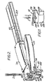
- the invention relates to apparatus for connecting wires in an electrical connector.
- the wire connecting apparatus is adapted to connect wires in the electrical connector shown in Figure 1 and described in more detail in our copending application (8994) of even date to which reference is hereby made.
- the connector 10 comprises upper and lower insulating housing parts 11 and 13 relatively rotatable by radially extending arms 26 and 49, respectively, to urge wires 2, when inserted in passageways 23, into a slotted contact member fixed in the lower housing part.
- the upper surface of the upper housing part 12 is formed with a pair of parallel grooves 29 on each side of the mouths of the passageways 23 and the lower surface of the lower housing part is formed with a single diametric groove 48.
- the wire connecting apparatus comprises a head 61 comprising a framework 62 defining a passageway providing a connector feed path 63 extending to an operating station 64.
- a plate member 66 defining an upper wall of the passageway is formed with two spaced parallel ribs 67 extending longitudinally and laterally offset from the centre line of the passageway for engagement in the complementary grooves 29 on the connectors to guide the connectors along the passageway in a constant rotational position.
- a spigot 68 upstands from a bottom wall 69 of the passageway at an exit end of the operating station to provide a connector stop.
- a trigger 71 is pivotally mounted at 72 in a clevis 73 provided in the head on one side of the connector feed path for movement relatively towards a handle 70 against the action of a compression spring 81.
- a bell crank lever 74 is pivotally mounted intermediate its ends on a frame extension 75.
- the short arm of the bell crank lever is formed with a slot 93 in which a pin 76 fixed to trigger 71 is freely located and the long arm of the bell crank lever arm extends under the connector feed path 62 into a cavity 77 provided in the head on the other side of the passageway.
- a pawl 78 is pivotally mounted on the free end of the long arm and biassed by spring 80 against a spigot 79 fixed in the arm defining with the bell crank lever an escapement mechanism.
- a flat coil spring 81 is mounted in a housing 82 mounted on the head and is adapted to provide a substantially constant biassing force irrespective of extended length.
- the handle 70 defines a through-passageway adapted releasably to receive a connector magazine 83.
- the magazine is of rectangular cross-section and defines a connector-receiving passageway 84 having a pair of connector guiding ribs 85 aligned with the ribs 67 in the operating head and laterally offset from the longitudinal centre line of the passageway to provide a clearance for connector arms 26,49.
- the magazine has a longitudinally extending slot 86 in a lower wall receiving a hooked end 87 of the spring 81.
- a loaded magazine is inserted into handle 70 and a hooked end 87 of the spring 81 engaged with the rearmost connector 10, urging the connectors in tandem relation along the feed path to the operating station retained in a constant rotational position by guiding ribs 67 and 85.
- the leading connector is restrained from movement beyond the exit end of the operating station by engagement with spigot 68.
- the wires are then inserted through slot 87 in plate member 66 into the connector. Operation of the trigger in the position shown in Figure 3 causes the pawl to engage arm 49 rotating the lower housing part relative to the upper housing part urging the slotted contact member against the wires to splice them electrically together.
Landscapes
- Engineering & Computer Science (AREA)
- Manufacturing & Machinery (AREA)
- Details Of Connecting Devices For Male And Female Coupling (AREA)
- Multi-Conductor Connections (AREA)
- Connector Housings Or Holding Contact Members (AREA)
- Manufacturing Of Electrical Connectors (AREA)
- Connections By Means Of Piercing Elements, Nuts, Or Screws (AREA)
Applications Claiming Priority (4)
| Application Number | Priority Date | Filing Date | Title |
|---|---|---|---|
| US05/850,171 US4173067A (en) | 1977-11-10 | 1977-11-10 | Applicator apparatus for use with rotary connector |
| US850584 | 1977-11-11 | ||
| US05/850,584 US4157208A (en) | 1977-11-11 | 1977-11-11 | Waterproof splice electrical connector |
| US850171 | 1997-05-02 |
Publications (1)
| Publication Number | Publication Date |
|---|---|
| EP0002111A1 true EP0002111A1 (fr) | 1979-05-30 |
Family
ID=27126907
Family Applications (2)
| Application Number | Title | Priority Date | Filing Date |
|---|---|---|---|
| EP78300556A Withdrawn EP0002113A1 (fr) | 1977-11-10 | 1978-10-27 | Connecteur électrique et la combinaison d'une série de ces connecteurs et d'un appareil de raccordement de fils électriques |
| EP78300553A Withdrawn EP0002111A1 (fr) | 1977-11-10 | 1978-10-27 | Appareil pour connecter des fils et la combinaison de l'appareil et d'un connecteur électrique |
Family Applications Before (1)
| Application Number | Title | Priority Date | Filing Date |
|---|---|---|---|
| EP78300556A Withdrawn EP0002113A1 (fr) | 1977-11-10 | 1978-10-27 | Connecteur électrique et la combinaison d'une série de ces connecteurs et d'un appareil de raccordement de fils électriques |
Country Status (6)
| Country | Link |
|---|---|
| EP (2) | EP0002113A1 (fr) |
| JP (2) | JPS5475586A (fr) |
| AU (1) | AU4109078A (fr) |
| BR (2) | BR7807357A (fr) |
| ES (2) | ES474876A1 (fr) |
| IT (2) | IT1100049B (fr) |
Families Citing this family (15)
| Publication number | Priority date | Publication date | Assignee | Title |
|---|---|---|---|---|
| US4318580A (en) * | 1980-06-09 | 1982-03-09 | Minnesota Mining And Manufacturing Company | Hand applied rotary connector |
| US4431247A (en) * | 1982-04-23 | 1984-02-14 | Minnesota Mining And Manufacturing Company | Insulated terminal and module |
| DE3233458C1 (de) * | 1982-09-09 | 1988-06-16 | C.A. Weidmüller GmbH & Co, 4930 Detmold | Schneidverbinder |
| FR2593969B1 (fr) * | 1986-01-24 | 1988-10-14 | Simon Guy | Dispositif de connexion auto-denudant |
| FR2618024B1 (fr) * | 1987-07-10 | 1992-11-13 | Arnould App Electr | Connecteur auto-denudant pour conducteur electrique |
| EP0312438B1 (fr) * | 1987-10-13 | 1994-01-19 | ARNOULD Fabrique d'Appareillage Electrique | Connecteur auto-dénudant pour conducteur électrique |
| FR2633456B1 (fr) * | 1988-06-24 | 1990-10-05 | Arnould App Electr | Connecteur autodenudant pour conducteur electrique |
| FR2626803B1 (fr) * | 1988-02-05 | 1991-12-06 | Legrand Sa | Distributeur a machoires de sertissage pour accessoire de cablage a sertir, en particulier embout |
| FR2637419B1 (fr) * | 1988-09-30 | 1990-12-21 | Saligny Yves | Connecteur auto-denudant, et appareillage electrique equipe d'au moins un tel connecteur |
| JP2514006Y2 (ja) * | 1990-04-16 | 1996-10-16 | 株式会社東電通 | Ccpコネクタプレス工具 |
| US5149278A (en) * | 1991-02-22 | 1992-09-22 | Psi Telecommunications, Inc. | Terminal block |
| GB2375237A (en) * | 2001-05-01 | 2002-11-06 | Yu-Ho Liang | Terminal connector |
| DE202009007530U1 (de) * | 2009-02-16 | 2010-07-15 | Weidmüller Interface GmbH & Co. KG | Steckbare Anschlussvorrichtung zum Anschluss eines Kabels an ein Anschlussgehäuse |
| DE102010041037A1 (de) * | 2010-09-20 | 2012-03-22 | Robert Bosch Gmbh | Schneidklemme zur Herstellung einer elektrischen Verbindung sowie Kontaktierungsanordnung mit einer derartigen Schneidklemme |
| CN114142319B (zh) * | 2021-12-16 | 2023-08-18 | 新昌浙江工业大学科学技术研究院 | 用于两段线束自动压接的设备 |
Citations (3)
| Publication number | Priority date | Publication date | Assignee | Title |
|---|---|---|---|---|
| US3707867A (en) * | 1970-03-12 | 1973-01-02 | Minnesota Mining & Mfg | Cartridge-type crimping tool |
| US3980380A (en) * | 1972-11-21 | 1976-09-14 | Bunker Ramo Corporation | Electrical connectors with plural simultaneously-actuated insulation-piercing contacts |
| FR2338592A1 (fr) * | 1976-01-13 | 1977-08-12 | Amp Inc | Appareil d'assemblage des deux parties d'un connecteur electrique |
-
1978
- 1978-10-26 AU AU41090/78A patent/AU4109078A/en active Pending
- 1978-10-27 EP EP78300556A patent/EP0002113A1/fr not_active Withdrawn
- 1978-10-27 EP EP78300553A patent/EP0002111A1/fr not_active Withdrawn
- 1978-10-31 IT IT29328/78A patent/IT1100049B/it active
- 1978-10-31 IT IT29329/78A patent/IT1100028B/it active
- 1978-11-07 ES ES474876A patent/ES474876A1/es not_active Expired
- 1978-11-07 ES ES474875A patent/ES474875A1/es not_active Expired
- 1978-11-08 BR BR7807357A patent/BR7807357A/pt unknown
- 1978-11-08 BR BR7807358A patent/BR7807358A/pt unknown
- 1978-11-09 JP JP13740678A patent/JPS5475586A/ja active Pending
- 1978-11-09 JP JP13740778A patent/JPS5475584A/ja active Pending
Patent Citations (3)
| Publication number | Priority date | Publication date | Assignee | Title |
|---|---|---|---|---|
| US3707867A (en) * | 1970-03-12 | 1973-01-02 | Minnesota Mining & Mfg | Cartridge-type crimping tool |
| US3980380A (en) * | 1972-11-21 | 1976-09-14 | Bunker Ramo Corporation | Electrical connectors with plural simultaneously-actuated insulation-piercing contacts |
| FR2338592A1 (fr) * | 1976-01-13 | 1977-08-12 | Amp Inc | Appareil d'assemblage des deux parties d'un connecteur electrique |
Also Published As
| Publication number | Publication date |
|---|---|
| IT1100028B (it) | 1985-09-28 |
| ES474876A1 (es) | 1979-11-01 |
| AU4109078A (en) | 1980-05-01 |
| IT7829329A0 (it) | 1978-10-31 |
| IT1100049B (it) | 1985-09-28 |
| BR7807357A (pt) | 1979-05-15 |
| EP0002113A1 (fr) | 1979-05-30 |
| ES474875A1 (es) | 1979-11-01 |
| BR7807358A (pt) | 1979-05-15 |
| JPS5475584A (en) | 1979-06-16 |
| IT7829328A0 (it) | 1978-10-31 |
| JPS5475586A (en) | 1979-06-16 |
Similar Documents
| Publication | Publication Date | Title |
|---|---|---|
| EP0002111A1 (fr) | Appareil pour connecter des fils et la combinaison de l'appareil et d'un connecteur électrique | |
| CA1043991A (fr) | Appareil pour poser une gaine isolante tubulaire a un connecteur electrique | |
| US4136440A (en) | Electrical harness fabrication method and apparatus | |
| US3997956A (en) | Wire insertion apparatus | |
| US4048710A (en) | Conductor terminating apparatus | |
| US4389769A (en) | Terminating tool which is adjustable to accommodate different centerline spacing | |
| GB2075903A (en) | Tool for forming a solderless screwless and stripless connection between an insulated wire and a longitudinally slotted terminal element | |
| JPH01253182A (ja) | 電気ハーネスの製造方法及び装置 | |
| EP0040491A1 (fr) | Appareil pour insérer des terminaux électriques dans un boîtier d'un connecteur électrique | |
| US4332083A (en) | Terminating apparatus for flat cable | |
| US4557048A (en) | Tool for assembling insulated connector | |
| US3995358A (en) | Applicator tool for multi-conductor connector | |
| US4019236A (en) | Crimping press clamp for electrical connectors | |
| US4754636A (en) | Connector locating device for crimping tools | |
| AU613146B2 (en) | Tool for connecting cable wires | |
| JP3032256B2 (ja) | シールドピン自動組立装置 | |
| JPH02278680A (ja) | 電気コネクタ製造装置 | |
| US3968555A (en) | Electrically operated programmable insertion tool with conductor guide and movable strain relief insertion mechanisms | |
| US4369819A (en) | Lead wire forming apparatus for electric parts | |
| US4175320A (en) | Conductor terminating apparatus | |
| US4345809A (en) | Circuit board ejector and guide | |
| US4451965A (en) | Method for installing a sleeve on a substrate | |
| US7281320B2 (en) | Waterproof-seal inserting apparatus | |
| US5903971A (en) | Wire termination apparatus for making wire harnesses | |
| US3152390A (en) | Electrical connector applying tool |
Legal Events
| Date | Code | Title | Description |
|---|---|---|---|
| PUAI | Public reference made under article 153(3) epc to a published international application that has entered the european phase |
Free format text: ORIGINAL CODE: 0009012 |
|
| AK | Designated contracting states |
Designated state(s): BE DE FR GB NL SE |
|
| 17P | Request for examination filed | ||
| STAA | Information on the status of an ep patent application or granted ep patent |
Free format text: STATUS: THE APPLICATION IS DEEMED TO BE WITHDRAWN |
|
| 18D | Application deemed to be withdrawn |
Effective date: 19810122 |
|
| RIN1 | Information on inventor provided before grant (corrected) |
Inventor name: SUCHESKI, MATTHEW MICHAEL Inventor name: ROBERTS, LINCOLN EDWIN Inventor name: YOUNG, WALTER MARTIN Inventor name: STEINER, CHARLES DALE |