EP0002132A2 - Procédé d'obtention de lignes de rupture dans une bande d'attaches - Google Patents
Procédé d'obtention de lignes de rupture dans une bande d'attaches Download PDFInfo
- Publication number
- EP0002132A2 EP0002132A2 EP78300638A EP78300638A EP0002132A2 EP 0002132 A2 EP0002132 A2 EP 0002132A2 EP 78300638 A EP78300638 A EP 78300638A EP 78300638 A EP78300638 A EP 78300638A EP 0002132 A2 EP0002132 A2 EP 0002132A2
- Authority
- EP
- European Patent Office
- Prior art keywords
- strip
- tools
- clips
- clip
- shear
- Prior art date
- Legal status (The legal status is an assumption and is not a legal conclusion. Google has not performed a legal analysis and makes no representation as to the accuracy of the status listed.)
- Granted
Links
Images



Classifications
-
- B—PERFORMING OPERATIONS; TRANSPORTING
- B26—HAND CUTTING TOOLS; CUTTING; SEVERING
- B26F—PERFORATING; PUNCHING; CUTTING-OUT; STAMPING-OUT; SEVERING BY MEANS OTHER THAN CUTTING
- B26F1/00—Perforating; Punching; Cutting-out; Stamping-out; Apparatus therefor
- B26F1/18—Perforating by slitting, i.e. forming cuts closed at their ends without removal of material
-
- B—PERFORMING OPERATIONS; TRANSPORTING
- B65—CONVEYING; PACKING; STORING; HANDLING THIN OR FILAMENTARY MATERIAL
- B65D—CONTAINERS FOR STORAGE OR TRANSPORT OF ARTICLES OR MATERIALS, e.g. BAGS, BARRELS, BOTTLES, BOXES, CANS, CARTONS, CRATES, DRUMS, JARS, TANKS, HOPPERS, FORWARDING CONTAINERS; ACCESSORIES, CLOSURES, OR FITTINGS THEREFOR; PACKAGING ELEMENTS; PACKAGES
- B65D33/00—Details of, or accessories for, sacks or bags
- B65D33/16—End- or aperture-closing arrangements or devices
- B65D33/1616—Elements constricting the neck of the bag
- B65D33/1625—Small plates or the like made of one piece and presenting slits or a central aperture to jam the neck of the bag
-
- Y—GENERAL TAGGING OF NEW TECHNOLOGICAL DEVELOPMENTS; GENERAL TAGGING OF CROSS-SECTIONAL TECHNOLOGIES SPANNING OVER SEVERAL SECTIONS OF THE IPC; TECHNICAL SUBJECTS COVERED BY FORMER USPC CROSS-REFERENCE ART COLLECTIONS [XRACs] AND DIGESTS
- Y10—TECHNICAL SUBJECTS COVERED BY FORMER USPC
- Y10S—TECHNICAL SUBJECTS COVERED BY FORMER USPC CROSS-REFERENCE ART COLLECTIONS [XRACs] AND DIGESTS
- Y10S206/00—Special receptacle or package
- Y10S206/82—Separable, striplike plural articles
-
- Y—GENERAL TAGGING OF NEW TECHNOLOGICAL DEVELOPMENTS; GENERAL TAGGING OF CROSS-SECTIONAL TECHNOLOGIES SPANNING OVER SEVERAL SECTIONS OF THE IPC; TECHNICAL SUBJECTS COVERED BY FORMER USPC CROSS-REFERENCE ART COLLECTIONS [XRACs] AND DIGESTS
- Y10—TECHNICAL SUBJECTS COVERED BY FORMER USPC
- Y10T—TECHNICAL SUBJECTS COVERED BY FORMER US CLASSIFICATION
- Y10T83/00—Cutting
- Y10T83/04—Processes
- Y10T83/0405—With preparatory or simultaneous ancillary treatment of work
- Y10T83/0419—By distorting within elastic limit
- Y10T83/0433—By flexing around or by tool
- Y10T83/0438—To conform to shape of tool
-
- Y—GENERAL TAGGING OF NEW TECHNOLOGICAL DEVELOPMENTS; GENERAL TAGGING OF CROSS-SECTIONAL TECHNOLOGIES SPANNING OVER SEVERAL SECTIONS OF THE IPC; TECHNICAL SUBJECTS COVERED BY FORMER USPC CROSS-REFERENCE ART COLLECTIONS [XRACs] AND DIGESTS
- Y10—TECHNICAL SUBJECTS COVERED BY FORMER USPC
- Y10T—TECHNICAL SUBJECTS COVERED BY FORMER US CLASSIFICATION
- Y10T83/00—Cutting
- Y10T83/04—Processes
- Y10T83/0448—With subsequent handling [i.e., of product]
-
- Y—GENERAL TAGGING OF NEW TECHNOLOGICAL DEVELOPMENTS; GENERAL TAGGING OF CROSS-SECTIONAL TECHNOLOGIES SPANNING OVER SEVERAL SECTIONS OF THE IPC; TECHNICAL SUBJECTS COVERED BY FORMER USPC CROSS-REFERENCE ART COLLECTIONS [XRACs] AND DIGESTS
- Y10—TECHNICAL SUBJECTS COVERED BY FORMER USPC
- Y10T—TECHNICAL SUBJECTS COVERED BY FORMER US CLASSIFICATION
- Y10T83/00—Cutting
- Y10T83/04—Processes
- Y10T83/0586—Effecting diverse or sequential cuts in same cutting step
-
- Y—GENERAL TAGGING OF NEW TECHNOLOGICAL DEVELOPMENTS; GENERAL TAGGING OF CROSS-SECTIONAL TECHNOLOGIES SPANNING OVER SEVERAL SECTIONS OF THE IPC; TECHNICAL SUBJECTS COVERED BY FORMER USPC CROSS-REFERENCE ART COLLECTIONS [XRACs] AND DIGESTS
- Y10—TECHNICAL SUBJECTS COVERED BY FORMER USPC
- Y10T—TECHNICAL SUBJECTS COVERED BY FORMER US CLASSIFICATION
- Y10T83/00—Cutting
- Y10T83/04—Processes
- Y10T83/0605—Cut advances across work surface
-
- Y—GENERAL TAGGING OF NEW TECHNOLOGICAL DEVELOPMENTS; GENERAL TAGGING OF CROSS-SECTIONAL TECHNOLOGIES SPANNING OVER SEVERAL SECTIONS OF THE IPC; TECHNICAL SUBJECTS COVERED BY FORMER USPC CROSS-REFERENCE ART COLLECTIONS [XRACs] AND DIGESTS
- Y10—TECHNICAL SUBJECTS COVERED BY FORMER USPC
- Y10T—TECHNICAL SUBJECTS COVERED BY FORMER US CLASSIFICATION
- Y10T83/00—Cutting
- Y10T83/869—Means to drive or to guide tool
- Y10T83/8821—With simple rectilinear reciprocating motion only
- Y10T83/8854—Progressively cutting
-
- Y—GENERAL TAGGING OF NEW TECHNOLOGICAL DEVELOPMENTS; GENERAL TAGGING OF CROSS-SECTIONAL TECHNOLOGIES SPANNING OVER SEVERAL SECTIONS OF THE IPC; TECHNICAL SUBJECTS COVERED BY FORMER USPC CROSS-REFERENCE ART COLLECTIONS [XRACs] AND DIGESTS
- Y10—TECHNICAL SUBJECTS COVERED BY FORMER USPC
- Y10T—TECHNICAL SUBJECTS COVERED BY FORMER US CLASSIFICATION
- Y10T83/00—Cutting
- Y10T83/929—Tool or tool with support
- Y10T83/9411—Cutting couple type
- Y10T83/9449—Spaced cut forming tool
Definitions
- the invention relates to clips for closing bags containing bread, food produce or other items as well as to methods for forming them.
- the clips are formed in strips, from laminar plastics material.
- Formation of the strips in this manner involves loss of material at the portions which are removed from between adjacent clips and the manner of separation of one clip from the next,which was a lateral displacement so as to break the webs at each of their ends, involves the production of stray chips of plastics (i.e. the severed webs) which can contaminate the food or other product within the bag if they should get within it, or can cause malfunction of the clip attaching mechanism. If the webs do not break in the intended fashion they can remain projecting from the edges of the clip to scratch or snag other products or hands of the users or purchasers of the bag.
- the clips produced still had the disadvantage the projections into the clips tended to separate from them when the clip was attached to a bag neck and removed from the strip and there was still therefore the difficulty of leaving these plastics material chips which could contaminate food or other products or of having projections projecting from the clips so as to scratch or snag the products or people. Also the flaps which form the projections, unless completely and accurately restored into the plane of the strip would tend to bias the strip into a curve and would prevent compactness in a roll of such strip.
- the problem therefore remains of providing a strip of clips of this general nature which is formed without substantial loss of material in the separation of one clip from the next without the need for a distinct planishing operation, and at the same time without leaving any possibility of protrusion out of the plane of the strip or of the presence of stray chips of material resulting from separation of joining webs or projections between clips. Furthermore, the problem is also faced of the finding of a method of forming such a clip without loss of material but at the same time without involving the material in the longitudinal apparent contraction which is essential in the process of U.K. Specification 1399906 clips and which necessarily also involves the separate planishing operation which must be completely successful unless the strips are to have ledges protruding which prevent compactness in a roll.
- the process of manufacture should also not be over-sensitive to variations in the quality of the material operated on and should avoid as far as possible the accumulation of debris in the tool, which latter can lead to inaccuracies (such as lack of planarity discussed above).
- the invention solves the problem of avoiding the production of chips of material or of snagging projections upon the separation of clips from the strip by forming breaking portions between individual clips of the strip which are of negligible longitudinal length. That is to say, they are coextensive longitudinally of the strip with a defining line, formed by shearing the material of the strip in a line which extends laterally of it, in a shearing operation which involves substantially no loss of material. There being no loss of material it follows that the line of definition is of negligible extension longitudinally of the strip.
- the separation line is formed by bowing the material of the strip about a longitudinal axis and shearing it while bowed by a shearing tool having an equal and opposite curvature.
- a plurality of these strips may be formed from an initial blank web of the material but the strips must be separated each from its lateral neighbour before the cutting operation is carried out which forms the line of separation of the individual clips in each strip. This is because the shearing operation as specified involves an apparent lateral contraction of each strip (as opposed to the apparent longitudinal contraction seen in the prior art process of U.K. Patent 1399906).
- the apertures formed in the lateral edges of these strips may have a particular form which assists in the smooth introduction of the bags into the clips and of their positive retention there.
- the aperture is essentially clover-leafed in shape and is linked to the lateral edge of the clip by a slot having a first portion of comparatively wide angle joined by a radiussed shoulder to a narrow slot, this latter debouching into the aperture adjacent recurved edge portions of the aperture which serve as barbs. Smooth and efficient introduction of the bag as well as prevention of its escape is aided by forming the narrower portion of the slot as a slot which tapers to narrow towards the aperture but at a very low angle of taper.
- clips 12 are joined adjacent opposite edges thereof to adjacent clips to form a strip 10, preferably rolled into a tight roll to facilitate handling and dispensing to a machine for attaching clips to necks of a bag.
- each clip 12a, 12b, and 12c is of identical construction.
- the longitudinal direction of the strip of clips is shown by arrow L.
- a web of a flexible plastics material such as polystyrene is moved through a five stage progressive die set for forming a plurality of strips 10 of clips 12.
- punches are employed for forming square diamond shaped holes 14 which will in the finished strips form notches having sides 15,16,17 and 18 at serrated edges of a strip 10 of clips 12 (Fig.2). Simultaneously with the forming of holes 14, other punches form apertures 20 in the web 13.
- bag receiving passage 22 is bounded by converging surfaces 24 and 26 to form a tapered slot portion for directing the neck of a bag through a narrow slot portion 25 bounded on opposite sides by surfaces 27 and 28 and a radiused shoulder 24a 26a is formed as a transition between the two.
- aperture 20 is important to the proper functioning of clip 12 for securely connecting the clip to the neck of a bag.
- the aperture 20 comprises a semi-circular portion 30 which has a surface which tangentially intersects with straight surfaces 32 and 34 .
- the opposite side of aperture 20 is formed by a pair of recurved surfaces 36 and 38 which intersect and 28 the side surfaces 27/of the slot 25 where the latter debauches into the aperture to form pointed barb-like projections 39 and 40.
- Curved surfaces 36 and 38 also tangentially intersect with straight surfaces 42 and 44 intersecting at approximately right angles with ledge surfaces 45 and 46. It should be appreciated that surfaces 32, 34, 42, and 44 are substantially parallel to each other and are perpendicular to surfaces 45 and 46.
- right angle projections 47 and 48 are formed which as will be explained later have a function in gripping a bag mouth when held in the aperture.
- the web 13 is cut along its longitudinal direction to define what will be a rear surface 50 and front surfaces 52 and 54 on each clip and to sever the web 13 so as to form a plurality of strips 10 of clips 12.
- the cutting operation is carried out by a longitudinally channeled punch working into a longitudinally extending channel die, with shear between the oncoming sharpened parallel edges of the punch and the walls of the die.
- no positive action is performed on the web 13.
- the fourth stage is provided to physically space the fifth stage E from the third stage C as diagrammatically illustrated in Figure 4.
- each of the transverse cuts 60 terminates inwardly of the apices 19 formed at the intersection of converging surfaces 15 and 16 and converging surfaces 17 and 18, respectively.
- portions 62 and 64 of strip 10 adjacent opposite ends of cut 60 are not severed and form breaking portions integral with each of the adjacent clips for breakably connecting adjacent clips.
- edges 65 and 66 of clip 12 adjacent opposite sides of cut 60 are moved in a shear plane 70 which corresponds to a plane of fracture 72 extending laterally of the strip between adjacent clips, the breaking portions 62 and 64 of strip 10 being in -the plane of fracture 72. That is, in forming individual clips 12 at stage E the material of web 13 is severed in the shear plane. When a clip 12b is removed from an adjacent clip 12a, the portions 62 and 64 are fractured in the plane of fracture 72 such that each clip has smooth edges which do not scratch or snag surfaces which they may contact.
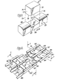
- Figure 5 shows diagrammatically a punch 75.
- This has a curved downwardly convex surface 76 on its lower end and. is movable vertically relative to an opposed shear tool 85 having curved upwardly convex surfaces 86 and 88 on the upoer end edges thereof and having a slot or relieved portion 87 formed therein into which punch 75 is moveable, against a spring loaded die anvil 89.
- End surfaces 72 and 73 on the punch 75 and surfaces 82 and 83 on the die anvil 85 lie substantially in spaced vertically disposed parallel shear planes 70.
- a pressure plate 92 has planar surfaces 91 extending along the whole of its length and separating adjacent apertures 90 in the plate, in which the punches 75 work.
- the width of the surfaces 91 is the same as the lateral width of the notchlforming cuts 14 in the strips.
- Longitudinal end walls of the aperture, adjacent which end faces of the punches can bear are provided by planar side surfaces of respective strongly spring loaded plungers 94. These are semi-cylindrical in shape. When projecting, they are proud of respective curved, concave, surfaces 93 formed in the plate 92 and aligned with the apertures. These surfaces 93 complement convex similar surfaces 86, 88 on the die or lower shear tool.
- the die anvil 89 is spring-loaded upwardly to a limit position at which its planar surface 81 is slightly above the uppermost line of the convex surfaces 86,88. It is also flush with uppermost plane surfaces 96 of stripper plungers 97, projecting beyond each corner of the die aperture 87.
- Stripper plungers 97 have an inclined nose surface portion 98 which extends to below the level of the uppermost line of the surfaces 86,88.
- the upper surfaces 96 of the stripper plungers and surface 91 of the die anvil provide a support platform upon which clip material is slidable, free of the punch or die of the shear tools, nose portions 98 offering a lead-in onto that platform.
- Stripper plungers 97, die anvil 89 and punch 75 are all driven in correlated movement, as will now be described with reference especially to Figure 7.
- the complete shear head 100 is driven between the jaws of a press (not shown) which act on upper 101 and lower 102 massive striker plates.
- the upper tool has a base plate 103 with which shear punches 75 are fast and from which they project.
- the base plate 103 is secured to the upper striker plate 101.
- the pressure plate 92 is strongly spring-loaded away from the base plate and guided for rectilinear motion by its engagement on the punches 75.
- Side arms 104 are secured to the base plate 103 to interact with the lower shear tool as will be described.
- the lower shear tool has a base plate 105 secured to the lower striker plate.
- a first cross-member 106 is spring loaded away from the base plate and guided for rectilinear movement by guide posts (not shown). The cross-member bears upon it, fast with it, the die anvils 89.
- a second cross-member 107 bears, fast with it, the stripper plungers 97 and also edge-guides 108 which have a surface exactly level with the top surfaces of the stripper plungers.
- the second cross-member 107 is spring loaded away from the first. It bears posts (not shown in the section of Figure 7) which are slidably borne within a die body part 110 which provides the surfaces 86 and 88.
- the posts have heads 109. These heads can be borne on by the portions 112 of the pressure platet 92.
- guide rods 111 Also on the body part 110 are guide rods 111 registering with apertures in the pressure plate 92 of the upper shear tool.
- datum lines X and Y refer respectively to the uppermost and lowermost levels of the surface 86,88.
- the increments could be other even multiples of the length of the clip.
- top pressure plate 92 is moved downwardly to engage the edges of the upper surface of strip 10 to prevent vertical motion of the strip relative to the plates, but not so tightly as to prevent lateral (horizontal) slippage of the strip between the upper and lower plates.
- Plungers 94 have strongly spring-loadedly engaged the material of the strip.
- the material of strip 10 will flatten under the influence of its own resilience and under the influence of the adjacent as yet unsheared next clip area, such that upper surfaces of clips 12a, 12b, and 12c will lie in a common plane, clip 12a being connected adjacent opposite indented edges of the strip by breaking portions 62 and 64 to the adjacent clips 12b and 12c.
- Forming the specific clip 12 illustrated in Figure 2 in accordance with the method hereinbefore described and diagrammatically illustrated in Figures 8 to 16 offers several important improvements over clip construction heretofore devised.
- the specific geometric configuration of the bag receiving passage 22 and central aperture 20, and particularly the provision of parallel surfaces 32,34,42 and 44, and surfaces 45 and 46 to form projections 47 and 48 allows a bag neck to be moved without obstruction into aperture 20 and permits the bag neck to expand and be gripped by projections 39, 40, 47 and 48. It is very important that an unobstructed path be provided through which a bag neck is moved for compressing the neck into the opening and to permit expansion of the bag neck after the clip has been attached.
- the method hereinbefore described for forming cut 60 allows connector portions 62 and 64 to be formed without stretching web 13 and strip 10 which is critical to precise positioning of one clip 12 relative to other clips 12 in a dispensing apparatus which fits clips to bag necks and which registers the clip actually being fitted by reference to the position of a clip some six or seven away along the strip.
- the length of line 60 can be controlled and adjusted to control force required for breaking portions 62 and 64 for removing a single clip. This feature is very important in that the specific material from which the clips will be formed is rendered less critical, since the length of cut line 60 can be adjusted to control breaking force of various materials.
- a maximum numbercf clips is formed from a strip of a given length thereby minimizing the size of a spool or roll of material which is used in a clip dispensing apparatus and, since the strip is planar and has little or no tendency to curl, tight and therefore eoonomical rolls can be formed.
- alternate punch and die pairs in an assembly such as is seen in Figure 7 are omitted and alternate longitudinally extending shear lines 52 are also omitted, thereby to obtain a strip of clips of the same individual width but doubled individual length, allowing more room for the attachment of price or other information.
- each clip being precisely formed and precisely positioned relative to each other clip in the strip to facilitate attachment of clips to bag necks, which means that the time for performing a cycle of operation of a clip attachment apparatus can be substantially reduced.
- the clips also have an improved central aperture configuration to facilitate attachment of a clip to a bag neck and to detachably lock the clip to the bag neck.
- the method which has been described involves portions of a strip of material adjacent opposite sides of a shear plane being moved to shear the material without moving edges of the material out of the vertical shear plane such that a plane of fracture is formed and the shear plane lies in the plane of fracture and such that no residue is separated from the strip when a clip is removed from the strip.
Landscapes
- Engineering & Computer Science (AREA)
- Mechanical Engineering (AREA)
- Life Sciences & Earth Sciences (AREA)
- Forests & Forestry (AREA)
- Making Paper Articles (AREA)
- Perforating, Stamping-Out Or Severing By Means Other Than Cutting (AREA)
Applications Claiming Priority (2)
| Application Number | Priority Date | Filing Date | Title |
|---|---|---|---|
| GB4843277 | 1977-11-21 | ||
| GB4843277 | 1977-11-21 |
Publications (3)
| Publication Number | Publication Date |
|---|---|
| EP0002132A2 true EP0002132A2 (fr) | 1979-05-30 |
| EP0002132A3 EP0002132A3 (en) | 1979-09-05 |
| EP0002132B1 EP0002132B1 (fr) | 1983-03-16 |
Family
ID=10448593
Family Applications (1)
| Application Number | Title | Priority Date | Filing Date |
|---|---|---|---|
| EP78300638A Expired EP0002132B1 (fr) | 1977-11-21 | 1978-11-17 | Procédé d'obtention de lignes de rupture dans une bande d'attaches |
Country Status (9)
| Country | Link |
|---|---|
| US (2) | US4215606A (fr) |
| EP (1) | EP0002132B1 (fr) |
| JP (1) | JPS5484676A (fr) |
| AU (1) | AU527944B2 (fr) |
| CA (1) | CA1110208A (fr) |
| DE (1) | DE2862203D1 (fr) |
| IL (1) | IL55974A (fr) |
| NZ (1) | NZ188947A (fr) |
| ZA (1) | ZA786503B (fr) |
Cited By (1)
| Publication number | Priority date | Publication date | Assignee | Title |
|---|---|---|---|---|
| WO2022020570A1 (fr) * | 2020-07-22 | 2022-01-27 | Bedford Industries, Inc. | Système et procédé de production de clips de fermeture de sacs |
Families Citing this family (45)
| Publication number | Priority date | Publication date | Assignee | Title |
|---|---|---|---|---|
| US4370936A (en) * | 1979-10-18 | 1983-02-01 | Midwestco, Inc. | Fabric tube forming methods and apparatus |
| US4413580A (en) * | 1979-10-18 | 1983-11-08 | Midwestco, Inc. | Method for forming fabric tubes |
| US4509231A (en) * | 1983-05-27 | 1985-04-09 | Paxton Jerre Hale | Dual-opening bag closure |
| US4630766A (en) * | 1983-06-01 | 1986-12-23 | Senco Products, Inc. | Fastener driving apparatus and methods and fastener supply |
| US4519285A (en) * | 1983-06-30 | 1985-05-28 | The Boeing Company | Cutting method and apparatus for tape laying machines |
| USD299434S (en) | 1985-11-07 | 1989-01-17 | Burford Corp. | Closure clip unit |
| US4911293A (en) * | 1989-02-10 | 1990-03-27 | Kwik Lok Corporation | Closure strip having offset protrusions |
| US4999969A (en) * | 1990-01-18 | 1991-03-19 | Kwik Lok Corporation | Bag closing apparatus |
| US5520281A (en) * | 1995-05-08 | 1996-05-28 | Huang; Chun-Yen | Product card of hooks |
| US6196042B1 (en) * | 1998-04-03 | 2001-03-06 | Tessera, Inc. | Coining tool and process of manufacturing same for making connection components |
| US6227365B1 (en) | 1998-06-19 | 2001-05-08 | Gary Products Group, Inc. | Molded product display system |
| US6601366B1 (en) | 2000-03-09 | 2003-08-05 | Burford Corporation | Tag insertion device for a bag tyer |
| US7281345B2 (en) * | 2004-02-04 | 2007-10-16 | Bedford Industries, Inc. | Merchandise labeling |
| US20060042051A1 (en) * | 2004-08-27 | 2006-03-02 | Irwin Jere F | Strips of clips and clip |
| US8261513B2 (en) * | 2004-11-02 | 2012-09-11 | Irwin Jere F | Apparatus and method for severing and loading bag fasteners |
| USD539140S1 (en) | 2005-04-27 | 2007-03-27 | Irwin Jere F | Strip of closure clips |
| CA2637049C (fr) * | 2006-01-17 | 2014-01-07 | Bedford Industries, Inc. | Articles d'etiquetage composites separables en forme de feuilles ou de rouleaux |
| US7836622B1 (en) * | 2006-09-28 | 2010-11-23 | Bedford Industries, Inc. | Foldable tag with expandable loop |
| US7763135B1 (en) | 2006-10-25 | 2010-07-27 | Bedford Industries, Inc. | Method for forming an elastic labeling band |
| WO2010080637A1 (fr) | 2008-12-18 | 2010-07-15 | C. R. Bard, Inc. | Guides d'aiguille pour dispositif d'imagerie échographique |
| US10863970B2 (en) | 2008-12-18 | 2020-12-15 | C. R. Bard, Inc. | Needle guide including enhanced visibility entrance |
| NZ600181A (en) | 2009-12-02 | 2014-05-30 | Bedford Ind Inc | Labeling article and manufacturing methods |
| US9974516B2 (en) * | 2010-12-22 | 2018-05-22 | C. R. Bard, Inc. | Selectable angle needle guide |
| US20120181197A1 (en) | 2011-01-17 | 2012-07-19 | Stafast Products, Inc. | Collated t-nut apparatus |
| KR20140040827A (ko) | 2011-06-23 | 2014-04-03 | 씨. 알. 바드, 인크. | 선택가능한 애스펙트를 가지는 바늘 안내부 |
| USD723621S1 (en) | 2012-11-09 | 2015-03-03 | Bedford Industries, Inc. | Elastomeric loop assembly |
| USD712154S1 (en) | 2012-11-21 | 2014-09-02 | Bedford Industries, Inc. | Tag-loop carrier assembly |
| US9481493B2 (en) | 2013-03-08 | 2016-11-01 | Joshua D. Vantrease | Interlock-able fingered closure clips |
| US9409737B2 (en) | 2013-03-08 | 2016-08-09 | Joshua D. Vantrease | Endless clip-strip feed splicer |
| US9481492B2 (en) | 2013-03-08 | 2016-11-01 | Joshua D. Vantrease | Interlock-able closure clips |
| USD707553S1 (en) * | 2013-03-08 | 2014-06-24 | Joshua Vantrease | Enclosure fastener |
| USD838780S1 (en) | 2016-06-13 | 2019-01-22 | Bedford Industries, Inc. | Elastic loop |
| US10388192B2 (en) | 2016-06-24 | 2019-08-20 | Bedford Industries, Inc. | Flat elastic labeling article |
| US10189588B2 (en) | 2016-07-07 | 2019-01-29 | Bedford Industries, Inc. | Bundling article with elastic loop and cooperating tag |
| US10723532B2 (en) | 2017-05-22 | 2020-07-28 | Bedford Insutries, Inc. | Elastic band package |
| US11021339B2 (en) | 2017-05-22 | 2021-06-01 | Bedford Industries, Inc. | Elastic band dispenser |
| US10607510B2 (en) | 2017-06-05 | 2020-03-31 | Bedford Industries, Inc. | Elastic band with embedded label |
| EP3768602A1 (fr) | 2018-03-20 | 2021-01-27 | Bedford Industries, Inc. | Article de fermeture à élément de fixation auxiliaire |
| US20190291101A1 (en) | 2018-03-23 | 2019-09-26 | Gourgen AMBARTSOUMIAN | Pcr tube holder |
| USD880296S1 (en) | 2018-09-25 | 2020-04-07 | Klr Systems Inc. | Bag closure clip |
| USD871212S1 (en) | 2018-09-25 | 2019-12-31 | Klr Systems Inc. | Bag closure clip |
| USD1005104S1 (en) * | 2019-09-27 | 2023-11-21 | Bedford Industries, Inc. | Closure roll |
| US12227326B2 (en) | 2021-10-21 | 2025-02-18 | Irwin Research And Development, Inc. | Closure strip guide and method |
| WO2024197272A2 (fr) | 2023-03-23 | 2024-09-26 | Pneu-Tools, Inc. | Système et procédé de moulage par rouleau continu, bande d'embout frangible et procédé de fabrication à l'aide d'un moulage par rouleau continu |
| USD1103764S1 (en) | 2023-09-22 | 2025-12-02 | Pneu-Tools, Inc. | Fastener cap |
Family Cites Families (18)
| Publication number | Priority date | Publication date | Assignee | Title |
|---|---|---|---|---|
| US2382143A (en) * | 1943-03-19 | 1945-08-14 | Us Envelope Co | String binder assemblage and package |
| US2350004A (en) * | 1943-03-20 | 1944-05-30 | Lawrence V Whistler | Punch and die mechanism for forming knockouts |
| US2382406A (en) * | 1943-11-11 | 1945-08-14 | Ralph E Engberg | Method and apparatus for dispensing gummed tape |
| US2721612A (en) * | 1951-04-09 | 1955-10-25 | American Can Co | Machine for feeding flimsy web material |
| GB685190A (en) | 1951-05-16 | 1952-12-31 | Leslie Gordon Forster | Improvements in or relating to means for cutting thin material |
| US2937464A (en) * | 1957-01-11 | 1960-05-24 | American Tag Company | Tag with fastening wire |
| GB883771A (en) | 1958-07-04 | 1961-12-06 | Evanco Engineering Company Wal | Improvements in and relating to securing devices for bags or like wrappings |
| GB880086A (en) * | 1959-05-20 | 1961-10-18 | Cornelius Johan Kruger | Improvements relating to metal fencing posts, spacers and the like |
| GB927047A (en) * | 1960-03-18 | 1963-05-22 | Victor Saville Talbot | Improvements in and relating to machinery for punching metal strip |
| US3164250A (en) * | 1963-11-22 | 1965-01-05 | Kwik Lok | Polystyrene multi-closure strip adapted for separation into individual closures |
| GB1260661A (en) | 1965-07-27 | 1972-01-19 | James Keith Macomber | Label feed |
| US3270874A (en) * | 1965-08-27 | 1966-09-06 | Kwik Lok | Polystyrene multi-closure strip scored for separation into individual closures |
| US3550246A (en) * | 1967-09-27 | 1970-12-29 | Standard Products Co | Rotary worm lance die and method for making continuous windlace core strip |
| US3548694A (en) * | 1969-01-16 | 1970-12-22 | American Tech Ind | Method and apparatus for slitting web material |
| UST911003I4 (en) | 1972-04-06 | 1973-06-05 | Granulation slitter | |
| GB1399906A (en) | 1972-11-06 | 1975-07-02 | Britt J P | Plastics strips |
| US3845682A (en) * | 1973-05-25 | 1974-11-05 | Procter & Gamble | Web perforating apparatus |
| US4026413A (en) * | 1973-11-02 | 1977-05-31 | John Philip Britt | Plastics strips |
-
1978
- 1978-11-06 US US05/957,672 patent/US4215606A/en not_active Expired - Lifetime
- 1978-11-17 JP JP14277378A patent/JPS5484676A/ja active Pending
- 1978-11-17 EP EP78300638A patent/EP0002132B1/fr not_active Expired
- 1978-11-17 DE DE7878300638T patent/DE2862203D1/de not_active Expired
- 1978-11-17 IL IL55974A patent/IL55974A/xx unknown
- 1978-11-20 ZA ZA00786503A patent/ZA786503B/xx unknown
- 1978-11-20 NZ NZ188947A patent/NZ188947A/xx unknown
- 1978-11-21 AU AU41763/78A patent/AU527944B2/en not_active Expired
- 1978-11-21 CA CA316,552A patent/CA1110208A/fr not_active Expired
-
1980
- 1980-05-09 US US06/148,259 patent/US4341303A/en not_active Expired - Lifetime
Cited By (1)
| Publication number | Priority date | Publication date | Assignee | Title |
|---|---|---|---|---|
| WO2022020570A1 (fr) * | 2020-07-22 | 2022-01-27 | Bedford Industries, Inc. | Système et procédé de production de clips de fermeture de sacs |
Also Published As
| Publication number | Publication date |
|---|---|
| EP0002132A3 (en) | 1979-09-05 |
| IL55974A0 (en) | 1979-01-31 |
| AU4176378A (en) | 1979-05-31 |
| ZA786503B (en) | 1979-10-31 |
| NZ188947A (en) | 1983-02-15 |
| IL55974A (en) | 1981-06-29 |
| AU527944B2 (en) | 1983-03-31 |
| EP0002132B1 (fr) | 1983-03-16 |
| DE2862203D1 (en) | 1983-04-21 |
| JPS5484676A (en) | 1979-07-05 |
| US4215606A (en) | 1980-08-05 |
| CA1110208A (fr) | 1981-10-06 |
| US4341303A (en) | 1982-07-27 |
Similar Documents
| Publication | Publication Date | Title |
|---|---|---|
| US4341303A (en) | Frangible strip of clips | |
| US3685251A (en) | Automatic packaging apparatus with improved means for cutting and contour trimming of packages | |
| US4026413A (en) | Plastics strips | |
| US3599318A (en) | Method of bonding sheets | |
| US3164249A (en) | Bag closures united in strip form | |
| US2409966A (en) | Blank for use in the manufacture of sliders for slide fasteners | |
| US3287195A (en) | Method of pressure welding thermoplastic film | |
| EP0162119A1 (fr) | Dispositif pour la fabrication d'un emballage à partir d'un flan plat | |
| WO1988009703A1 (fr) | Procede de pliage de couteau en bande | |
| EP0048807B1 (fr) | Procédé et appareil de fabrication d'une fermeture éclair contenant un fil conducteur | |
| US4435885A (en) | Process and apparatus for manufacturing storage battery plates | |
| US2221740A (en) | Manufacture of slide fastener elements | |
| US2299606A (en) | Method of making slide fasteners | |
| US3509990A (en) | Stack of joined thermoplastic sheets | |
| EP0068317B1 (fr) | Procédé et dispositif pour la fixation de matériau de renforcement sur bandes de fermetures éclair | |
| US2486941A (en) | Method of making slide fastener elements | |
| JP2558157B2 (ja) | 非円形断面を有する箱体の製造方法および製造装置 | |
| US4114218A (en) | Method of forming flat four-sided fastener parts having an opening therein | |
| CN213469264U (zh) | 自动推料冲压模具 | |
| US1558345A (en) | Die | |
| US3019833A (en) | Rolled edge metal containers, method and apparatus for making same | |
| US3643852A (en) | Nail chuck | |
| US2380440A (en) | Method of making fiber container parts | |
| US4077185A (en) | Apparatus for manufacturing and wrapping labels | |
| CA1163848A (fr) | Dispositif pour le raccordement reciproque d'une pluralite de feuilles souples |
Legal Events
| Date | Code | Title | Description |
|---|---|---|---|
| PUAI | Public reference made under article 153(3) epc to a published international application that has entered the european phase |
Free format text: ORIGINAL CODE: 0009012 |
|
| AK | Designated contracting states |
Designated state(s): DE FR GB SE |
|
| PUAL | Search report despatched |
Free format text: ORIGINAL CODE: 0009013 |
|
| AK | Designated contracting states |
Designated state(s): DE FR GB SE |
|
| 17P | Request for examination filed | ||
| GRAA | (expected) grant |
Free format text: ORIGINAL CODE: 0009210 |
|
| AK | Designated contracting states |
Designated state(s): DE FR GB SE |
|
| REF | Corresponds to: |
Ref document number: 2862203 Country of ref document: DE Date of ref document: 19830421 |
|
| ET | Fr: translation filed | ||
| PGFP | Annual fee paid to national office [announced via postgrant information from national office to epo] |
Ref country code: DE Payment date: 19831108 Year of fee payment: 6 |
|
| PGFP | Annual fee paid to national office [announced via postgrant information from national office to epo] |
Ref country code: FR Payment date: 19831123 Year of fee payment: 6 |
|
| PGFP | Annual fee paid to national office [announced via postgrant information from national office to epo] |
Ref country code: SE Payment date: 19831130 Year of fee payment: 6 |
|
| PG25 | Lapsed in a contracting state [announced via postgrant information from national office to epo] |
Ref country code: SE Effective date: 19841118 |
|
| GBPC | Gb: european patent ceased through non-payment of renewal fee | ||
| PG25 | Lapsed in a contracting state [announced via postgrant information from national office to epo] |
Ref country code: FR Free format text: LAPSE BECAUSE OF NON-PAYMENT OF DUE FEES Effective date: 19850731 |
|
| PG25 | Lapsed in a contracting state [announced via postgrant information from national office to epo] |
Ref country code: DE Effective date: 19850801 |
|
| REG | Reference to a national code |
Ref country code: FR Ref legal event code: ST |
|
| PG25 | Lapsed in a contracting state [announced via postgrant information from national office to epo] |
Ref country code: GB Effective date: 19881117 |
|
| EUG | Se: european patent has lapsed |
Ref document number: 78300638.0 Effective date: 19851008 |
|
| PLBE | No opposition filed within time limit |
Free format text: ORIGINAL CODE: 0009261 |
|
| STAA | Information on the status of an ep patent application or granted ep patent |
Free format text: STATUS: NO OPPOSITION FILED WITHIN TIME LIMIT |