EP0002377B1 - Ladeabschirmvorrichtung - Google Patents
Ladeabschirmvorrichtung Download PDFInfo
- Publication number
- EP0002377B1 EP0002377B1 EP78300731A EP78300731A EP0002377B1 EP 0002377 B1 EP0002377 B1 EP 0002377B1 EP 78300731 A EP78300731 A EP 78300731A EP 78300731 A EP78300731 A EP 78300731A EP 0002377 B1 EP0002377 B1 EP 0002377B1
- Authority
- EP
- European Patent Office
- Prior art keywords
- cover
- section
- hold
- chute
- loading
- Prior art date
- Legal status (The legal status is an assumption and is not a legal conclusion. Google has not performed a legal analysis and makes no representation as to the accuracy of the status listed.)
- Expired
Links
Images

Classifications
-
- B—PERFORMING OPERATIONS; TRANSPORTING
- B63—SHIPS OR OTHER WATERBORNE VESSELS; RELATED EQUIPMENT
- B63B—SHIPS OR OTHER WATERBORNE VESSELS; EQUIPMENT FOR SHIPPING
- B63B17/00—Vessels parts, details, or accessories, not otherwise provided for
- B63B17/02—Awnings, including rigid weather protection structures, e.g. sunroofs; Tarpaulins; Accessories for awnings or tarpaulins
- B63B17/023—Hatchway tents, e.g. for weather protection of cargo during loading or unloading
-
- B—PERFORMING OPERATIONS; TRANSPORTING
- B65—CONVEYING; PACKING; STORING; HANDLING THIN OR FILAMENTARY MATERIAL
- B65G—TRANSPORT OR STORAGE DEVICES, e.g. CONVEYORS FOR LOADING OR TIPPING, SHOP CONVEYOR SYSTEMS OR PNEUMATIC TUBE CONVEYORS
- B65G69/00—Auxiliary measures taken, or devices used, in connection with loading or unloading
Definitions
- the present invention relates to a loader and particularly to a cover which may be used to protect a bulk cargo as it is being fed to the hold of a ship.
- Bulk cargoes are generally fed from a loading arm direct into the hold of a ship through the open hatch cover so that both the cargo and the hold are exposed to the elements.
- This has two disadvantages, firstly it is necessary to stop loading during rain since water cannot generally be tolerated in either the hold or the cargo which is expensive since it means that a ship will be lying idle during the rain.
- powdered or granular cargoes such as fertilizer or grain considerably quantities of dust can be caused so polluting the atmosphere which can lead to loading being stopped. It has been proposed that ships' holds be covered during the loading of goods as, for example, in DE-B-1078004 but the flexible covers described therein are not adapted for use with a bulk cargo delivery chute and do not allow for relative movement of the loading arm and the ship.
- a cover which may be used to protect cargoes during loading so allowing loading to continue during wet weather and reducing the quantity of dust emitted into the surrounding environment.
- the present invention therefore provides a flexible cover (10, 15) for protecting material being delivered to the hold of a ship and including means (18) for attachment to the surrounds (17) of the hold of said ship, characterized in that, said cover includes means for attachment to a delivery chute (8, 9) of a loading arm (6, 7) and comprises two sections with the first section (10) being formed as a longitudinally extendable and contractable sleeve which surrounds the chute (8, 9) and the second section (15) extending from the chute (8, 9) towards the surrounds (17) of the hold.
- the cover of the present invention may be permanently attached to the loading arm whether the arm is in use or not or may be removed when the arm is not in use.
- the free end of the cover is attached to the surrounds of the hold of the ship when the caro is to be loaded. It is important, of course, that the cover be as light as possible consistent with the required strength so as not to put too great a strain on the loading arm. We have found that sailcloth and plastic sheeting are particularly useful materials.
- the method by which the cover is attached to the surrounds of the hold is not important and ropes have proved perfectly satisfactory. In wet weather the cover should, of course, be attached so as to prevent rain entering the hold but in dry weather significant dust prevention may be achieved without such stringent covering.
- Loading arms generally consist of a boom along which the material to be loaded is carried to a delivery head which delivers the material vertically downwards through a chute into the hold.
- the boom of the loader and the chute generally move up vertically in relation to the hold as the cargo rises in the hold.
- the cover of the present invention is therefore attached to the loading arm in such a way that the arm may move up and down without disturbing the protective effect of the cover by mounting the cover around the delivery chute of the loading arm with the section of the cover around the chute being extendable and contractable as, for example, in the form of a concertina.
- We have found that such a design also allows for small variations in the height of the ship relative to the loading arms due to tides and waves.
- the cover of the present invention allows such movement of the loading arm and chute without disturbing the protective effect of the cover.
- the cover be in two sections attached to each other but capable of moving independently of each other. The first section being attached around the chute as described above and the second being also mounted around the chute but capable of rotating relative to the axis of the chute and relative to the first section.
- the second section may be conveniently achieved by attaching the second section to a hoop fitted with wheels which run on a rail provided at the bottom of the said first section.
- the top of the second section may be rotatably mounted with respect to the bottom of the first section whilst the second section may extend from the bottom of said first section to cover the hold.
- the rail is inside rather than outside the first section to ensure that any water flowing down the outside of the first section flows onto the outside of the second section.
- Figure 1 shows the ship 1 having four holds 2, 3, 4 and 5 and Figure 2 is the section in the line AA of Figure 1 with the loader and cover in position over hold 2.
- the loader consists of a loader boom 6 leading to the loading cabin 7 from which is suspended the delivery chute 8 within its frame 9.
- the protective cover is in two parts, the first upper part 10 being connected at its top end 11 to the loading cabin, the lower end 12 being mounted on a ring 13 suspended between the delivery chute frame 9 and the cover 10 by wires 14.
- the lower part 15 of the cover is attached at its upper end to a ring 16 which is attached at its upper end to a ring 13 and thence to the loading cabin in such a way that the skirt at the bottom of upper portion 10 extends over the edge of the lower part 14 to give a water tight join.
- the remainder of the lower part 15 of the cover is then extended over the top of the hold 2 and attached to the surrounds of the hold 17 by any suitable means such as the springs 18.
- the wires 14 which support the rings 13 and 16 are mounted on pulleys which may be driven by the motor 19 so as to raise or lower the lower part 15 of the cover should this be necessary.
- the upper and lower parts of the cover 10 and 15 are connected to each other so that if the loading arm moves across the top of the hold. the two parts of the cover move with it in the same relationship to each other.
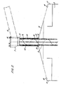
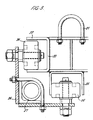
- Figure 3 illustrates a cross section through a circular ring system which can replace the two rings 13 and 16 of Figure 2 to allow relative rotation of the two parts of the cover.
- Figure 3 shows an upper ring 20 provided with a series of loops 21 around its circumference to which the supporting wires 14 (not shown) may be attached.
- the ring 20 being formed with outwardly and downwardly extending "U" shaped circumferential channels 22 and 23 which fit over rollers 24 and 25 mounted on the lower ring 26 which is provided with eyes 27 to which the lower part of the cover 15 may be attached.
Landscapes
- Engineering & Computer Science (AREA)
- Mechanical Engineering (AREA)
- Chemical & Material Sciences (AREA)
- Combustion & Propulsion (AREA)
- Ocean & Marine Engineering (AREA)
- Auxiliary Methods And Devices For Loading And Unloading (AREA)
- Materials For Medical Uses (AREA)
- Laminated Bodies (AREA)
Claims (5)
Applications Claiming Priority (2)
| Application Number | Priority Date | Filing Date | Title |
|---|---|---|---|
| GB5051377 | 1977-12-05 | ||
| GB5051377 | 1977-12-05 |
Publications (2)
| Publication Number | Publication Date |
|---|---|
| EP0002377A1 EP0002377A1 (de) | 1979-06-13 |
| EP0002377B1 true EP0002377B1 (de) | 1981-11-25 |
Family
ID=10456174
Family Applications (1)
| Application Number | Title | Priority Date | Filing Date |
|---|---|---|---|
| EP78300731A Expired EP0002377B1 (de) | 1977-12-05 | 1978-12-04 | Ladeabschirmvorrichtung |
Country Status (3)
| Country | Link |
|---|---|
| EP (1) | EP0002377B1 (de) |
| DE (1) | DE2861380D1 (de) |
| NO (1) | NO149303C (de) |
Cited By (2)
| Publication number | Priority date | Publication date | Assignee | Title |
|---|---|---|---|---|
| DE4118910A1 (de) * | 1991-06-08 | 1992-12-10 | Orenstein & Koppel Ag | Abdeckung fuer ladeluken |
| RU2762248C2 (ru) * | 2017-07-03 | 2021-12-16 | Вале С.А. | Устройство для выполнения погрузки на балкеры и способ погрузки |
Families Citing this family (5)
| Publication number | Priority date | Publication date | Assignee | Title |
|---|---|---|---|---|
| FR2457214A1 (fr) * | 1979-05-23 | 1980-12-19 | Phb Someral Sarl | Dispositif pour la protection des ouvertures de cales, pendant le chargement d'un navire |
| FR2531925A1 (fr) * | 1982-08-20 | 1984-02-24 | Phb Weserhuette Ag | Avant-toit pour elevateurs, tels que goulottes helicoidales et autres |
| AU616995B2 (en) * | 1988-08-19 | 1991-11-14 | Terry Hatziathanasiou | Multi width canopy for boats |
| BRPI1106767A2 (pt) * | 2011-08-17 | 2013-08-06 | Tmsa Tecnologia Em Movimentacao S A | dispositivo de proteÇço contra chuva para carregamento de material a granel em navio |
| US12208977B2 (en) * | 2020-01-15 | 2025-01-28 | Ihi Transport Machinery Co., Ltd | Rain-guard device for nozzle |
Family Cites Families (4)
| Publication number | Priority date | Publication date | Assignee | Title |
|---|---|---|---|---|
| DE1250291B (de) * | 1967-09-14 | |||
| DE661116C (de) * | 1935-12-24 | 1938-06-11 | Pohlig Akt Ges J | Vorrichtung zum UEberladen von staubendem Schuettgut |
| US2105589A (en) * | 1937-06-08 | 1938-01-18 | Read Machinery Company Inc | Hopper discharge apparatus |
| DE1078004B (de) * | 1956-07-16 | 1960-03-17 | Edward Alexander Sjoeman | Wasserdichte Abschirmvorrichtung zum Schutz von Guetern beim Laden und Loeschen, insbesondere auf Schiffen |
-
1978
- 1978-12-04 DE DE7878300731T patent/DE2861380D1/de not_active Expired
- 1978-12-04 NO NO784064A patent/NO149303C/no unknown
- 1978-12-04 EP EP78300731A patent/EP0002377B1/de not_active Expired
Cited By (2)
| Publication number | Priority date | Publication date | Assignee | Title |
|---|---|---|---|---|
| DE4118910A1 (de) * | 1991-06-08 | 1992-12-10 | Orenstein & Koppel Ag | Abdeckung fuer ladeluken |
| RU2762248C2 (ru) * | 2017-07-03 | 2021-12-16 | Вале С.А. | Устройство для выполнения погрузки на балкеры и способ погрузки |
Also Published As
| Publication number | Publication date |
|---|---|
| NO149303C (no) | 1984-03-28 |
| NO149303B (no) | 1983-12-19 |
| EP0002377A1 (de) | 1979-06-13 |
| NO784064L (no) | 1979-06-06 |
| DE2861380D1 (en) | 1982-01-28 |
Similar Documents
| Publication | Publication Date | Title |
|---|---|---|
| US5380058A (en) | Hold cover for a vehicle especially one for transporting particulate matter | |
| EP0002377B1 (de) | Ladeabschirmvorrichtung | |
| US8818586B2 (en) | Protection system for ship loading | |
| US20140331911A1 (en) | Device for providing protection against the rain, for loading bulk material on board a vessel | |
| US3509985A (en) | Conveyor loading and unloading apparatus | |
| JPS5823308B2 (ja) | エンチヨクコンベヤ | |
| US4224770A (en) | Outdoor grain pit cover | |
| US4329109A (en) | Vehicle lifting attachment | |
| US9650113B2 (en) | Cargo transporter loading assembly | |
| US5427491A (en) | Hatch cover for loading particulate matter | |
| WO2021059867A1 (ja) | 船積み用防風雨装置 | |
| SE9300832L (sv) | Anordning för i- och urlastning av fartyg | |
| US5778815A (en) | Ship hatch cover | |
| US5174075A (en) | Deformable sealing device for a gap between a wall opening of a building wall and a back wall of a vehicle | |
| IE47836B1 (en) | Loader cover | |
| CA1189476A (en) | Bulk-material unloading unit for ships or like carriers | |
| US3857499A (en) | Cargo handling equipment | |
| CA2699009A1 (en) | System and method for ship loading in all weather | |
| US4693360A (en) | Continuous operation bulk goods unloader | |
| SU1101376A1 (ru) | Укрытие люка судового трюма (его варианты) | |
| CA1339114C (en) | Bulk shipper for harbours and the like | |
| WO2019046920A1 (pt) | Cobertura para proteção contra chuva no carregamento de granéis em navios | |
| JP2025093783A (ja) | 荷役装置、防水シート | |
| SU101980A1 (ru) | Трюмный погрузчик дл навалочных грузов | |
| BR102018067874A2 (pt) | Cobertura para proteção contra chuva no carregamento de granéis em navios. |
Legal Events
| Date | Code | Title | Description |
|---|---|---|---|
| PUAI | Public reference made under article 153(3) epc to a published international application that has entered the european phase |
Free format text: ORIGINAL CODE: 0009012 |
|
| AK | Designated contracting states |
Designated state(s): BE DE FR GB NL |
|
| 17P | Request for examination filed | ||
| GRAA | (expected) grant |
Free format text: ORIGINAL CODE: 0009210 |
|
| AK | Designated contracting states |
Designated state(s): BE DE FR GB NL |
|
| REF | Corresponds to: |
Ref document number: 2861380 Country of ref document: DE Date of ref document: 19820128 |
|
| PGFP | Annual fee paid to national office [announced via postgrant information from national office to epo] |
Ref country code: FR Payment date: 19900918 Year of fee payment: 13 |
|
| PGFP | Annual fee paid to national office [announced via postgrant information from national office to epo] |
Ref country code: DE Payment date: 19900921 Year of fee payment: 13 |
|
| PGFP | Annual fee paid to national office [announced via postgrant information from national office to epo] |
Ref country code: BE Payment date: 19900926 Year of fee payment: 13 |
|
| PGFP | Annual fee paid to national office [announced via postgrant information from national office to epo] |
Ref country code: GB Payment date: 19901001 Year of fee payment: 13 |
|
| PGFP | Annual fee paid to national office [announced via postgrant information from national office to epo] |
Ref country code: NL Payment date: 19901231 Year of fee payment: 13 |
|
| PG25 | Lapsed in a contracting state [announced via postgrant information from national office to epo] |
Ref country code: GB Effective date: 19911204 |
|
| PG25 | Lapsed in a contracting state [announced via postgrant information from national office to epo] |
Ref country code: BE Effective date: 19911231 |
|
| BERE | Be: lapsed |
Owner name: EXXON RESEARCH AND ENGINEERING CY Effective date: 19911231 |
|
| PG25 | Lapsed in a contracting state [announced via postgrant information from national office to epo] |
Ref country code: NL Effective date: 19920701 |
|
| GBPC | Gb: european patent ceased through non-payment of renewal fee | ||
| NLV4 | Nl: lapsed or anulled due to non-payment of the annual fee | ||
| PG25 | Lapsed in a contracting state [announced via postgrant information from national office to epo] |
Ref country code: FR Effective date: 19920831 |
|
| PG25 | Lapsed in a contracting state [announced via postgrant information from national office to epo] |
Ref country code: DE Effective date: 19920901 |
|
| REG | Reference to a national code |
Ref country code: FR Ref legal event code: ST |
|
| PLBE | No opposition filed within time limit |
Free format text: ORIGINAL CODE: 0009261 |
|
| STAA | Information on the status of an ep patent application or granted ep patent |
Free format text: STATUS: NO OPPOSITION FILED WITHIN TIME LIMIT |