EP0002839A1 - Procédé pour chauffer des locaux et application de ce procédé pour le chauffage d'un bâtiment - Google Patents
Procédé pour chauffer des locaux et application de ce procédé pour le chauffage d'un bâtiment Download PDFInfo
- Publication number
- EP0002839A1 EP0002839A1 EP78101878A EP78101878A EP0002839A1 EP 0002839 A1 EP0002839 A1 EP 0002839A1 EP 78101878 A EP78101878 A EP 78101878A EP 78101878 A EP78101878 A EP 78101878A EP 0002839 A1 EP0002839 A1 EP 0002839A1
- Authority
- EP
- European Patent Office
- Prior art keywords
- heat
- wall
- building
- heat exchanger
- building according
- Prior art date
- Legal status (The legal status is an assumption and is not a legal conclusion. Google has not performed a legal analysis and makes no representation as to the accuracy of the status listed.)
- Withdrawn
Links
- 238000000034 method Methods 0.000 title claims description 20
- 238000010438 heat treatment Methods 0.000 claims abstract description 19
- 239000002609 medium Substances 0.000 claims description 21
- 238000009413 insulation Methods 0.000 claims description 18
- 238000003860 storage Methods 0.000 claims description 18
- XLYOFNOQVPJJNP-UHFFFAOYSA-N water Substances O XLYOFNOQVPJJNP-UHFFFAOYSA-N 0.000 claims description 16
- 238000002156 mixing Methods 0.000 claims description 7
- 238000010521 absorption reaction Methods 0.000 claims description 5
- 238000001704 evaporation Methods 0.000 claims description 5
- 230000008020 evaporation Effects 0.000 claims description 5
- 239000006163 transport media Substances 0.000 claims description 5
- 238000002360 preparation method Methods 0.000 claims description 4
- 239000004698 Polyethylene Substances 0.000 claims description 3
- 239000011505 plaster Substances 0.000 claims description 3
- 230000002528 anti-freeze Effects 0.000 claims description 2
- 230000006835 compression Effects 0.000 claims description 2
- 238000007906 compression Methods 0.000 claims description 2
- 239000000284 extract Substances 0.000 claims description 2
- -1 polyethylene Polymers 0.000 claims description 2
- 229920000573 polyethylene Polymers 0.000 claims description 2
- 238000005496 tempering Methods 0.000 claims description 2
- 238000011144 upstream manufacturing Methods 0.000 claims description 2
- 239000012072 active phase Substances 0.000 claims 1
- 239000007792 gaseous phase Substances 0.000 claims 1
- 230000005855 radiation Effects 0.000 description 11
- 230000008901 benefit Effects 0.000 description 8
- 238000001816 cooling Methods 0.000 description 8
- 230000000694 effects Effects 0.000 description 5
- 238000005338 heat storage Methods 0.000 description 4
- 230000007613 environmental effect Effects 0.000 description 3
- 239000004793 Polystyrene Substances 0.000 description 2
- 230000002349 favourable effect Effects 0.000 description 2
- 238000010304 firing Methods 0.000 description 2
- 239000006260 foam Substances 0.000 description 2
- 239000008236 heating water Substances 0.000 description 2
- 230000007704 transition Effects 0.000 description 2
- 108010053481 Antifreeze Proteins Proteins 0.000 description 1
- 229920005830 Polyurethane Foam Polymers 0.000 description 1
- 229910000746 Structural steel Inorganic materials 0.000 description 1
- XRWSZZJLZRKHHD-WVWIJVSJSA-N asunaprevir Chemical compound O=C([C@@H]1C[C@H](CN1C(=O)[C@@H](NC(=O)OC(C)(C)C)C(C)(C)C)OC1=NC=C(C2=CC=C(Cl)C=C21)OC)N[C@]1(C(=O)NS(=O)(=O)C2CC2)C[C@H]1C=C XRWSZZJLZRKHHD-WVWIJVSJSA-N 0.000 description 1
- TZCXTZWJZNENPQ-UHFFFAOYSA-L barium sulfate Chemical compound [Ba+2].[O-]S([O-])(=O)=O TZCXTZWJZNENPQ-UHFFFAOYSA-L 0.000 description 1
- 230000008859 change Effects 0.000 description 1
- 239000003795 chemical substances by application Substances 0.000 description 1
- 230000000052 comparative effect Effects 0.000 description 1
- 229940125961 compound 24 Drugs 0.000 description 1
- 238000009833 condensation Methods 0.000 description 1
- 230000005494 condensation Effects 0.000 description 1
- 238000010276 construction Methods 0.000 description 1
- 238000010586 diagram Methods 0.000 description 1
- 238000009792 diffusion process Methods 0.000 description 1
- 238000009826 distribution Methods 0.000 description 1
- 230000005611 electricity Effects 0.000 description 1
- 238000004146 energy storage Methods 0.000 description 1
- 238000000605 extraction Methods 0.000 description 1
- 230000006870 function Effects 0.000 description 1
- 239000003673 groundwater Substances 0.000 description 1
- 230000001771 impaired effect Effects 0.000 description 1
- 238000009434 installation Methods 0.000 description 1
- 239000007788 liquid Substances 0.000 description 1
- 238000004519 manufacturing process Methods 0.000 description 1
- 230000010363 phase shift Effects 0.000 description 1
- 229920002223 polystyrene Polymers 0.000 description 1
- 229920002635 polyurethane Polymers 0.000 description 1
- 239000004814 polyurethane Substances 0.000 description 1
- 239000011496 polyurethane foam Substances 0.000 description 1
- 230000009467 reduction Effects 0.000 description 1
- 230000002787 reinforcement Effects 0.000 description 1
- 239000002689 soil Substances 0.000 description 1
- 210000002023 somite Anatomy 0.000 description 1
- 239000000126 substance Substances 0.000 description 1
- 230000002123 temporal effect Effects 0.000 description 1
- 208000008918 voyeurism Diseases 0.000 description 1
Images


Classifications
-
- F—MECHANICAL ENGINEERING; LIGHTING; HEATING; WEAPONS; BLASTING
- F24—HEATING; RANGES; VENTILATING
- F24D—DOMESTIC- OR SPACE-HEATING SYSTEMS, e.g. CENTRAL HEATING SYSTEMS; DOMESTIC HOT-WATER SUPPLY SYSTEMS; ELEMENTS OR COMPONENTS THEREFOR
- F24D11/00—Central heating systems using heat accumulated in storage masses
- F24D11/02—Central heating systems using heat accumulated in storage masses using heat pumps
-
- F—MECHANICAL ENGINEERING; LIGHTING; HEATING; WEAPONS; BLASTING
- F24—HEATING; RANGES; VENTILATING
- F24D—DOMESTIC- OR SPACE-HEATING SYSTEMS, e.g. CENTRAL HEATING SYSTEMS; DOMESTIC HOT-WATER SUPPLY SYSTEMS; ELEMENTS OR COMPONENTS THEREFOR
- F24D11/00—Central heating systems using heat accumulated in storage masses
- F24D11/02—Central heating systems using heat accumulated in storage masses using heat pumps
- F24D11/0214—Central heating systems using heat accumulated in storage masses using heat pumps water heating system
- F24D11/0221—Central heating systems using heat accumulated in storage masses using heat pumps water heating system combined with solar energy
-
- F—MECHANICAL ENGINEERING; LIGHTING; HEATING; WEAPONS; BLASTING
- F24—HEATING; RANGES; VENTILATING
- F24S—SOLAR HEAT COLLECTORS; SOLAR HEAT SYSTEMS
- F24S20/00—Solar heat collectors specially adapted for particular uses or environments
- F24S20/60—Solar heat collectors integrated in fixed constructions, e.g. in buildings
- F24S20/66—Solar heat collectors integrated in fixed constructions, e.g. in buildings in the form of facade constructions, e.g. wall constructions
-
- F—MECHANICAL ENGINEERING; LIGHTING; HEATING; WEAPONS; BLASTING
- F25—REFRIGERATION OR COOLING; COMBINED HEATING AND REFRIGERATION SYSTEMS; HEAT PUMP SYSTEMS; MANUFACTURE OR STORAGE OF ICE; LIQUEFACTION SOLIDIFICATION OF GASES
- F25B—REFRIGERATION MACHINES, PLANTS OR SYSTEMS; COMBINED HEATING AND REFRIGERATION SYSTEMS; HEAT PUMP SYSTEMS
- F25B30/00—Heat pumps
- F25B30/02—Heat pumps of the compression type
-
- Y—GENERAL TAGGING OF NEW TECHNOLOGICAL DEVELOPMENTS; GENERAL TAGGING OF CROSS-SECTIONAL TECHNOLOGIES SPANNING OVER SEVERAL SECTIONS OF THE IPC; TECHNICAL SUBJECTS COVERED BY FORMER USPC CROSS-REFERENCE ART COLLECTIONS [XRACs] AND DIGESTS
- Y02—TECHNOLOGIES OR APPLICATIONS FOR MITIGATION OR ADAPTATION AGAINST CLIMATE CHANGE
- Y02B—CLIMATE CHANGE MITIGATION TECHNOLOGIES RELATED TO BUILDINGS, e.g. HOUSING, HOUSE APPLIANCES OR RELATED END-USER APPLICATIONS
- Y02B10/00—Integration of renewable energy sources in buildings
- Y02B10/20—Solar thermal
-
- Y—GENERAL TAGGING OF NEW TECHNOLOGICAL DEVELOPMENTS; GENERAL TAGGING OF CROSS-SECTIONAL TECHNOLOGIES SPANNING OVER SEVERAL SECTIONS OF THE IPC; TECHNICAL SUBJECTS COVERED BY FORMER USPC CROSS-REFERENCE ART COLLECTIONS [XRACs] AND DIGESTS
- Y02—TECHNOLOGIES OR APPLICATIONS FOR MITIGATION OR ADAPTATION AGAINST CLIMATE CHANGE
- Y02B—CLIMATE CHANGE MITIGATION TECHNOLOGIES RELATED TO BUILDINGS, e.g. HOUSING, HOUSE APPLIANCES OR RELATED END-USER APPLICATIONS
- Y02B10/00—Integration of renewable energy sources in buildings
- Y02B10/70—Hybrid systems, e.g. uninterruptible or back-up power supplies integrating renewable energies
-
- Y—GENERAL TAGGING OF NEW TECHNOLOGICAL DEVELOPMENTS; GENERAL TAGGING OF CROSS-SECTIONAL TECHNOLOGIES SPANNING OVER SEVERAL SECTIONS OF THE IPC; TECHNICAL SUBJECTS COVERED BY FORMER USPC CROSS-REFERENCE ART COLLECTIONS [XRACs] AND DIGESTS
- Y02—TECHNOLOGIES OR APPLICATIONS FOR MITIGATION OR ADAPTATION AGAINST CLIMATE CHANGE
- Y02E—REDUCTION OF GREENHOUSE GAS [GHG] EMISSIONS, RELATED TO ENERGY GENERATION, TRANSMISSION OR DISTRIBUTION
- Y02E10/00—Energy generation through renewable energy sources
- Y02E10/40—Solar thermal energy, e.g. solar towers
Definitions
- the invention relates to a method for room temperature control using at least one heat pump, by means of which the thermal energy extracted from a body by means of a liquid medium is supplied to at least one store after it has been upgraded or depreciated, and is withdrawn therefrom for room temperature control.
- a disadvantage of this known heating method is that heat pumps are often unable to cope with the large temperature difference required. For this reason, such heating systems are usually supplemented by a conventional heating system, so that a double heating system (bivalent system) is produced for energy generation, the conventional heating system being at the peak demand Heat covers.
- Another disadvantage is that, if one of the energy sources fails, such bivalent systems are either no longer fully functional or, if the electrical power fails, the heat pump also fails.
- the present invention has for its object to provide a method of the type described above, which avoids the disadvantages of the known heating systems using heat pumps.
- the invention provides that the building mass surrounding the room to be temperature-controlled is used as the storage.
- the inventive method with an average water temperature of only 24 ° allows to 28 o C to fahren.Dies is achieved not least by increasing the radiating surface by referring to the building ground.
- Another important advantage of the invention is that no radiators are required to heat rooms. Likewise, a heat storage tank for heating water can be used to be dispensed with.
- the method according to the invention thus makes it possible to completely dispense with the conventional bivalence system for heating rooms, so that emissions do not occur.
- a conventional emergency power generator can be switched on to supply it in an emergency, so that an uninterrupted heat supply is guaranteed.
- the storage capacity of the heating process is so large that only a fraction of the temperature reduction takes place in the same time period in comparison with the conventional heating methods.
- the body to be used as the supplier of the heat energy can be of various forms, for example the heat energy can be extracted from the earth or from groundwater or from a river, but this requires an appropriate area that offers the possibility of heat extraction.
- a special feature of the invention can be seen in the fact that the body is integrated into the building mass in order to withdraw the thermal energy. This measure has the advantage that no special area is required.
- the building mass As from an inexhaustible source of energy, the radiation of diffuse radiation, direct radiation and atmospheric radiation from the surroundings of the building mass can be absorbed on its surface. Energy becomes beyond this radiation taken, the heat radiation from the environment is used, which has its maximum in the infrared range. This energy source is mainly used at night. Even with a large temperature difference between the inner and outer mass, the heat gain from the outside outweighs the heat loss of the inner building mass by a suitable one Insulation from the outside many times over.
- Another object of the invention is a building that can be heated using at least one room cell using the method according to the invention a pipe system formed heat exchanger is included.
- a preferred construction provides that the building wall is double-walled, that the outer wall forms the body for the removal of the thermal energy and is provided at a distance from the inner wall and that the space between the two walls is filled with a full-surface heat and moisture insulation.
- the inner wall takes on the task of stability and heat storage for room temperature control.
- the outer wall fulfills the task of absorbing energy from the environment and storing it. Both walls, as already indicated above, are stripped with regard to heat flow and water vapor diffusion.
- the outer wall assumes the temperature of the environment, while the inner wall strives for the inside temperature of the building up to the insulation.
- the insulation prevents heat transfer between the two walls.
- the surface area for absorbing the energy radiation can be enlarged in a relatively simple manner, for example by applying a special energy absorption plaster, the structure of which can be deliberately designed for the infrared range in order to increase the heat absorption
- a special energy absorption plaster the structure of which can be deliberately designed for the infrared range in order to increase the heat absorption
- At least the floor of at least one room cell in the building that is to be temperature-controlled and acts as a storage tank can be heated by a heat exchanger that can be connected to the heat pump, in particular designed as a piping system Design a ceiling that can be heated, with the possibility, especially in the cold season, of switching the heat exchangers in the individual room boundary walls in series, which creates an ideal temperature profile in all rooms, which ensures unmatched comfort.
- Each room cell is preferably temperature-controllable by its own, in particular controllable, heat exchanger system. This makes it possible to keep the individual room cells at different room temperatures, depending on the individual request, although the building mass surrounding the room cells forms the heat store.
- the two heat exchanger systems of the outer and inner walls can be connected directly to one another when the heat pump is bypassed.
- This measure has the advantage that during the transition period with direct solar radiation the temperature of the storage mass of the outer wall exceeds that The peaks of this temperature amplitude can be controlled via a temperature difference valve and delivered directly to the inner storage masses as long as the heat transfer medium circulates between the two masses.
- the heat gain can be used for the cool evening and night hours without the heat pump being required During the evening chill, additional, in particular free, temperature control of the room cell is available.
- the method according to the invention also offers very special advantages in summer if, instead of heating, cooling of room cells is desired, namely if the outer wall is short-circuited bypassing the heat pump, the lowest temperature value of the day-night temperature amplitude of the cool night and If the circulation is maintained during the night and interrupted during the day, functional cooling is guaranteed free of charge.
- the building can be removed tion can be made even more advantageous by flowing cooling energy from the soil above the foundation surface into the building masses of the foundations.
- valve device for example a four-way valve, even enables active cooling by the heat pump, in that the evaporator of the heat pump extracts the heat energy from the internal building masses, so that only pleasant radiation energy is used according to the temperature
- unpleasant cooling fans can be dispensed with.
- a control device for controlling the flow rate of the medium in the outer wall as a function of the temperature uptake of various outer wall parts occurs, the flow of the medium is greatest, so that a good use of the heat absorbed by the outer wall from the environment is possible.
- Temperatures of approx. 40 0 to 45 ° C are required for hot water preparation.
- the medium temperature generated by the heat pump of approximately 26 ° C which is sufficient for heating the building, cannot be used for heating domestic hot water.
- a second heat pump could be used for this used which cut off the heating circuit of the first heat pump heat and output side heat at a temperature level of 40 ° to 45 0 C gives off invention when a heat pump is used also avoids here such a complicated and inefficient means, wherein as a preliminary stage of their liquefier a preheat exchanger is connected upstream to remove the superheating heat of the evaporation medium to heat a custom water storage.
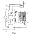
- the building shown has an inner structure 18 containing a plurality of room cells 1 0 , 12, 14, 16, which is preferably made of concrete.
- This structure is preferably completely surrounded by an outer skin 20, an intermediate space 22 being contained between the structure and the outer skin , which is completely filled with an insulating compound 24.
- the insulation can be made of polyurethane hard, for example consist of foam.
- a roof covering the structure is designated as a whole by 26. Also to this roof, the structure is insulated by insulation 28. Furthermore, structure 18 is insulated from the foundations 3o and basement by insulation 32. Thus, the inner structure 18 is isolated from the The outer skin or the foundations are completely enclosed.
- a heat exchanger system 34 is inserted, to the inflow and outflow lines of which are designated 36 and 38. To clarify the circuit of the medium serving as heat transfer medium, these lines are shown outside the entire structure. Also between the roof covering and the Insulation 28 arranged a heat exchanger system 34.
- each room cell is assigned an internal heat exchanger system 40 contained in the structure 18, which are connected via an inflow line 42 and an outflow line 44 to at least one heat pump 46.
- the inflow and outflow lines 36, 38 are connected to this heat pump Heat exchanger system 48 is contained in the foundation of the building, which can be connected to the line 38 supplying the thermal energy via a valve 50.
- the desired room temperature in the individual room cells can be preselected and kept constant by means of thermostats 52, which can either be provided in the relevant room cell or can be combined to form a common switching arrangement, the heat sensors of which are arranged in the return line 44 and change the corresponding selection Flow rate in the relevant exchange system of the room cell, i.e. the inflow line 42.
- the room cell 16 is provided as an installation space for the heat pump 46, but for reasons of Uber visibility is shown outside the building.
- This heat pump is connected to a hot water tank 54 for producing hot domestic water. It has an evaporator 56, a compressor 58 and a condenser 6 0 .
- a preheater 62 is interposed between the compressor 58 and the condenser 6o, through which superheating heat is removed from the evaporation medium of the heat pump and fed to the hot water tank 54.
- the outer surface of the outer skin 2o is provided with a special energy absorption plaster 64 with a layer thickness of preferably 4 to 6 mm, which is highly structured.
- the frost-protected circuit of the heat transfer medium takes heat from the outer skin, which is stored on its surface by the environmental energy by irradiation, and brings this via line 38 into the evaporator 56 of the heat pump 46.
- the heated return flows back into the heat exchanger system 34 of the outer skin 2o With colder temperature level, again ready to take in, which closes the cycle of energy production.
- the energy gain is taken up by evaporation of the evaporation medium of the heat pump, its temperature is increased by the compression work of the compressor 58 and then released to the warm circuit of the internal heat exchanger system 4o by liquefaction the superheat is through the preheater 62 which heats the carrier medium for the hot water preparation.
- the building body storage masses are connected to the condenser 6o of the heat pump via the inflow line 42 and the return line 44, which are stored, for example, at 22 ° to 26 ° C.
- the heat is given off to the interior of the room cells by heat radiation and slight convection flow. In winter, the distribution is preferably such that the floor, the walls and the ceilings are connected in series, which creates an ideal temperature profile in all rooms.
- the walls of the ground floor and the gable walls of the attic were double-shelled, and on the south side of the roof, heat exchanger pipes were laid on a roof area of approx. 9o m 2 for energy generation
- the wall thickness of the concrete wall forming the outer skin 2o was 12 cm and the wall thickness of the concrete walls forming the inner structure 18 was 14 cm.
- the wall thickness of the between the outer skin 2o and the inner structure 18 arranged insulation layer 24 was 10 cm.
- polyurethane foam sheets can also be used.
- the heat exchanger tubes 34 and 40 respectively, which were concreted into the outer skin 2o and the inner structure 18, were designed as flexible polyethylene tubes The course is laid on a common level, with a leading and a continuing spiral. This ensures that a uniform temperature level is achieved in the exchanger area over the entire exchanger area. Normally, about 6-7m PE pipe is installed per m 2 wall area and that twice the length in the walls of the bathroom.
- the levels in which the exchanger pipes 34 and 40o of the outer skin 20o and the inner structure 18 were laid lie on both sides of the insulation layer 24 in the immediate vicinity thereof.
- the distance of the heat exchanger pipes from the insulation layer is approximately equal to the diameter of the heat exchanger tubes 34 and 40, respectively, which have an outer diameter of 20 mm and an inner diameter of 16 mm. They are each fastened to the side of a structural steel mat facing the insulating layer 24, which at the same time forms the reinforcement for the outer skin 20 or the walls of the inner structural body 18.
- the exchanger tubes 34 of the outer skin 2o are arranged at the greatest possible distance from the surface of the outer skin 2o facing the building environment, via which the environmental heat is absorbed.
- the exchanger tubes 4o of the inner building walls 18 are arranged at the greatest possible distance from that surface of the inner walls , through which the heat is given off to the interior of the building, which, viewed across the wall cross-section, creates an optimal temperature profile for energy absorption and dissipation.
- the heat pump and the heat exchangers 34 and 4o coupled to it are controlled via a temperature detector in the return of the heat exchanger 4o of the inner building wall 18. If the return temperature drops below an adjustable value of, for example, 21 ° C, the heat pump 46 is activated as long as the heat pump 46 works, the flow temperature in the heat exchanger 4o of the building's inner wall 18 is approx. 28 C.
- the return flow changes The temperature at the inner surface 18 and the temperature profile of the inner surface 18 and the layer facing the insulation layer 24, in which the heat exchanger tubes 4o are laid, towards the side facing the interior, the temperature on the inner surface changes only slightly and approximately to the same extent as the return temperature recorded by means of the temperature detector, so that this is directly a measure of the room temperature in the building.
- the favorable property of the building according to the invention resulting from the storage effect of the outer skin 2o is also that a cooling thereof resulting from the removal of heat from this storage takes place practically only on its side facing the insulation layer 24, while the temperature on the outer surface of this storage remains practically the same as the environmental temperature This will prevent the exterior surface of the building from icing up.
- FIG 3 shows a particularly advantageous connection of the heat exchanger 34 arranged in the outer wall mass 2o and of the heat exchanger 48 arranged in the foundation mass 3o with the heat pump 46.
- these heat exchangers 34 and 48 only one exchanger unit is shown. A plurality of such units can be used in each case Exchanger units 34 and 48 are provided, which are connected in parallel.
- the return lines 38 and 71 of the exchanger units 34 and 48 are coupled to one another via a mixing valve 72. From this mixing valve 72, a common heat transport line 74 leads to the evaporator 56 of the heat pump 46. from which the coupled-in heat is removed in the evaporator 56 flows back via the return line 73 to the heat exchangers 34 and 48.
- this mixing ratio is 1: 1.
Landscapes
- Engineering & Computer Science (AREA)
- Thermal Sciences (AREA)
- General Engineering & Computer Science (AREA)
- Mechanical Engineering (AREA)
- Physics & Mathematics (AREA)
- Chemical & Material Sciences (AREA)
- Combustion & Propulsion (AREA)
- Sustainable Energy (AREA)
- Sustainable Development (AREA)
- Life Sciences & Earth Sciences (AREA)
- Building Environments (AREA)
- Steam Or Hot-Water Central Heating Systems (AREA)
- Other Air-Conditioning Systems (AREA)
Applications Claiming Priority (2)
| Application Number | Priority Date | Filing Date | Title |
|---|---|---|---|
| DE2759181 | 1977-12-31 | ||
| DE19772759181 DE2759181A1 (de) | 1977-12-31 | 1977-12-31 | Verfahren zur raumtemperierung sowie nach diesem verfahren zu beheizendes gebaeude |
Publications (1)
| Publication Number | Publication Date |
|---|---|
| EP0002839A1 true EP0002839A1 (fr) | 1979-07-11 |
Family
ID=6027881
Family Applications (1)
| Application Number | Title | Priority Date | Filing Date |
|---|---|---|---|
| EP78101878A Withdrawn EP0002839A1 (fr) | 1977-12-31 | 1978-12-29 | Procédé pour chauffer des locaux et application de ce procédé pour le chauffage d'un bâtiment |
Country Status (7)
| Country | Link |
|---|---|
| EP (1) | EP0002839A1 (fr) |
| JP (1) | JPS54132344A (fr) |
| BE (1) | BE873103A (fr) |
| BR (1) | BR7808583A (fr) |
| DE (1) | DE2759181A1 (fr) |
| FR (1) | FR2413615A1 (fr) |
| GB (1) | GB2014297A (fr) |
Cited By (24)
| Publication number | Priority date | Publication date | Assignee | Title |
|---|---|---|---|---|
| FR2461900A1 (fr) * | 1979-07-19 | 1981-02-06 | Feist Artus | Installation d'isolation thermique et captage d'energie thermique pour un batiment |
| EP0032381A1 (fr) * | 1980-01-10 | 1981-07-22 | Meinrad Grammer | Installation de captage de l'énergie ambiante |
| DE3022521A1 (de) * | 1980-06-16 | 1981-12-24 | Johann B. 6530 Bingen Pfeifer | Luftkollektor fuer eine waermepumpenanlage o.dgl. |
| EP0045506A1 (fr) * | 1980-08-04 | 1982-02-10 | Johann B. Pfeifer | Installation d'une pompe à chaleur pour l'enlèvement de chaleur de l'atmosphère |
| DE3026638A1 (de) * | 1980-07-14 | 1982-02-11 | Frankipfahl-Baugesellschaft mbH, 4000 Düsseldorf | In das erdreich einzubringender waermetauscherkoerper |
| EP0048385A3 (en) * | 1980-09-20 | 1982-05-26 | Karl Seemann | Arrangement for the absorption and storage of environmental heat for the heating and cooling of structures |
| DE3103877A1 (de) * | 1981-02-05 | 1982-08-12 | Baustoffwerke Rasselstein Gmbh, 5450 Neuwied | Gebaeude mit waermerueckgewinnungsanlage |
| DE3103173A1 (de) * | 1981-01-30 | 1982-08-26 | Johann B. 6530 Bingen Pfeifer | Waermemaschine zur aufnahme von waerme aus der umgebungsatmosphaere |
| FR2500602A1 (fr) * | 1981-02-26 | 1982-08-27 | Lemasson Jean Pierre | Installation de transfert de chaleur compacte |
| DE3132757A1 (de) * | 1981-08-19 | 1983-03-03 | Horst 7900 Ulm Glaser | Verfahren und anordnung zum gewinnen von heiz- und/oder kuehlenergie aus der umwelt |
| FR2514876A1 (fr) * | 1981-10-21 | 1983-04-22 | Gimenez Christian | Isolation thermique dynamique thermodynamique a fluides paralleles |
| FR2546552A1 (fr) * | 1983-05-25 | 1984-11-30 | Solefil | Enveloppe a paroi multiple isolee thermiquement et munie de moyens de recuperation d'energie solaire pour delimiter au moins en partie un volume habitable |
| EP0115014A3 (en) * | 1982-12-30 | 1985-09-18 | Johannes Dr.-Ing. Schmitz | Method of saving energy while controlling the air temperature in buildings, and building therefor |
| DE3600230A1 (de) * | 1986-01-07 | 1987-07-09 | Mero Werke Kg | Waermegewinnungsanlage zur nutzbarmachung von erdwaerme z.b. zur gebaeudeheizung |
| FR2623888A1 (fr) * | 1987-12-01 | 1989-06-02 | Scheu Walter | Installation pour prelever et emmagasiner de la chaleur du milieu ambiant |
| DE3911297A1 (de) * | 1988-04-13 | 1989-10-26 | Ripp Energiesysteme Gmbh | Beheizung von gebaeuden durch kontinuierlich rezirkulierende waerme und waermepumpe |
| DE10054607A1 (de) * | 2000-11-03 | 2002-05-08 | Hochtief Fertigteilbau Gmbh | Niedrigenergiegebäude |
| WO2003010469A1 (fr) * | 2001-07-26 | 2003-02-06 | Entech Energie Management Ag | Installation et procede d'alimentation de consommateurs en energie thermique ou energie frigorifique |
| DE102010023762A1 (de) * | 2010-06-15 | 2011-12-15 | Rolf Smitka | Vorrichtung zur Regelung des Durchflusses eines Wärmeübertragungsmediums |
| DE202010015516U1 (de) * | 2010-11-15 | 2012-02-29 | Uponor Innovation Ab | Regelungsvorrichtung für eine Heizungsanlage und Heizungsanlage |
| EP2478301B1 (fr) * | 2009-09-14 | 2017-05-10 | STP S.r.L. | Système de recouvrement pour chauffer/refroidir des pièces et isoler thermiquement et acoustiquement des espaces fixes entourés verticalement |
| WO2017158100A1 (fr) * | 2016-03-18 | 2017-09-21 | Ats Advanced Thermo Solutions Ag | Système de thermorégulation d'un bâtiment ainsi que procédé de thermorégulation d'un bâtiment utilisant un système de ce type |
| CN112484188A (zh) * | 2020-12-11 | 2021-03-12 | 广东海洋大学 | 一种制冷装置及制冷系统 |
| US11022103B2 (en) | 2012-04-30 | 2021-06-01 | Douglas Edwards | Apparatus, system, and method for raising deep ocean water |
Families Citing this family (11)
| Publication number | Priority date | Publication date | Assignee | Title |
|---|---|---|---|---|
| DE2952758A1 (de) * | 1979-12-29 | 1981-07-23 | Hans 7321 Birnenbach Weiß | Anlage zur klimatisierung eines gebaeudes mit und ohne waermepumpe |
| FR2481422A1 (fr) * | 1980-04-25 | 1981-10-30 | Luvisutto Gerard | Procede et installation de production et de distribution de chaleur a l'interieur des locaux d'un immeuble |
| DE3132773C2 (de) * | 1981-08-19 | 1991-02-14 | Bernhard 7730 Villingen-Schwenningen Seemann | Vorgefertigtes Bauelement zur Aufnahme und Speicherung von Umweltwärme |
| DE3243312A1 (de) * | 1982-11-23 | 1984-05-24 | Walter Dipl.-Ing. 7000 Stuttgart Scheu | Heizungsanlage fuer gebaeude |
| DE3609452A1 (de) * | 1985-03-04 | 1987-01-29 | Georg Thesz | Aussenwandkonstruktion an einem bauwerk |
| AT394628B (de) * | 1988-03-17 | 1992-05-25 | Ochsner Waermepumpen Ges M B H | Heizungsanlage fuer wohnhaeuser od. dgl. |
| DE19621455A1 (de) * | 1996-02-12 | 1997-08-14 | Betonbau Gmbh | Raumzelle aus Beton-Fertigteilen, insbesondere Garage |
| SE9700211L (sv) * | 1997-01-24 | 1998-07-25 | Sten Engwall | Uppvärmningssystem, komponent härför samt förfarande för uppvärmning |
| GB2569948B (en) * | 2017-12-29 | 2022-03-02 | Ingvar Larsson Tomas | Heating and cooling, e.g. of buildings |
| CN110671770B (zh) * | 2019-10-30 | 2021-04-16 | 中国建筑西北设计研究院有限公司 | 一种低能耗农房室内热环境调控系统 |
| PL448924A1 (pl) * | 2023-06-20 | 2024-12-23 | Józef Rogowski | System zasilania gruntowej pompy ciepła oraz sposób zasilania gruntowej pompy ciepła |
Citations (12)
| Publication number | Priority date | Publication date | Assignee | Title |
|---|---|---|---|---|
| US2986904A (en) * | 1959-09-04 | 1961-06-06 | Carl C Williamson | Heat pump space heating system |
| DE2336667A1 (de) * | 1973-07-19 | 1975-01-30 | Franz Dipl Ing Bogdanski | Verfahren zur waermerueckgewinnung bei der beheizung von gebaeuden mit waermepumpen |
| DE2350001A1 (de) * | 1973-10-05 | 1975-04-10 | Heinrich Dipl Ing Ullrich | Heizungsanlage, alternativ kuehlanlage |
| DE2400155A1 (de) * | 1974-01-03 | 1975-07-10 | Scholz Lutz Erich Dipl Ing Dip | Verfahren und einrichtung zur beheizung von gebaeuden durch sonnenenergie |
| DE2623166A1 (de) * | 1975-05-29 | 1976-12-16 | Felix Simon Andre Missenard | Sonnenheizungsverfahren fuer wohnhaeuser, im prinzip mit einer einzigen ebene |
| DE2517182A1 (de) * | 1975-04-18 | 1976-12-23 | Hans Weiss | Anordnung zur einsparung von heizenergie durch ausnuetzung der in der atmosphaere enthaltenen energie und der direkten und indirekten sonnenstrahlung |
| DE2539274A1 (de) * | 1975-09-04 | 1977-03-24 | Hans Weiss | Anordnung fuer energieversorgung und umweltschutz |
| DE2602479A1 (de) * | 1976-01-23 | 1977-07-28 | Erich Klawitter | Waermerueckgewinnungsanlage fuer beheizte gebaeude |
| DE2605117A1 (de) * | 1976-02-10 | 1977-08-11 | Hans Weiss | Wandelement fuer energietransporte |
| DE2624147A1 (de) * | 1976-05-28 | 1977-12-08 | Dieter Ohrendorf | Waermepumpenheizvorrichtung |
| DE2629345A1 (de) * | 1976-06-30 | 1978-01-12 | Krupp Gmbh | Waermepumpe |
| DE2649273A1 (de) * | 1976-10-29 | 1978-05-03 | Horst Ing Grad Kieslich | Flaechen-wasserheizung |
-
1977
- 1977-12-31 DE DE19772759181 patent/DE2759181A1/de active Pending
-
1978
- 1978-12-27 BE BE192585A patent/BE873103A/fr unknown
- 1978-12-27 FR FR7836504A patent/FR2413615A1/fr not_active Withdrawn
- 1978-12-27 GB GB7849961A patent/GB2014297A/en not_active Withdrawn
- 1978-12-28 BR BR7808583A patent/BR7808583A/pt unknown
- 1978-12-29 JP JP16440778A patent/JPS54132344A/ja active Pending
- 1978-12-29 EP EP78101878A patent/EP0002839A1/fr not_active Withdrawn
Patent Citations (12)
| Publication number | Priority date | Publication date | Assignee | Title |
|---|---|---|---|---|
| US2986904A (en) * | 1959-09-04 | 1961-06-06 | Carl C Williamson | Heat pump space heating system |
| DE2336667A1 (de) * | 1973-07-19 | 1975-01-30 | Franz Dipl Ing Bogdanski | Verfahren zur waermerueckgewinnung bei der beheizung von gebaeuden mit waermepumpen |
| DE2350001A1 (de) * | 1973-10-05 | 1975-04-10 | Heinrich Dipl Ing Ullrich | Heizungsanlage, alternativ kuehlanlage |
| DE2400155A1 (de) * | 1974-01-03 | 1975-07-10 | Scholz Lutz Erich Dipl Ing Dip | Verfahren und einrichtung zur beheizung von gebaeuden durch sonnenenergie |
| DE2517182A1 (de) * | 1975-04-18 | 1976-12-23 | Hans Weiss | Anordnung zur einsparung von heizenergie durch ausnuetzung der in der atmosphaere enthaltenen energie und der direkten und indirekten sonnenstrahlung |
| DE2623166A1 (de) * | 1975-05-29 | 1976-12-16 | Felix Simon Andre Missenard | Sonnenheizungsverfahren fuer wohnhaeuser, im prinzip mit einer einzigen ebene |
| DE2539274A1 (de) * | 1975-09-04 | 1977-03-24 | Hans Weiss | Anordnung fuer energieversorgung und umweltschutz |
| DE2602479A1 (de) * | 1976-01-23 | 1977-07-28 | Erich Klawitter | Waermerueckgewinnungsanlage fuer beheizte gebaeude |
| DE2605117A1 (de) * | 1976-02-10 | 1977-08-11 | Hans Weiss | Wandelement fuer energietransporte |
| DE2624147A1 (de) * | 1976-05-28 | 1977-12-08 | Dieter Ohrendorf | Waermepumpenheizvorrichtung |
| DE2629345A1 (de) * | 1976-06-30 | 1978-01-12 | Krupp Gmbh | Waermepumpe |
| DE2649273A1 (de) * | 1976-10-29 | 1978-05-03 | Horst Ing Grad Kieslich | Flaechen-wasserheizung |
Cited By (29)
| Publication number | Priority date | Publication date | Assignee | Title |
|---|---|---|---|---|
| FR2461900A1 (fr) * | 1979-07-19 | 1981-02-06 | Feist Artus | Installation d'isolation thermique et captage d'energie thermique pour un batiment |
| EP0032381A1 (fr) * | 1980-01-10 | 1981-07-22 | Meinrad Grammer | Installation de captage de l'énergie ambiante |
| DE3022521A1 (de) * | 1980-06-16 | 1981-12-24 | Johann B. 6530 Bingen Pfeifer | Luftkollektor fuer eine waermepumpenanlage o.dgl. |
| DE3026638A1 (de) * | 1980-07-14 | 1982-02-11 | Frankipfahl-Baugesellschaft mbH, 4000 Düsseldorf | In das erdreich einzubringender waermetauscherkoerper |
| EP0045506A1 (fr) * | 1980-08-04 | 1982-02-10 | Johann B. Pfeifer | Installation d'une pompe à chaleur pour l'enlèvement de chaleur de l'atmosphère |
| EP0048385A3 (en) * | 1980-09-20 | 1982-05-26 | Karl Seemann | Arrangement for the absorption and storage of environmental heat for the heating and cooling of structures |
| DE3103173A1 (de) * | 1981-01-30 | 1982-08-26 | Johann B. 6530 Bingen Pfeifer | Waermemaschine zur aufnahme von waerme aus der umgebungsatmosphaere |
| DE3103877A1 (de) * | 1981-02-05 | 1982-08-12 | Baustoffwerke Rasselstein Gmbh, 5450 Neuwied | Gebaeude mit waermerueckgewinnungsanlage |
| FR2500602A1 (fr) * | 1981-02-26 | 1982-08-27 | Lemasson Jean Pierre | Installation de transfert de chaleur compacte |
| DE3132757A1 (de) * | 1981-08-19 | 1983-03-03 | Horst 7900 Ulm Glaser | Verfahren und anordnung zum gewinnen von heiz- und/oder kuehlenergie aus der umwelt |
| FR2514876A1 (fr) * | 1981-10-21 | 1983-04-22 | Gimenez Christian | Isolation thermique dynamique thermodynamique a fluides paralleles |
| EP0115014A3 (en) * | 1982-12-30 | 1985-09-18 | Johannes Dr.-Ing. Schmitz | Method of saving energy while controlling the air temperature in buildings, and building therefor |
| FR2546552A1 (fr) * | 1983-05-25 | 1984-11-30 | Solefil | Enveloppe a paroi multiple isolee thermiquement et munie de moyens de recuperation d'energie solaire pour delimiter au moins en partie un volume habitable |
| DE3600230A1 (de) * | 1986-01-07 | 1987-07-09 | Mero Werke Kg | Waermegewinnungsanlage zur nutzbarmachung von erdwaerme z.b. zur gebaeudeheizung |
| FR2623888A1 (fr) * | 1987-12-01 | 1989-06-02 | Scheu Walter | Installation pour prelever et emmagasiner de la chaleur du milieu ambiant |
| DE3911297A1 (de) * | 1988-04-13 | 1989-10-26 | Ripp Energiesysteme Gmbh | Beheizung von gebaeuden durch kontinuierlich rezirkulierende waerme und waermepumpe |
| DE10054607A1 (de) * | 2000-11-03 | 2002-05-08 | Hochtief Fertigteilbau Gmbh | Niedrigenergiegebäude |
| WO2003010469A1 (fr) * | 2001-07-26 | 2003-02-06 | Entech Energie Management Ag | Installation et procede d'alimentation de consommateurs en energie thermique ou energie frigorifique |
| US6990830B2 (en) | 2001-07-26 | 2006-01-31 | Entech Energie Management Gmbh | System and method for supplying consumers with heat energy or with cooling energy |
| CZ297160B6 (cs) * | 2001-07-26 | 2006-09-13 | Entech Energie Management Gmbh | Zarízení a zpusob zásobování spotrebicu tepelnou energií, popr. chladicí energií |
| EP2478301B1 (fr) * | 2009-09-14 | 2017-05-10 | STP S.r.L. | Système de recouvrement pour chauffer/refroidir des pièces et isoler thermiquement et acoustiquement des espaces fixes entourés verticalement |
| DE102010023762A1 (de) * | 2010-06-15 | 2011-12-15 | Rolf Smitka | Vorrichtung zur Regelung des Durchflusses eines Wärmeübertragungsmediums |
| DE202010015516U1 (de) * | 2010-11-15 | 2012-02-29 | Uponor Innovation Ab | Regelungsvorrichtung für eine Heizungsanlage und Heizungsanlage |
| US9593858B2 (en) | 2010-11-15 | 2017-03-14 | Uponor Innovation Ab | Control device for a heating system and heating system |
| EP2453178A3 (fr) * | 2010-11-15 | 2018-03-14 | Uponor Innovation AB | Dispositif de commande pour système de chauffage et système de chauffage |
| US11022103B2 (en) | 2012-04-30 | 2021-06-01 | Douglas Edwards | Apparatus, system, and method for raising deep ocean water |
| WO2017158100A1 (fr) * | 2016-03-18 | 2017-09-21 | Ats Advanced Thermo Solutions Ag | Système de thermorégulation d'un bâtiment ainsi que procédé de thermorégulation d'un bâtiment utilisant un système de ce type |
| CH712275A1 (de) * | 2016-03-18 | 2017-09-29 | Ats Advanced Thermo Solutions Ag | System zum Temperieren eines Gebäudes sowie Verfahren zumTemperieren eines Gebäudes mit einem solchen System. |
| CN112484188A (zh) * | 2020-12-11 | 2021-03-12 | 广东海洋大学 | 一种制冷装置及制冷系统 |
Also Published As
| Publication number | Publication date |
|---|---|
| JPS54132344A (en) | 1979-10-15 |
| FR2413615A1 (fr) | 1979-07-27 |
| BE873103A (fr) | 1979-04-17 |
| GB2014297A (en) | 1979-08-22 |
| BR7808583A (pt) | 1979-07-10 |
| DE2759181A1 (de) | 1979-07-05 |
Similar Documents
| Publication | Publication Date | Title |
|---|---|---|
| EP0002839A1 (fr) | Procédé pour chauffer des locaux et application de ce procédé pour le chauffage d'un bâtiment | |
| EP0850388B1 (fr) | Installation de production d'energie pour batiments | |
| DE69027546T2 (de) | Gebäude | |
| EP3447403B1 (fr) | Procédures de fonctionnement pour installations de récupération de chaleur, unité d'échange de chaleur air/fluide et installation de récupération de chaleur | |
| DE102008041715A1 (de) | Heiz- und Warmwassersystem für Gebäude | |
| EP0931986B1 (fr) | Installation solaire de chauffage et d'eau chaude pour bâtiments | |
| DE102017006550A1 (de) | HVACC-Anlage zum Heizen, Lüften, Klimatisieren und zur zentralen Kältemittelversorgung für ein Gebäude | |
| EP4050270A1 (fr) | Système de chauffage | |
| DE2952541A1 (de) | Vorrichtung, insbesondere heizvorrichtung, zur ausnutzung von erdwaerme mit einer waermepumpe | |
| EP0041658B1 (fr) | Dispositif pour chauffer et refraîchir des pièces climatisées dans des résidences, des serres ou similaires | |
| DE3035538A1 (de) | Anordnung zur aufnahme und speicherung von umweltwaerme zwecks beheizung und kuehlung von gebaeuden | |
| EP0115014B1 (fr) | Procédé pour l'économie d'énergie à commande de température d'air dans des bâtiments et bâtiment permettant la mise en oeuvre du procédé | |
| AT518416B1 (de) | Wärmespeicher und Wärmeträgernetz | |
| DE102024114023A1 (de) | System zur Temperierung eines Gebäudes | |
| DE2848530A1 (de) | Heizungsanlage mit waermepumpe | |
| DE202023001213U1 (de) | Modulare geothermische Energieanlage | |
| DE3024201A1 (de) | Waermepumpensystem, insbesondere fuer einfamiliehaeuser | |
| CH661340A5 (en) | Arrangement for absorbing and storing solar energy | |
| EP4296583B1 (fr) | Procédé de chauffage d'au moins un bâtiment et système de chauffage pour au moins un bâtiment | |
| DE3230371C1 (de) | Wärmepumpenheizung | |
| DE19861020C1 (de) | Lüftungsanordnung für Gebäude | |
| DE3014577A1 (de) | Heizungsanlage eines geaeudes | |
| DE202022104494U1 (de) | Bausatz für ein Wärmekollektorelement | |
| DE3305466A1 (de) | Luftwaermepumpe | |
| WO2003074952A1 (fr) | Dispositif pour recuperer de l'energie thermique par utilisation de la chaleur latente d'eau, et echangeur de chaleur pouvant etre utilise a cet effet |
Legal Events
| Date | Code | Title | Description |
|---|---|---|---|
| PUAI | Public reference made under article 153(3) epc to a published international application that has entered the european phase |
Free format text: ORIGINAL CODE: 0009012 |
|
| AK | Designated contracting states |
Designated state(s): IT NL SE |
|
| STAA | Information on the status of an ep patent application or granted ep patent |
Free format text: STATUS: THE APPLICATION IS DEEMED TO BE WITHDRAWN |
|
| 18D | Application deemed to be withdrawn | ||
| RIN1 | Information on inventor provided before grant (corrected) |
Inventor name: WEISS, HANS |