EP0003076B1 - Presse mit einem Zwischenstück und Ausbildung des Zwischenstückes - Google Patents
Presse mit einem Zwischenstück und Ausbildung des Zwischenstückes Download PDFInfo
- Publication number
- EP0003076B1 EP0003076B1 EP78300835A EP78300835A EP0003076B1 EP 0003076 B1 EP0003076 B1 EP 0003076B1 EP 78300835 A EP78300835 A EP 78300835A EP 78300835 A EP78300835 A EP 78300835A EP 0003076 B1 EP0003076 B1 EP 0003076B1
- Authority
- EP
- European Patent Office
- Prior art keywords
- press
- layer
- plastics
- ram
- layers
- Prior art date
- Legal status (The legal status is an assumption and is not a legal conclusion. Google has not performed a legal analysis and makes no representation as to the accuracy of the status listed.)
- Expired
Links
- 125000006850 spacer group Chemical group 0.000 title claims description 41
- 230000000712 assembly Effects 0.000 title description 4
- 238000000429 assembly Methods 0.000 title description 4
- 239000004033 plastic Substances 0.000 claims description 62
- 229920003023 plastic Polymers 0.000 claims description 62
- 238000010438 heat treatment Methods 0.000 claims description 38
- 229910052751 metal Inorganic materials 0.000 claims description 27
- 239000002184 metal Substances 0.000 claims description 27
- 239000000463 material Substances 0.000 claims description 22
- 238000003825 pressing Methods 0.000 claims description 8
- 239000004417 polycarbonate Substances 0.000 claims description 7
- 229920000515 polycarbonate Polymers 0.000 claims description 7
- 230000007423 decrease Effects 0.000 claims description 6
- 230000006835 compression Effects 0.000 claims description 5
- 238000007906 compression Methods 0.000 claims description 5
- 239000010410 layer Substances 0.000 claims 26
- 239000011241 protective layer Substances 0.000 claims 1
- 239000004411 aluminium Substances 0.000 description 5
- 229910052782 aluminium Inorganic materials 0.000 description 5
- XAGFODPZIPBFFR-UHFFFAOYSA-N aluminium Chemical compound [Al] XAGFODPZIPBFFR-UHFFFAOYSA-N 0.000 description 5
- 229910000831 Steel Inorganic materials 0.000 description 3
- 239000010959 steel Substances 0.000 description 3
- 230000000694 effects Effects 0.000 description 2
- 238000004519 manufacturing process Methods 0.000 description 2
- 238000004026 adhesive bonding Methods 0.000 description 1
- 238000010276 construction Methods 0.000 description 1
- 238000001035 drying Methods 0.000 description 1
- 239000000314 lubricant Substances 0.000 description 1
- 238000002844 melting Methods 0.000 description 1
- 230000008018 melting Effects 0.000 description 1
- 238000000034 method Methods 0.000 description 1
- 230000003647 oxidation Effects 0.000 description 1
- 238000007254 oxidation reaction Methods 0.000 description 1
- 230000001681 protective effect Effects 0.000 description 1
- 239000007787 solid Substances 0.000 description 1
- 239000011343 solid material Substances 0.000 description 1
- 239000002904 solvent Substances 0.000 description 1
- 239000000126 substance Substances 0.000 description 1
- 239000002470 thermal conductor Substances 0.000 description 1
- 229920001169 thermoplastic Polymers 0.000 description 1
- 239000004416 thermosoftening plastic Substances 0.000 description 1
Images
Classifications
-
- B—PERFORMING OPERATIONS; TRANSPORTING
- B30—PRESSES
- B30B—PRESSES IN GENERAL
- B30B15/00—Details of, or accessories for, presses; Auxiliary measures in connection with pressing
- B30B15/0047—Details of, or accessories for, presses; Auxiliary measures in connection with pressing releasing means for jammed presses
-
- B—PERFORMING OPERATIONS; TRANSPORTING
- B21—MECHANICAL METAL-WORKING WITHOUT ESSENTIALLY REMOVING MATERIAL; PUNCHING METAL
- B21D—WORKING OR PROCESSING OF SHEET METAL OR METAL TUBES, RODS OR PROFILES WITHOUT ESSENTIALLY REMOVING MATERIAL; PUNCHING METAL
- B21D22/00—Shaping without cutting, by stamping, spinning, or deep-drawing
-
- B—PERFORMING OPERATIONS; TRANSPORTING
- B21—MECHANICAL METAL-WORKING WITHOUT ESSENTIALLY REMOVING MATERIAL; PUNCHING METAL
- B21D—WORKING OR PROCESSING OF SHEET METAL OR METAL TUBES, RODS OR PROFILES WITHOUT ESSENTIALLY REMOVING MATERIAL; PUNCHING METAL
- B21D5/00—Bending sheet metal along straight lines, e.g. to form simple curves
- B21D5/02—Bending sheet metal along straight lines, e.g. to form simple curves on press brakes without making use of clamping means
Definitions
- This invention relates generally to power presses in which a ram is driven towards and away from a press-bed so that, in use, a work- piece is deformed by a tool which is mounted between the ram and the press-bed, including presses such as press-brakes in which one or more rams are driven to move a press beam towards and away from the press-bed.
- the tool comprises two parts, sometimes known as die-sets, which, in use, are attached one part to the ram and the other part to the press-bed, and which are usually provided with telescopic guides which allow the parts to move towards and away from each other under the action of the ram without altering their attitudes relative to each other.
- the ram of the press is usually reciprocated by means of a crank-shaft acting through a connecting rod, the crank-shaft being driven by a motor through a clutch and a flywheel at one end of the crank-shaft.
- a rough setting is achieved by the use of spacers, as mentioned above, and a fine setting is achieved by means of an adjustment screw in the connection between the ram and the crankshaft.
- the plastics plate must initially have a reasonable thickness. Because of this and also because plastics is a bad thermal conductor, the electrical energy which is required in order to heat the metal heating plate to a sufficiently high temperature and to maintain this temperature for a sufficiently long period for the plastics plate to soften and reduce in thickness is very large, as is the time taken for the softening to occur. Furthermore, this is aggravated by the fact that there is a high rate of heat loss from the heating plate through the tool, with which it is in contact, due to the higher thermal conductivity of the metal tool than the plastics plate.
- the temperature of part of the press may be raised quite considerably, which, through expansion, may increase the jam and possibly cause more damage to the press through distortion.
- the unnecessary rise in temperature of the press itself may cause oxidation and drying of lubricants which are essential to the normal running of the press.
- German Specification No. OS 2531956 which describes a jam releasing device comprising a block which is made of a suitable thermoplastics material and which has embedded therein electrical heating wires or a system of pipes for distributing chemical solvent for the purpose of softening the block when its thickness is to be reduced in order to release a press jam.
- the surfaces of the device which will be in contact with the metal of the press will belong to the plastics block or to some other thermally insulating intermediate material, but while this will undoubtedly reduce heat loss to the press during operation of the device, it does so only at the cost of increasing the complexity and the expense of the device itself.
- the aim of the present invention is to overcome all of these problems and to provide a jam releasing spacer assembly of the kind which includes a heat softenable layer of rigid plastics material and which is practical, and is both quicker and more economic to make and to operate in comparison with the known arrangements.
- a jam releasing spacer assembly for use in a power press of the kind in which a ram is driven towards and away from a press bed so that, in use, a work-piece is deformed by a tool which is mounted between the ram and the press bed, the spacer assembly having parallel top and bottom faces and comprising a layer of heat softenable rigid plastics material and electrical heating means which is capable of heating the plastics layer to a temperature sufficient for the plastics layer to soften whereby the thickness of the plastics layer decreases when the spacer assembly is subjected to sufficient compression in a direction normal to its top and bottom faces, is characterised in that the electrical heating means comprises a layer of metal which contains an electrical heating element and in that the metal layer is sandwiched between the layer of heat softenable rigid plastics material and an additional layer of heat softenable rigid plastics material whereby said metal layer is in face to face contact with said two plastics layers and completely separates the plastics layers from each other.
- the jam releasing assembly In use the jam releasing assembly is located in a power press so that the direction of the press stroke is substantially normal to the top and bottom faces of the assembly and so that during a pressing operation the assembly is subjected to compressive stress in the direction of the press stroke.
- the assembly may be located in any convenient position, such as in the ram or in the press bed, but usually it will be located between the tool and the ram or between the tool and the press bed.
- the present invention overcomes all of the problems associated with the known arrangements described earlier by the simple but novel expedient of using two separate layers of heat softenable rigid plastics material instead of one, and by locating the two layers in the press so that they sandwich a metal heating plate containing a suitable electrical heating element. In this way the heat softenable plastics layers themselves insulate the press from the metal heating plate while being positioned to absorb heat from the heating plate as efficiently as possible when necessary.
- the two plastics layers are not heated directly by the electrical heating element, but are each heated by the heated metal plate over an entire surface, there can be much greater control over the heating of the plastics layers, and the heating element (and therefore the metal plate itself) can be operated at a much higher temperature than is the case in the arrangement described in the aforementioned German Specification No. 2531956.
- each since there are two separate heat-softenable plastics layers which will be subject to the heating action of the sandwiched metal heating plate, each may be made only half as thick as the single plastics layer which would be required in the known arrangements described earlier for a given jam clearing capacity, and as a result it will take far less time for each to be heated right through sufficiently for it to soften. Consequently the jam releasing assembly of the present invention is very much quicker acting and more economic in the consumption of electrical energy than the known arrangements, and there is also a minimal heat loss to the tool and the press.
- a further important advantage of using two relatively thin plastics layers in the assembly of the present invention is that the total compressive strain experienced by the assembly during normal pressing operations is less (perhaps due boundary effects affecting the Poissons ratio) than that which would be experienced with a single correspondingly thicker plastics layer. This is particularly significant when considering the practicality of the assembly in a press, since excessive strains would lead to unacceptable pressings.
- the assembly in accordance with the invention is relatively inexpensive to instal and replace since the metal heating plate is a separate entity which can be re-used. Only the softened and deformed plastics layers need to be replaced after the assembly has been activated to release a press jam.
- the metal layer containing the heating element in an assembly in accordance with the invention will usually be made of steel or aluminium, but may be made of any other suitable metal if preferred.
- the two plastics layers may be of any suitable plastics or plastics based material which is rigid and substantially incompressible at normal machine shop temperatures and which can be heated to a temperature at which the material softens and can be deformed under pressure. It is considered that a particularly suitable plastics material is polycarbonate, this beginning to soften at about 140°C and reaching a substantially molten state at about 270°C.
- the metal and plastics layers forming the spacer assembly may be firmly connected together as a unit, such as by adhesive bonding or by being screwed or bolted together in such a way that the thickness of each of the plastics layers, and therefore of the spacer assembly, is able to decrease as required.
- locating means may be provided to prevent the layers from moving laterally; with respect to each other.
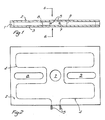
- the spacer assembly shown in Figures 1 and 2 comprises a rectangular layer 1 of aluminium, sandwiched between two similar, but thinner, rectangular layers 2 and 3 of polycarbonate.
- polycarbonate is a plastics material which is rigid and incompressible at machine shop temperatures but which will soften when heated to a temperature above 140°C.
- Embedded in the aluminium layer 1 is an electrical heating element 4 having terminals 5 projecting from one edge of the layer for the purpose of connecting the element 4 to a suitable electrical power supply.
- the element 4 is arranged to heat the layer 1 substantially evenly throughout and to a temperature sufficient for the polycarbonate layers 2 and 3 in contact with the aluminium layer 1 to soften whereby the thickness of the layers 2 and 3, and therefore the overall thickness of the spacer assembly, will decrease if the assembly is subjected to sufficient compression in a direction normal to the layers 1, 2 and 3 as indicated by the arrows 6.
- the layers 1, 2 and 3 of the assembly have a central hole 7 extending through the layers, and a pair of slot- like openings 8 and 9 arranged on opposite sides of the central hole 7 as shown in Figure 2 and also extending through the layers.
- the central hole 7 is provided to accommodate the shank or spigot of a tool in the case when the spacer assembly is located between the tool and the ram of a press, and the slot like openings 8 and 9 are provided to accommodate the bolts by which the tool is fixed to the ram.
- the size of any spacer assembly, and the presence and positioning of the holes 7, 8 and 9, particularly the bolt holes 8 and 9, will depend upon the size and arrangement of the press in which the spacer assembly is to be used and on where the assembly is to be fitted in the press.
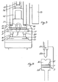
- a press fitted with a spacer assembly arranged as shown in Figures 1 and 2 is illustrated in Figure 3.
- the press comprises a press body 10 providing a horizontal press bed 11, and a ram 12 which is movable vertically towards and away from the press bed 11 in guides (not shown) on the press body 10.
- the ram 12 is reciprocated up and down by means of a driving mechanism (not shown) comprising a crank shaft which is driven by a motor through a clutch and a flywheel (part of which is shown at 13) and which is connected to the ram at 14 by a connecting rod having an adjusting screw 15 for fine adjustment of the press stroke.
- a press tool 16 comprising an upper die set 17 which is bolted to the ram 12 as shown at 18, a lower die set 19 which is bolted to the press bed 11, and telescopic guides 20 between the die sets 17 and 19.
- the spacer assembly formed by the layers 1, 2 and 3 is clamped between the upper die set 17 and the ram 12, as shown.
- the bolts 18 fixing the upper die set 17 to the ram pass through the openings 8 and 9 of the spacer assembly, and a spigot 21 which projects from the upper surface of the die set 17 into a socket in the ram 12 passes through the central opening 7 of the spacer assembly.
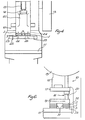
- the press shown in Figure 4 differs from that of Figure 3 in that its ram 22 has a detachable ram plate 23 bolted (as shown at 24) to the main part of the ram at its lower end, and in use the upper die set of a tool (not shown) is bolted to this ram plate 23 at positions 25.
- a spacer assembly 1, 2 and 3 is clamped between the ram plate 23 and the main part of the ram 22, and in effect becomes part of the ram, the assembly remaining permanently fixed in position until the plastics layers 2 and 3 need replacing following operation of the assembly to release a jam in the press.
- the spacer assembly used in the press of Figure 4 may be similar to that shown in Figures 1 and 2, although it may be unnecessary to provide the central opening 7 since the spigot of the tool will project into an opening 26 in the ram plate 23.
- the construction and operation of the press shown in Figure 4 is similar to that of the press shown in Figure 3.
- Figure 5 illustrates very diagrammatically a press-brake in which a horizontal press beam 27 is driven vertically; towards and away from a horizontal press bed 28.
- An elongated tool 29 is clamped to the press beam 27 and is arranged to co-operate during a press stroke with a V-block 30 bolted to the press bed 28 to produce an angle section from a metal plate or strip placed between them.
- a suitably sized elongated spacer assembly 1, 2 and 3 is clamped between the V-block 30 and the press bed 28.
- the press shown in Figure 6 is similar to that shown in Figure 3, and corresponding parts have been given the same reference numerals.
- a spacer assembly is not located between the tool 16 and the ram 12, but instead spacer assemblies in the form of parallels 31 are clamped between the lower die set 19 and the press bed 11.
- Each of the parallels 31 consists of an aluminium layer 1 (containing an electrical heating element) sandwiched between two polycarbonate layers 2 and 3 in much the same way as described with reference to Figures 1 and 2, but in addition there are two steel layers 32 and 33 which are face to face with the plastics layers 2 and 3 and which provide the parallel with outer protective faces.
- each parallel 31 are firmly connected together to form a unit, in contrast to the spacer assemblies used in the other examples described above, in which the layers 1, 2 and 3 are not firmly connected together except when clamped in position in a press.
Landscapes
- Engineering & Computer Science (AREA)
- Mechanical Engineering (AREA)
- Press Drives And Press Lines (AREA)
Claims (8)
Applications Claiming Priority (2)
| Application Number | Priority Date | Filing Date | Title |
|---|---|---|---|
| GB36978 | 1978-01-05 | ||
| GB36978 | 1978-01-05 |
Publications (2)
| Publication Number | Publication Date |
|---|---|
| EP0003076A1 EP0003076A1 (de) | 1979-07-25 |
| EP0003076B1 true EP0003076B1 (de) | 1981-02-11 |
Family
ID=9703201
Family Applications (1)
| Application Number | Title | Priority Date | Filing Date |
|---|---|---|---|
| EP78300835A Expired EP0003076B1 (de) | 1978-01-05 | 1978-12-15 | Presse mit einem Zwischenstück und Ausbildung des Zwischenstückes |
Country Status (3)
| Country | Link |
|---|---|
| US (1) | US4207048A (de) |
| EP (1) | EP0003076B1 (de) |
| DE (1) | DE2860496D1 (de) |
Families Citing this family (8)
| Publication number | Priority date | Publication date | Assignee | Title |
|---|---|---|---|---|
| US4624125A (en) * | 1985-02-11 | 1986-11-25 | Redicon Corporation | Method and apparatus for controlling the spacing between a metal forming punch and a complemental die |
| US4873859A (en) * | 1987-02-09 | 1989-10-17 | Redicon Corporation | Apparatus for controlling movement in a single action forming press |
| US4796454A (en) * | 1987-02-09 | 1989-01-10 | Redicon Corporation | Method for controlling movement in a single action forming press |
| US4800743A (en) * | 1987-07-28 | 1989-01-31 | Redicon Corporation | Method and apparatus for accommodating thermal expansion and other variances in presses |
| GB2340425A (en) * | 1998-08-13 | 2000-02-23 | Rover Group | Die support for a press tool |
| DE10161489C1 (de) * | 2001-12-14 | 2003-07-10 | Siempelkamp Gmbh & Co | Presse, insbesondere Ein- oder Mehretagenpresse, kontinuierliche Presse o. dgl., sowie Verfahren zum Herstellen von Presserahmen |
| DE102007012860B4 (de) * | 2007-03-17 | 2010-08-26 | Schuler Pressen Gmbh & Co. Kg | Werkzeug für eine Presse mit variabler Steifigkeit |
| ES2379715B1 (es) * | 2009-12-04 | 2013-07-09 | Fagor, S. Coop. | Cabezal para una maquina de estirado de chapas metalicas |
Family Cites Families (16)
| Publication number | Priority date | Publication date | Assignee | Title |
|---|---|---|---|---|
| US1847620A (en) * | 1930-09-29 | 1932-03-01 | Smith Corp A O | Press |
| US2478165A (en) * | 1946-05-24 | 1949-08-02 | Owens Corning Fiberglass Corp | Low-pressure molding apparatus |
| US2578209A (en) * | 1949-11-30 | 1951-12-11 | Art Electrotype Company | Method of making molds for electrotypes |
| US2907070A (en) * | 1955-03-25 | 1959-10-06 | Carroll H Van Hartesveldt | Temperature control apparatus for a mold |
| US3173190A (en) * | 1962-05-29 | 1965-03-16 | Pressure Castings Inc | Apparatus for placing and trimming packing inserts and the like |
| US3311692A (en) * | 1963-05-08 | 1967-03-28 | Union Carbide Corp | Gravure embossing of thermoplastics |
| DE1260928B (de) * | 1963-07-13 | 1968-02-08 | Smeralovy Zd Y Narodni Podnik | Vorrichtung zum Freisetzen eines festgeklemmten Stoessels einer vertikalen Schmiedepresse |
| US3475521A (en) * | 1966-03-04 | 1969-10-28 | John H Stroop | Method of making plastic contact lenses |
| GB1169192A (en) * | 1966-05-17 | 1969-10-29 | Samuel Griffiths Willenhall Lt | Improvements in or relating to Power Presses and like Machines |
| NL6715232A (de) * | 1966-06-04 | 1969-05-13 | ||
| DE6610318U (de) * | 1966-10-22 | 1973-09-27 | Berker Geb | Einrichtung zum loesen des festgefahrenen baeren von stanzen und dgl. |
| US3743463A (en) * | 1970-09-21 | 1973-07-03 | Union Carbide Corp | Mold construction having thermal baffle for molding articles without distortion such as plastic printing plates and the like |
| FR2209967B1 (de) * | 1972-12-08 | 1979-03-30 | Thomson Csf | |
| US3819315A (en) * | 1973-01-09 | 1974-06-25 | Ted Bildplatten | Apparatus for stamping information carriers from a plastic foil |
| NL7415442A (nl) * | 1974-11-27 | 1976-05-31 | Philips Nv | Persinrichting voor het vervaardigen van kunst- stofvoorwerpen, in het bijzonder grammofoon- en beeldplaten. |
| DE2531956A1 (de) * | 1975-07-17 | 1977-02-03 | Georg Bornatsch | Vorrichtung zum entspannen von verklemmten maschinen, insbesondere von festgefahrenen pressen, stanzen usw. |
-
1978
- 1978-12-15 EP EP78300835A patent/EP0003076B1/de not_active Expired
- 1978-12-15 DE DE7878300835T patent/DE2860496D1/de not_active Expired
- 1978-12-26 US US05/973,291 patent/US4207048A/en not_active Expired - Lifetime
Also Published As
| Publication number | Publication date |
|---|---|
| US4207048A (en) | 1980-06-10 |
| DE2860496D1 (en) | 1981-03-26 |
| EP0003076A1 (de) | 1979-07-25 |
Similar Documents
| Publication | Publication Date | Title |
|---|---|---|
| CN105856892B (zh) | 一种财务表单的打孔装订机及使用方法 | |
| US4207048A (en) | Power presses and components for such presses | |
| CN110640319A (zh) | 一种方形锂电池模组端侧板激光焊接装置 | |
| CN222965287U (zh) | 一种锂电池夹紧装置 | |
| CN220429281U (zh) | 一种led显示模块的薄膜二次贴合设备 | |
| CN211467829U (zh) | 一种模切烫金机加热用锁紧装置 | |
| CN221364977U (zh) | 汽车保险杠钻孔夹具 | |
| CN210224813U (zh) | 一种电缆热补器 | |
| CN219164402U (zh) | 直线电机铁芯自粘叠压工装 | |
| CN101791809B (zh) | 一种垫片加工设备 | |
| CN213134741U (zh) | 一种方便定位的钣金件快速冲压成型模具 | |
| CN211311303U (zh) | 一种用于玻璃热弯机的可调节压合机构 | |
| CN215921315U (zh) | 一种点火具冲盖垫片加工装置 | |
| CN209736459U (zh) | 一种带冲力监测的冲压模具 | |
| CN207723266U (zh) | 一种固定节叉的内花键用成型工装 | |
| CN217142965U (zh) | 一种用于控制器生产的预压装置 | |
| CN215090219U (zh) | 一种用于高强度板热压成形冲压模具 | |
| CN217343753U (zh) | 一种用于耐磨片铣削批量加工的夹具 | |
| CN217570256U (zh) | 一种校正装置 | |
| CN221209623U (zh) | 一种钣金压槽弯曲模具 | |
| CN210939488U (zh) | 一种活动刀模加热板 | |
| CN216575226U (zh) | 一种汽车滑轨解锁机构铆压接设备 | |
| CN216989548U (zh) | 成型铣切复合模具 | |
| CN223948512U (zh) | 一种扁管热压贴膜机工装夹具 | |
| CN214866456U (zh) | 一种高效率开式可倾式压力机 |
Legal Events
| Date | Code | Title | Description |
|---|---|---|---|
| PUAI | Public reference made under article 153(3) epc to a published international application that has entered the european phase |
Free format text: ORIGINAL CODE: 0009012 |
|
| AK | Designated contracting states |
Designated state(s): BE CH DE FR IT NL SE |
|
| 17P | Request for examination filed | ||
| ITF | It: translation for a ep patent filed | ||
| GRAA | (expected) grant |
Free format text: ORIGINAL CODE: 0009210 |
|
| AK | Designated contracting states |
Designated state(s): BE CH DE FR IT NL SE |
|
| REF | Corresponds to: |
Ref document number: 2860496 Country of ref document: DE Date of ref document: 19810326 |
|
| PGFP | Annual fee paid to national office [announced via postgrant information from national office to epo] |
Ref country code: SE Payment date: 19811130 Year of fee payment: 4 |
|
| PGFP | Annual fee paid to national office [announced via postgrant information from national office to epo] |
Ref country code: FR Payment date: 19811217 Year of fee payment: 4 |
|
| PGFP | Annual fee paid to national office [announced via postgrant information from national office to epo] |
Ref country code: NL Payment date: 19811231 Year of fee payment: 4 Ref country code: BE Payment date: 19811231 Year of fee payment: 4 |
|
| PG25 | Lapsed in a contracting state [announced via postgrant information from national office to epo] |
Ref country code: BE Effective date: 19821215 |
|
| PG25 | Lapsed in a contracting state [announced via postgrant information from national office to epo] |
Ref country code: SE Effective date: 19821216 |
|
| PG25 | Lapsed in a contracting state [announced via postgrant information from national office to epo] |
Ref country code: CH Effective date: 19821231 |
|
| PG25 | Lapsed in a contracting state [announced via postgrant information from national office to epo] |
Ref country code: NL Effective date: 19830701 |
|
| NLV4 | Nl: lapsed or anulled due to non-payment of the annual fee | ||
| PG25 | Lapsed in a contracting state [announced via postgrant information from national office to epo] |
Ref country code: FR Free format text: LAPSE BECAUSE OF NON-PAYMENT OF DUE FEES Effective date: 19830831 |
|
| REG | Reference to a national code |
Ref country code: CH Ref legal event code: PL |
|
| PG25 | Lapsed in a contracting state [announced via postgrant information from national office to epo] |
Ref country code: DE Effective date: 19830901 |
|
| REG | Reference to a national code |
Ref country code: FR Ref legal event code: ST |
|
| EUG | Se: european patent has lapsed |
Ref document number: 78300835.2 Effective date: 19850611 |
|
| PLBE | No opposition filed within time limit |
Free format text: ORIGINAL CODE: 0009261 |
|
| STAA | Information on the status of an ep patent application or granted ep patent |
Free format text: STATUS: NO OPPOSITION FILED WITHIN TIME LIMIT |