EP0003252A1 - Procédé pour la réalisation de fermetures à curseur munies de spires de verrouillage - Google Patents
Procédé pour la réalisation de fermetures à curseur munies de spires de verrouillage Download PDFInfo
- Publication number
- EP0003252A1 EP0003252A1 EP78300752A EP78300752A EP0003252A1 EP 0003252 A1 EP0003252 A1 EP 0003252A1 EP 78300752 A EP78300752 A EP 78300752A EP 78300752 A EP78300752 A EP 78300752A EP 0003252 A1 EP0003252 A1 EP 0003252A1
- Authority
- EP
- European Patent Office
- Prior art keywords
- chain
- dye
- slide fasteners
- thickener
- fastener
- Prior art date
- Legal status (The legal status is an assumption and is not a legal conclusion. Google has not performed a legal analysis and makes no representation as to the accuracy of the status listed.)
- Granted
Links
- 238000004519 manufacturing process Methods 0.000 title claims abstract description 23
- 238000000034 method Methods 0.000 title description 25
- 229920001187 thermosetting polymer Polymers 0.000 claims abstract description 12
- 239000006185 dispersion Substances 0.000 claims abstract description 8
- 238000003490 calendering Methods 0.000 claims abstract description 6
- 238000004043 dyeing Methods 0.000 claims description 20
- 239000002562 thickening agent Substances 0.000 claims description 18
- 238000005406 washing Methods 0.000 claims description 16
- 229920000728 polyester Polymers 0.000 claims description 14
- 239000004744 fabric Substances 0.000 claims description 13
- 238000001035 drying Methods 0.000 claims description 7
- 239000000463 material Substances 0.000 claims description 7
- 238000011282 treatment Methods 0.000 claims description 7
- 239000007788 liquid Substances 0.000 claims description 6
- 238000007654 immersion Methods 0.000 claims description 5
- 239000003945 anionic surfactant Substances 0.000 claims description 4
- 230000037303 wrinkles Effects 0.000 claims description 4
- 230000000694 effects Effects 0.000 claims description 3
- 229920002134 Carboxymethyl cellulose Polymers 0.000 claims description 2
- 239000007790 solid phase Substances 0.000 claims 2
- 239000001768 carboxy methyl cellulose Substances 0.000 claims 1
- 235000010948 carboxy methyl cellulose Nutrition 0.000 claims 1
- 239000008112 carboxymethyl-cellulose Substances 0.000 claims 1
- 239000012530 fluid Substances 0.000 claims 1
- 238000010438 heat treatment Methods 0.000 abstract description 10
- 238000011437 continuous method Methods 0.000 abstract description 2
- 238000003825 pressing Methods 0.000 abstract description 2
- 229920005989 resin Polymers 0.000 abstract description 2
- 239000011347 resin Substances 0.000 abstract description 2
- 238000009958 sewing Methods 0.000 abstract description 2
- 230000008021 deposition Effects 0.000 abstract 1
- 239000000975 dye Substances 0.000 description 35
- 239000000243 solution Substances 0.000 description 9
- 238000012545 processing Methods 0.000 description 8
- 238000010409 ironing Methods 0.000 description 5
- 238000009991 scouring Methods 0.000 description 5
- 239000003795 chemical substances by application Substances 0.000 description 4
- 230000003472 neutralizing effect Effects 0.000 description 4
- 239000004033 plastic Substances 0.000 description 4
- HEMHJVSKTPXQMS-UHFFFAOYSA-M Sodium hydroxide Chemical compound [OH-].[Na+] HEMHJVSKTPXQMS-UHFFFAOYSA-M 0.000 description 3
- 238000012544 monitoring process Methods 0.000 description 3
- 229920001225 polyester resin Polymers 0.000 description 3
- 239000004645 polyester resin Substances 0.000 description 3
- 238000012546 transfer Methods 0.000 description 3
- 239000007864 aqueous solution Substances 0.000 description 2
- 230000007812 deficiency Effects 0.000 description 2
- 230000002950 deficient Effects 0.000 description 2
- 230000002939 deleterious effect Effects 0.000 description 2
- 238000009975 hank dyeing Methods 0.000 description 2
- 230000001788 irregular Effects 0.000 description 2
- 239000002699 waste material Substances 0.000 description 2
- XLYOFNOQVPJJNP-UHFFFAOYSA-N water Substances O XLYOFNOQVPJJNP-UHFFFAOYSA-N 0.000 description 2
- QMGYPNKICQJHLN-UHFFFAOYSA-M Carboxymethylcellulose cellulose carboxymethyl ether Chemical compound [Na+].CC([O-])=O.OCC(O)C(O)C(O)C(O)C=O QMGYPNKICQJHLN-UHFFFAOYSA-M 0.000 description 1
- 206010037867 Rash macular Diseases 0.000 description 1
- 239000002253 acid Substances 0.000 description 1
- 230000002411 adverse Effects 0.000 description 1
- WYTGDNHDOZPMIW-RCBQFDQVSA-N alstonine Natural products C1=CC2=C3C=CC=CC3=NC2=C2N1C[C@H]1[C@H](C)OC=C(C(=O)OC)[C@H]1C2 WYTGDNHDOZPMIW-RCBQFDQVSA-N 0.000 description 1
- 230000004075 alteration Effects 0.000 description 1
- 230000015572 biosynthetic process Effects 0.000 description 1
- 238000006243 chemical reaction Methods 0.000 description 1
- 238000004140 cleaning Methods 0.000 description 1
- 238000004040 coloring Methods 0.000 description 1
- 238000010014 continuous dyeing Methods 0.000 description 1
- 238000010924 continuous production Methods 0.000 description 1
- 238000004132 cross linking Methods 0.000 description 1
- 238000005520 cutting process Methods 0.000 description 1
- 230000007547 defect Effects 0.000 description 1
- 239000000986 disperse dye Substances 0.000 description 1
- 238000009826 distribution Methods 0.000 description 1
- 238000010981 drying operation Methods 0.000 description 1
- 238000005485 electric heating Methods 0.000 description 1
- 239000000835 fiber Substances 0.000 description 1
- 150000002500 ions Chemical class 0.000 description 1
- 238000009940 knitting Methods 0.000 description 1
- 239000000314 lubricant Substances 0.000 description 1
- 238000002844 melting Methods 0.000 description 1
- 230000008018 melting Effects 0.000 description 1
- 239000000203 mixture Substances 0.000 description 1
- 238000012986 modification Methods 0.000 description 1
- 230000004048 modification Effects 0.000 description 1
- 238000009974 package dyeing Methods 0.000 description 1
- 230000000704 physical effect Effects 0.000 description 1
- 230000003252 repetitive effect Effects 0.000 description 1
- 150000003839 salts Chemical class 0.000 description 1
- 230000037339 smooth wrinkles Effects 0.000 description 1
- JVBXVOWTABLYPX-UHFFFAOYSA-L sodium dithionite Chemical compound [Na+].[Na+].[O-]S(=O)S([O-])=O JVBXVOWTABLYPX-UHFFFAOYSA-L 0.000 description 1
- 235000011121 sodium hydroxide Nutrition 0.000 description 1
- 238000000859 sublimation Methods 0.000 description 1
- 230000008022 sublimation Effects 0.000 description 1
- 239000000126 substance Substances 0.000 description 1
- 239000004753 textile Substances 0.000 description 1
- 238000005382 thermal cycling Methods 0.000 description 1
- 230000003313 weakening effect Effects 0.000 description 1
- 238000004804 winding Methods 0.000 description 1
Images


Classifications
-
- B—PERFORMING OPERATIONS; TRANSPORTING
- B29—WORKING OF PLASTICS; WORKING OF SUBSTANCES IN A PLASTIC STATE IN GENERAL
- B29D—PRODUCING PARTICULAR ARTICLES FROM PLASTICS OR FROM SUBSTANCES IN A PLASTIC STATE
- B29D5/00—Producing elements of slide fasteners; Combined making and attaching of elements of slide fasteners
-
- A—HUMAN NECESSITIES
- A44—HABERDASHERY; JEWELLERY
- A44B—BUTTONS, PINS, BUCKLES, SLIDE FASTENERS, OR THE LIKE
- A44B19/00—Slide fasteners
- A44B19/42—Making by processes not fully provided for in one other class, e.g. B21D53/50, B21F45/18, B22D17/16, B29D5/00
-
- Y—GENERAL TAGGING OF NEW TECHNOLOGICAL DEVELOPMENTS; GENERAL TAGGING OF CROSS-SECTIONAL TECHNOLOGIES SPANNING OVER SEVERAL SECTIONS OF THE IPC; TECHNICAL SUBJECTS COVERED BY FORMER USPC CROSS-REFERENCE ART COLLECTIONS [XRACs] AND DIGESTS
- Y10—TECHNICAL SUBJECTS COVERED BY FORMER USPC
- Y10S—TECHNICAL SUBJECTS COVERED BY FORMER USPC CROSS-REFERENCE ART COLLECTIONS [XRACs] AND DIGESTS
- Y10S264/00—Plastic and nonmetallic article shaping or treating: processes
- Y10S264/40—Processes of coiling plastics
-
- Y—GENERAL TAGGING OF NEW TECHNOLOGICAL DEVELOPMENTS; GENERAL TAGGING OF CROSS-SECTIONAL TECHNOLOGIES SPANNING OVER SEVERAL SECTIONS OF THE IPC; TECHNICAL SUBJECTS COVERED BY FORMER USPC CROSS-REFERENCE ART COLLECTIONS [XRACs] AND DIGESTS
- Y10—TECHNICAL SUBJECTS COVERED BY FORMER USPC
- Y10S—TECHNICAL SUBJECTS COVERED BY FORMER USPC CROSS-REFERENCE ART COLLECTIONS [XRACs] AND DIGESTS
- Y10S8/00—Bleaching and dyeing; fluid treatment and chemical modification of textiles and fibers
- Y10S8/92—Synthetic fiber dyeing
- Y10S8/922—Polyester fiber
-
- Y—GENERAL TAGGING OF NEW TECHNOLOGICAL DEVELOPMENTS; GENERAL TAGGING OF CROSS-SECTIONAL TECHNOLOGIES SPANNING OVER SEVERAL SECTIONS OF THE IPC; TECHNICAL SUBJECTS COVERED BY FORMER USPC CROSS-REFERENCE ART COLLECTIONS [XRACs] AND DIGESTS
- Y10—TECHNICAL SUBJECTS COVERED BY FORMER USPC
- Y10T—TECHNICAL SUBJECTS COVERED BY FORMER US CLASSIFICATION
- Y10T24/00—Buckles, buttons, clasps, etc.
- Y10T24/25—Zipper or required component thereof
- Y10T24/2518—Zipper or required component thereof having coiled or bent continuous wire interlocking surface
- Y10T24/2527—Attached by stitching
- Y10T24/2529—String or stringer tape having distinctive property [e.g., heat sensitive]
Definitions
- This invention relates to a continuous method of manufacturing a coil type slide fastener chain which when cut to length and provided with sliders and stops produces modern type zippers.
- Coil type slide fasteners have heretofore been manufactured by initially hot forming or thermosetting synthetic plastic monofilaments to their coil or helical configuration. These heat treated coils may then be coupled together and affixed to the edges of fabric tapes, providing a continuous length slide fastener chain which is collected by loosely coiling for further processing. Invariably, dyeing of the fastener chain is accomplished by batch processing, known as package or skein dyeing. Unfortunately, these prior processes frequently result in fasteners which have a relatively high failure rate and the coils have a tendency to pop open when folded or stressed. It has been found that one of the major factors contributing to this tendency is the excessive brittleness of the monofilament coils which results from multiple exposure of the coils to excessively high processing temperatures.
- the filaments are subjected to elevated temperature during the coiling state, such as when the monofilament is wound around a heated mandrel or on a mandrel disposed in heated zone.
- High temperature on the order of 180-200° F have been used to insure that the coil will remain in its helical configuration so that the pairs of coils can be interlocked and sewn onto the fabric tapes.
- the coil and tapes are again subjected to high temperatures during final thermofixing of the coil and again during batch dyeing, scouring and calendering.
- the thermosetting resin which forms the coil. It will be realized that such heat treatment causes changes in the molecular structure of the material and thus tends to make it excessively rigid or brittle and also adversely affects its receptivity to dyestuffs.
- the process comprises the steps of forming a pair of fastener coils from a monofilament of heat settable synthetic plastic such as polyester.
- the coils is formed at a mild or moderate temperature.
- the coils are thereafter coupled together and sewn onto fabric tapes composed of the same synthetic plastic as the coil.
- the fastener chain which consists of the coil and fabric tapes is maintained at a selected tension and advanced at a given velocity throughout the remainder of the process wherein the fabrication of the chain, including its dyeing and thermosetting, is accomplished without interruption. If for any reason the shade or color of the continuously moving chain is unsuitable, its velocity through previous processing steps can be modified to obtain optimum product quality.
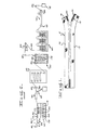
- a sliding clasp fastener chain 5 manufactured in accordance with the present invention and comprising a pair of fabric tapes 10, each having a helical coil element 15 secured along the edge the reof as by sewing.
- the tapes may be a woven or knitted fabric of thermosetting synthetic plastic fibers, such as a polyester.
- Each coil is formed from a continuous length of heat settable monofilament material, preferably a polyester resin, the same as the tape.
- the polyester monofilament is wound about a suitable mandrel and shaped to provide a multiplicity of longitudinally spaced interlocking coils 20, such as shown in United States Patent No. 3, 199, 162 to Sohr et al.
- the fastener coil or helix ... is formed by winding a synthetic monofilament about a mandrel in the manner such as disclosed in the aforementioned patent to Sohr et al.
- the coil is heated by a suitable heating source to a temperature in the range of 135° to 145° F. This is a relatively mild or moderate temperature which facilitates formation of the coil and imparts sufficient form stability to the monofilament coil but without deleterious thermal effect on the polyester resin of which the coil is formed.
- a pair of monofilament coils are then coupled together and sewn onto the adjacent edges of a pair of fabric tapes to form a fastener chain which is constituted of the tapes and pair of intermeshed coils, as shown in Fig. 1.
- this continuous chain will be cut to length and provided with end stops and sliders to form large numbers of slide fasteners.
- the remainder of the processing steps embodying this invention including dyeing, thermofixing, washing and calendering are carried out as a continuous uninterrupted process in which the fastener chain is kept under controlled tension throughout the fabricating processes whereby uncoiling of the helix and wrinkling of the fabric tapes is avoided.
- the chain is processed, as schematically illustrated in Fig. 2.
- the chain is advanced under contrdled tension and velocity through the various treatment stations by any suitable means, such as an electric drive motor (not shown).
- the fastener chain is first led through an ironing or pressing apparatus as illustrated at 25 for removal of wrinkles or creases and thereafter through a liquid dye bath 30 and then through a dye leveler 35 which uniformly distributes the dye over the coil and tapes.
- a vacuum device 40 then removes excess dye and recirculates it back to the dye bath vat.
- the chain is dried in dryer 45 and drawn through a heating chamber 50 maintained at a temperature in the range of 390° to 400° F, which is the curing or setting temperature of the polyester coil and fabric and the fixing temperature of the dyestuffs.
- the chain is then drawn over a central balance tensioning device 55 which maintains the chain uniformly tensioned throughout the process embodying this invention.
- the chain is then advanced through a scouring and rinsing apparatus 60 wherein the chain is cleaned, rinsed and treated with a finishing agent.
- Calendering by rollers 65 and drying in tube 70 completes the processing.
- Calender rollers 65 and dryer 70 cooperate to smooth and dry the chain while contrdling the tension thereof.
- the chain is collected at 75 for final cutting and assembly with suitable end stops and a slider mechanism.
- various rollers 80 are employed to direct the chain to the apparatus noted hereinabove and may at the same time be employed to connect the chain to the drive means and control the tension within the chain. Such rollers are well known in the field of textile web
- ironing device 25 presses the tapes 10 before the dyeing thereof, thereby preventing irregularities in color shading due to collection of excess dye in any wrinkles or creases existing in the tape.
- Ironing device 25 comprises a housing 82 enclosing upper and lower heat transfer plates 85 and 90, respectively.
- the heat transfer plates are electrically heated by thermostatically controlled electric heating elements.
- the heating element for upper plate 85 is shown at 95 and the thermostatic control therefor is shown at 100.
- a similar heating element and thermostatic control (not shown) are provided for lower plate 90.
- the lower plate is maintained at a temperature of approximately 180° F, while the upper plate, due to its spacing from the chain, may be maintained at a higher temperature of 320° F. Temperature in the range of 160° to 250° F has been found effective to remove wrinkles from the tapes without thermosetting or curing of the tape or coil owing to the continuous rate of movement of the chain through the ironing device.
- the chain is next advanced through dye bath 30 comprising a dye vat 110 containing a reservoir of suitable dye 115 (see Fig. 2).
- the continuous dyeing operation allows constant monitoring of the chain color and if necessary immediate adjustment of the operating parameters, such as chain speed through the dye bath and/or dye composition. Such immediate and continuous control is not possible in prior art batch or skein dyeing processes wherein such monitoring of the dyeing process is impnssible.
- the dye is preferably maintained at room temperature to avoid any deleterious thermal effects on the chain.
- the dye used consists essentially of a combination of a dispersion dyestuff, thickener, and an anionic surfactant.
- the aqueous dye bath consists by weight of about 85% to 90% of a dispersion of dyestuffs, 10% to 15% carboxymethyl cellulose (CMC) thickener and 0. 1% of a suitable anionic surfactant, such as Permalene A-120.
- CMC carboxymethyl cellulose
- a suitable anionic surfactant such as Permalene A-120.
- the dye bath used in carrying out this invention is composed of an unusually large percentage of thickener, i. e., 10% to 15% as compared to conventional disperse dyes which contain only 1. 5% to 3% thickener.
- the dye is made up from high energy dyestuffs and a. premixed concentrated solution of 72 grams of dry CMC powder dispersed in each quart of water.
- the thickener is allowed to hydrate to form a smooth gel, and when mixed with the dye, relatively large quantities of dyestuffs are absorbed in the thickener whereby the dyestuffs are carried onto the fastener chain and particularly the monofilament coil as a uniform film or layer.
- the chain 5 makes four passes through the dye bath being led over tension rollers 120.
- the dye is agitated by a stirrer 125 powered by suitable drive means such as electric motor 130.
- the tapes 10 are preferably, knit from unset polyester yard, they are often contaminated with an oil used as a lubricant in the knitting of the yarn. Usually, it is necessary to cleanse the tapes to remove such oil residues prior to dyeing, otherwise the color shade and hue are not uniform and true. In the method of the present invention, however, uniformity of color and shaft are achieved without such a preliminary cleaning step. It is believed that in the present method, the anionic surfactant used in the dyeing solution causes the oil to be washed from the tapes, thereby providing a clean surface for adhesion of the dyestuffs. It is further believed that any oil remaining on the tapes after the dyeing thereof is either removed by the subsequent mechanical dye leveling or vaporized during the thermofixing step of the process.
- the chain is led through the dye leveler 35 comprising one or more pairs of opposed upper and lower brush pads 140 and 145 (Figs. 4 and 5) which uniformly distribute the dye over the irregular surfaces of the knit tapes and coil elements and into the interstices of these elements.
- Excess dye is then removed from the chain by passing the tensioned chain over vacuum device 40 including a suction head 150 which terminates at an orifice or port 151 over which the tape is drawn. Any excess dye so removed is returned by conduit 155 to dye vat 110 for reuse. Because of the relatively viscous nature of the dispersion dye, a uniform film or layer of thickener containing dyestuffs is applied to the fastener chain including the monofilament coil.
- dryer 45 comprises an insulated housing 160 having opposed vertical rows of spaced rollers 165 mounted therein and a heating element 170 disposed adjacent the bottom thereof.
- the chain enters the dryer at the upper portion thereof, winds about rollers 165 in serpentine fashion toward the lower end and exists near the bottom thereof.
- This multipass dryer allows the chain to be thoroughly dried without exposure to very high temperatures which when repeated in the subsequent thermofixing operation would likely cause the chain to become brittle.
- the gradual drying of the chain avoids hot spots which during the subsequent thermofixing operation, could result in dyeing problems, such as irregular coloring and also shrinkage , and weakening of the chain.
- the chain is led through a heater 50, wherein the chain material is thermoset and the dye simultaneously thermo- fixed.
- the polyester resin components undergo controlled crosslinking reactions which cause the tapes and stringers to stabilize in shape while simultaneously the dye sublimates or vaporizes from the thickener and migrates into the expanding molecular structure of the polyester to provide a colorfast zipper chain.
- Such sublimation dyeing is known as "thermosoling".
- the temperature within heater 50 is maintained in the range of 380° F to 420° F by a bath 175 of liquid having a melting point slightly higher than the thermosetting and thermofixing temperatures.
- the chain is received within a chamber or tubular conduit 80 in heat transfer relation to the bath, thereby preventing the direct contact of the chain with the bath solution. Since exposure to the thermosetting temperature within chamber 80 is the one and only time the chain is exposed to such elevated temperatures, the dye molecules will sublimate or vaporize from the thickener layer and penetrate the polyester molecule, ensuring permanent dyeing to a uniform color and shade throughout the chain components. Moreover, since the chain was not subjected to a number of wide temperature variations, the coil is found to have optimum physical properties both from the standpoint of appearance and functionality.
- apparatus 60 comprises a serial arrangement of separate chambers 185, 190 and 195.
- the bath chambers or units are substantially identical, each includes a tank 200, 210 and 215, having a lower guide roller 220 disposed adjacent the bottom thereof.
- An upper guide roller 225 is disposed parallel to each lower roller, above the corresponding tank.
- the rollers 225 may be mounted on a common shaft 227 driven by any suitable means, not shown: As shown in F ig.
- the slide fastener chain is looped in edge-to-edge relation around each pair of guide rollers in a helical fashion.
- the guide rollers serve to conform the chain into a plurality of adjacent loops, each partially immersed in the bath for sequential washing of the chain.
- An elongate vacuum manifold 230, provided with a longitudinal distribution of spaced ports 232 is disposed parallel to and between each pair of upper and lower guide rollers above the corresponding tank and serves to remove excess bath solution from the chain after each passage of the chain in the bath solution.
- First and second obliquely disposed rollers 235 and 240 guide the chain from tank 200 to tank 210 and from tank 210 to tank 215, respectively.
- the orientation of the tanks and rollers set forth hereinabove allows the chain to be repetitively immersed and treated in a tank of minimum liquid value, thereby conserving the treatment solution employed. Moreover, the repetitive immersion of the chain within each of the tanks is achieved on a single driven shaft 227 and a single vacuum conduit 230, whereby the several vacuum heads are connected to one vacuum source.
- this edge-to-edge type orientation enables the use in compact units of relatively generous diameter guide rolls 220 and 225 so that the chain is not tightly or sharply bent during the washing phase.
- Tank 200 contains a bath of a washing or scouring solution.
- the chain is washed in an aqueous solution of approx- imagely 50 grams per gallon of 50% liquid caustic soda and approximately 40 grams per gallon of sodium hydrosulfite maintained by suitable heaters (not shown) at a temperature of approximately 100-120° F.
- suitable heaters not shown
- the chain is drawn over the vacuum manifold which removes much of the contaminated washing solution from the chain.
- the neutralizing rinse comprises an aqueous solution of an acid salt, such as that marketed by Surpass Chemical Company under the mark "Sour XS".
- the chnin is drawn over the vacuum manifold which removes much of the contaminated neutralizing solution from the chain.
- the chain is led into tank 215 where it is rinsed in either a pure water rinse or if required, a finishing agent for modification of the hand of the fastener.
- the vacuum manifold in tank 215 removes much of the final rinsing agent from the chain subsequent to each pass through the bath.
- Dryer 250 comprises a tube housing 255 and a blow dryer 260 which injects heated air into the housing along the longitudinal axis of said chain.
- the air blown into the tube is heated to about 300° F, such as by electrical heating elements, which provides the finishing step for the tensioned chain.
- the close proximity of the calendering and drying apparatus at controlled tension results in a chain of smooth wrinkle free appearance.
- the continuous chain may be cut to predetermined lengths and assembled with end stops and sliders to complete the zipper manufacture.
- the process of the present invention overcomes many of the deficiencies of prior art slide fastener manufacturing processes.
- the continuous nature of the process minimizes large temperature variations or cycles inherent in prior batch type processes and enables monitoring of the appearance, hand and functionality of the polyester chain at each stage of its fabrication thereby providing for continuous control and adjustment of chain velocity and processing parameters in the various treatment apparatus. For example, uniformity of shade and color intensity is ensured by. controlling the dwell time of the polyester chain in the dye bath and/or in the thermofixing unit.
- thermosetting of the chain and thermofixing of the dye takes place immediately after the dyed chain is hot air dried in a heating chamber, the chain will remain at an elevated temperature when entering the thermofixing unit and thus not be subject to the wide temperature flu.cuations of the prior art.
- This process thus ensures color fast dyeing with uniformity of shade between the web and stringers and minimizes the incidence of defects in the mechanical properties of the coil caused by thermal cycling of the polyester material.
- a corrective measure can be promptly taken with minimum waste in terms of defective product. This was not feasible with previous manufacturing processes which involved batch treatment of the fastener chain.
Landscapes
- Engineering & Computer Science (AREA)
- Mechanical Engineering (AREA)
- Treatment Of Fiber Materials (AREA)
- Slide Fasteners (AREA)
Applications Claiming Priority (2)
| Application Number | Priority Date | Filing Date | Title |
|---|---|---|---|
| US05/858,071 US4162892A (en) | 1977-12-06 | 1977-12-06 | Method of manufacturing continuous coil slide fasteners |
| US858071 | 1997-05-16 |
Publications (2)
| Publication Number | Publication Date |
|---|---|
| EP0003252A1 true EP0003252A1 (fr) | 1979-08-08 |
| EP0003252B1 EP0003252B1 (fr) | 1983-08-24 |
Family
ID=25327411
Family Applications (1)
| Application Number | Title | Priority Date | Filing Date |
|---|---|---|---|
| EP78300752A Expired EP0003252B1 (fr) | 1977-12-06 | 1978-12-06 | Procédé pour la réalisation de fermetures à curseur munies de spires de verrouillage |
Country Status (5)
| Country | Link |
|---|---|
| US (1) | US4162892A (fr) |
| EP (1) | EP0003252B1 (fr) |
| JP (1) | JPS5492439A (fr) |
| CA (1) | CA1112409A (fr) |
| DE (1) | DE2862308D1 (fr) |
Cited By (2)
| Publication number | Priority date | Publication date | Assignee | Title |
|---|---|---|---|---|
| EP0632974A1 (fr) * | 1993-07-09 | 1995-01-11 | Ykk Corporation | Fermeture à glissière en résine synthétique |
| CN113047047A (zh) * | 2019-12-27 | 2021-06-29 | Ykk株式会社 | 拉链牙链带的制造方法、拉链链条 |
Families Citing this family (8)
| Publication number | Priority date | Publication date | Assignee | Title |
|---|---|---|---|---|
| US4531947A (en) * | 1982-01-08 | 1985-07-30 | R. Englehardt Nominees Pty. Ltd. | Color process for spectacle frame coated with polyester |
| AU3678995A (en) * | 1994-09-20 | 1996-04-09 | Willard H. Strom | Temporary shelter and method of making same |
| JPH10243805A (ja) * | 1997-03-05 | 1998-09-14 | Ykk Corp | 合成樹脂製スライドファスナー |
| JPH1170005A (ja) * | 1997-08-29 | 1999-03-16 | Ykk Corp | スライドファスナー用チェン |
| GB2332020A (en) * | 1997-12-03 | 1999-06-09 | Ykk Europ Ltd | Cleaning zip fastener |
| KR20030076758A (ko) * | 2002-03-21 | 2003-09-29 | 김영재 | 규격별로 직조된 점착용 매직테이프의 원단을 슬릿팅하는슬릿팅장치와 슬릿팅장치에 의하여 생산되는 규격 점착용매직테이프의 제조방법 |
| US20080000064A1 (en) * | 2006-06-28 | 2008-01-03 | Ching Song Chou | Method of Manufacturing Color Metal Zipper and Apparatus Therefor |
| CN109312533B (zh) * | 2016-06-10 | 2021-01-15 | Ykk株式会社 | 拉链用带状构件的染色方法和染色装置 |
Citations (7)
| Publication number | Priority date | Publication date | Assignee | Title |
|---|---|---|---|---|
| DE741679C (de) * | 1939-07-05 | 1943-11-15 | Ig Farbenindustrie Ag | Reissverschluss |
| US3199162A (en) * | 1962-09-07 | 1965-08-10 | Sohr Hans-Uhich | Continuous slide fastener |
| DE1213656B (de) * | 1962-06-01 | 1966-03-31 | Sohr Hans Ulrich | Verfahren zum Herstellen eines Reissverschlusses |
| US3354853A (en) * | 1963-09-06 | 1967-11-28 | Sohr Hans Ulrich | Process of manufacturing sliding clasp fasteners |
| DE1808358A1 (de) * | 1967-11-21 | 1969-06-04 | Sohr Hans Ulrich | Reissverschluss und Verfahren zu seiner Herstellung |
| US3768967A (en) * | 1972-04-05 | 1973-10-30 | Sohr Hans Ulrich | Device for heat treatment of strips and the like |
| DE2706167A1 (de) * | 1976-02-19 | 1977-08-25 | Textron Inc | Mit einem polymer ueberzogene einfaerbbare gegenstaende sowie verfahren zur herstellung solcher gegenstaende |
Family Cites Families (7)
| Publication number | Priority date | Publication date | Assignee | Title |
|---|---|---|---|---|
| US2334000A (en) * | 1939-12-13 | 1943-11-09 | Talon Inc | Color treatment of slide fasteners |
| US3137036A (en) * | 1961-07-17 | 1964-06-16 | Conmar Prod Corp | Method and apparatus for making plastic slide fasteners |
| US3170014A (en) * | 1962-02-07 | 1965-02-16 | Scovill Manufacturing Co | Coil forming method and apparatus for zipper fasteners |
| GB1133846A (en) * | 1965-04-28 | 1968-11-20 | Opti Holding Ag | Improvements in or relating to the production of sliding clasp fastener interlocking elements from thermoplastic filaments |
| US3908242A (en) * | 1973-05-10 | 1975-09-30 | Textron Inc | Continuous filament slide fastener |
| GB1464064A (en) * | 1974-07-15 | 1977-02-09 | Teijin Ltd | Interlocking fastening elements for zip fasteners made of polyester monofilaments |
| US3939547A (en) * | 1974-08-28 | 1976-02-24 | Textron, Inc. | Method of producing a dyeable coating on metal article |
-
1977
- 1977-12-06 US US05/858,071 patent/US4162892A/en not_active Expired - Lifetime
-
1978
- 1978-12-04 CA CA317,307A patent/CA1112409A/fr not_active Expired
- 1978-12-06 EP EP78300752A patent/EP0003252B1/fr not_active Expired
- 1978-12-06 JP JP15093478A patent/JPS5492439A/ja active Pending
- 1978-12-06 DE DE7878300752T patent/DE2862308D1/de not_active Expired
Patent Citations (7)
| Publication number | Priority date | Publication date | Assignee | Title |
|---|---|---|---|---|
| DE741679C (de) * | 1939-07-05 | 1943-11-15 | Ig Farbenindustrie Ag | Reissverschluss |
| DE1213656B (de) * | 1962-06-01 | 1966-03-31 | Sohr Hans Ulrich | Verfahren zum Herstellen eines Reissverschlusses |
| US3199162A (en) * | 1962-09-07 | 1965-08-10 | Sohr Hans-Uhich | Continuous slide fastener |
| US3354853A (en) * | 1963-09-06 | 1967-11-28 | Sohr Hans Ulrich | Process of manufacturing sliding clasp fasteners |
| DE1808358A1 (de) * | 1967-11-21 | 1969-06-04 | Sohr Hans Ulrich | Reissverschluss und Verfahren zu seiner Herstellung |
| US3768967A (en) * | 1972-04-05 | 1973-10-30 | Sohr Hans Ulrich | Device for heat treatment of strips and the like |
| DE2706167A1 (de) * | 1976-02-19 | 1977-08-25 | Textron Inc | Mit einem polymer ueberzogene einfaerbbare gegenstaende sowie verfahren zur herstellung solcher gegenstaende |
Cited By (7)
| Publication number | Priority date | Publication date | Assignee | Title |
|---|---|---|---|---|
| EP0632974A1 (fr) * | 1993-07-09 | 1995-01-11 | Ykk Corporation | Fermeture à glissière en résine synthétique |
| US5500276A (en) * | 1993-07-09 | 1996-03-19 | Yoshida Kogyo K.K. | Slide fastener made of synthetic resin |
| CN113047047A (zh) * | 2019-12-27 | 2021-06-29 | Ykk株式会社 | 拉链牙链带的制造方法、拉链链条 |
| EP3842589A3 (fr) * | 2019-12-27 | 2021-12-22 | YKK Corporation | Procédé de fabrication d'une fermeture à glissière et fermeture à glissière |
| US11744332B2 (en) | 2019-12-27 | 2023-09-05 | Ykk Corporation | Fastener chain |
| CN113047047B (zh) * | 2019-12-27 | 2024-01-02 | Ykk株式会社 | 拉链牙链带的制造方法、拉链链条 |
| US12133579B2 (en) | 2019-12-27 | 2024-11-05 | Ykk Corporation | Method for manufacturing fastener stringer |
Also Published As
| Publication number | Publication date |
|---|---|
| JPS5492439A (en) | 1979-07-21 |
| DE2862308D1 (en) | 1983-09-29 |
| US4162892A (en) | 1979-07-31 |
| EP0003252B1 (fr) | 1983-08-24 |
| CA1112409A (fr) | 1981-11-17 |
Similar Documents
| Publication | Publication Date | Title |
|---|---|---|
| CN101289777B (zh) | 一种混彩牛仔布的生产工艺及其制成的混彩牛仔布 | |
| US4162892A (en) | Method of manufacturing continuous coil slide fasteners | |
| US3776004A (en) | Apparatus for the continuous treatment of thick, voluminous textile materials | |
| KR101580673B1 (ko) | 스판원단 주름방지 장치 | |
| US3619103A (en) | Process for producing heat-induced effects on textile fibers and fabrics | |
| US3943734A (en) | Apparatus for the continuous treatment of textile material | |
| US6497936B1 (en) | Method and apparatus for dyeing and treating yarns | |
| DE1660484A1 (de) | Verfahren zum gleichfoermigen Orientieren von synthetischen Faeden in Form von Kabeln oder Tauen mit grossem Titer | |
| CN111334952A (zh) | 一体式纱线染色设备 | |
| US4416124A (en) | Sheet-dyeing apparatus | |
| GB758442A (en) | Improvements in cellulose acetate textile materials | |
| SK47293A3 (en) | Polyamide dyeing process utilizing controlled dye addition | |
| US2366347A (en) | Method of dyeing | |
| US4248592A (en) | Method and apparatus for coloring tow and colored tow produced therefrom | |
| US3932905A (en) | Method of dyeing a textile web | |
| US4104753A (en) | Processes and apparatus for the batch wet treatment of textile material | |
| US3835490A (en) | Process for the continuous treatment of textile materials | |
| JPS5834589B2 (ja) | コウオンコウアツスチ−マニヨル プリントヌノノハツシヨクカコウホウホウ オヨビ ソウチ | |
| US3973417A (en) | Apparatus for thermosol dyeing of polyester fabrics | |
| HU189619B (en) | Method and apparatus for continuous colouring yarns | |
| US3555856A (en) | Apparatus for developing a pattern on a surface of a textile material | |
| JP4512852B2 (ja) | 連続染色装置 | |
| EP0170629A3 (fr) | Procédé pour le coupage et le finissage de rideaux pour bains et douches ainsi que rideaux obtenus par ce procédé | |
| DE2322052A1 (de) | Verfahren zum ausruesten von textilien | |
| CN211947526U (zh) | 一体式纱线染色设备 |
Legal Events
| Date | Code | Title | Description |
|---|---|---|---|
| PUAI | Public reference made under article 153(3) epc to a published international application that has entered the european phase |
Free format text: ORIGINAL CODE: 0009012 |
|
| AK | Designated contracting states |
Designated state(s): BE CH DE FR GB NL |
|
| 17P | Request for examination filed | ||
| GRAA | (expected) grant |
Free format text: ORIGINAL CODE: 0009210 |
|
| AK | Designated contracting states |
Designated state(s): BE CH DE FR GB NL |
|
| REF | Corresponds to: |
Ref document number: 2862308 Country of ref document: DE Date of ref document: 19830929 |
|
| ET | Fr: translation filed | ||
| PG25 | Lapsed in a contracting state [announced via postgrant information from national office to epo] |
Ref country code: CH Effective date: 19831231 Ref country code: BE Effective date: 19831231 |
|
| PG25 | Lapsed in a contracting state [announced via postgrant information from national office to epo] |
Ref country code: NL Effective date: 19840701 |
|
| GBPC | Gb: european patent ceased through non-payment of renewal fee | ||
| NLV4 | Nl: lapsed or anulled due to non-payment of the annual fee | ||
| PG25 | Lapsed in a contracting state [announced via postgrant information from national office to epo] |
Ref country code: FR Free format text: LAPSE BECAUSE OF NON-PAYMENT OF DUE FEES Effective date: 19840831 |
|
| REG | Reference to a national code |
Ref country code: CH Ref legal event code: PL |
|
| PG25 | Lapsed in a contracting state [announced via postgrant information from national office to epo] |
Ref country code: DE Effective date: 19840901 |
|
| REG | Reference to a national code |
Ref country code: FR Ref legal event code: ST |
|
| PLBE | No opposition filed within time limit |
Free format text: ORIGINAL CODE: 0009261 |
|
| STAA | Information on the status of an ep patent application or granted ep patent |
Free format text: STATUS: NO OPPOSITION FILED WITHIN TIME LIMIT |
|
| 26N | No opposition filed | ||
| PG25 | Lapsed in a contracting state [announced via postgrant information from national office to epo] |
Ref country code: GB Effective date: 19881117 |