EP0003384A1 - Förderleitung für Saugbaggeranlage - Google Patents
Förderleitung für Saugbaggeranlage Download PDFInfo
- Publication number
- EP0003384A1 EP0003384A1 EP79200040A EP79200040A EP0003384A1 EP 0003384 A1 EP0003384 A1 EP 0003384A1 EP 79200040 A EP79200040 A EP 79200040A EP 79200040 A EP79200040 A EP 79200040A EP 0003384 A1 EP0003384 A1 EP 0003384A1
- Authority
- EP
- European Patent Office
- Prior art keywords
- stone
- housing
- outlet
- transport conduit
- stone catcher
- Prior art date
- Legal status (The legal status is an assumption and is not a legal conclusion. Google has not performed a legal analysis and makes no representation as to the accuracy of the status listed.)
- Granted
Links
- 239000004575 stone Substances 0.000 claims abstract description 94
- 239000000203 mixture Substances 0.000 claims description 14
- 238000011010 flushing procedure Methods 0.000 claims description 4
- 238000007873 sieving Methods 0.000 claims description 4
- 239000000463 material Substances 0.000 claims description 3
- 230000007246 mechanism Effects 0.000 claims 1
- XLYOFNOQVPJJNP-UHFFFAOYSA-N water Substances O XLYOFNOQVPJJNP-UHFFFAOYSA-N 0.000 description 10
- 238000000034 method Methods 0.000 description 4
- 239000007921 spray Substances 0.000 description 2
- 229910000831 Steel Inorganic materials 0.000 description 1
- 238000004891 communication Methods 0.000 description 1
- 238000007599 discharging Methods 0.000 description 1
- 238000007665 sagging Methods 0.000 description 1
- 239000004576 sand Substances 0.000 description 1
- 239000010959 steel Substances 0.000 description 1
Images

Classifications
-
- E—FIXED CONSTRUCTIONS
- E02—HYDRAULIC ENGINEERING; FOUNDATIONS; SOIL SHIFTING
- E02F—DREDGING; SOIL-SHIFTING
- E02F3/00—Dredgers; Soil-shifting machines
- E02F3/04—Dredgers; Soil-shifting machines mechanically-driven
- E02F3/88—Dredgers; Soil-shifting machines mechanically-driven with arrangements acting by a sucking or forcing effect, e.g. suction dredgers
- E02F3/90—Component parts, e.g. arrangement or adaptation of pumps
- E02F3/94—Apparatus for separating stones from the dredged material, i.e. separating or treating dredged material
-
- F—MECHANICAL ENGINEERING; LIGHTING; HEATING; WEAPONS; BLASTING
- F16—ENGINEERING ELEMENTS AND UNITS; GENERAL MEASURES FOR PRODUCING AND MAINTAINING EFFECTIVE FUNCTIONING OF MACHINES OR INSTALLATIONS; THERMAL INSULATION IN GENERAL
- F16L—PIPES; JOINTS OR FITTINGS FOR PIPES; SUPPORTS FOR PIPES, CABLES OR PROTECTIVE TUBING; MEANS FOR THERMAL INSULATION IN GENERAL
- F16L55/00—Devices or appurtenances for use in, or in connection with, pipes or pipe systems
- F16L55/24—Preventing accumulation of dirt or other matter in pipes, e.g. by traps, by strainers
Definitions
- the invention relates to a transport conduit including a suction pipe connected with a pump, carried by a floating body and having a nozzle and at least one stationary stone catcher included in the suction pipe and disposed on deck for sieving out large stones and/or other large objects from the dredged material, for example, spoil, said stone catcher comprising a stone catcher housing having a mixture inlet, a mixture outlet and a stone outlet provided with a door hermetically closed against the open air and hinged to the stone catcher housing, which is provided with a grid basket to be traversed from a high to a low level and surrounded by an outlet chamber to be traversed by the mixture and opening out in a mixture outlet.
- a transport conduit of the kind set forth is known from German patent specification 731,697.
- the grid basket is stationarily arranged in the stone catcher housing. It is an onerous and time-consuming job to release the stones clamped tight in the meshes of the grid basket.
- the invention provides in this respect an improve- , ment in the transport conduit of the kind set forth in the preamble, in that the stone catcher housing is provided with additional discharge means permanently fixed thereto for loosening the stones collected in the grid basket.
- the additional di ⁇ harge means may comprise a flushing duct communicating with the outlet chamber for flushing away the objects and/or sticky mass obturating the meshes of the grid basket and/or the additional discharge means may comprise pivotal means for turning the grid basket between a working position inside the stone catcher housing and a discharge position outside the stone catcher housing. This pivotal movement is preferably accompanied by jolts and/or vibrations in order to loosen the stones from the meshes.
- a particularly short interruption of the suction process is ensured, when at least one stone catcher housing is provided with at least two grid baskets, which can be alternately moved between a working position inside the housing and a discharge position outside the housing with the aid of additional discharge means.
- the stones can be more readily removed from the meshes of the basket, when the stone catcher comprises at least one grid basket consisting of a flexible net, which is deformable between a basket-like working position and a substantially straightened discharge state.
- the scoop dredger 1 of Figure 1 comprises a suction pipe 3 connected with a pump 2 and having a nozzle 5 to be lowered into a trough 4 to be discharged and a stone catcher 7 included in the suction pipe 3 and disposed on the deck 6 of the scoop dredger 1 for sieving out stones 8 and/or other large objects contained in the dredger material 9 sucked up through the nozzle 5 from the trough 4.
- the floating hopper 4 containing, in the filled state, mainly only spoil, for example, sand and a few stones, can be emptied by suction when an adequate quantity of water is present in the hopper 4.
- the scoop dredger 1 comprises a water pump 10, which is in communication through a duct 11 with the outboard water 12 and which sprays the water 12 through a duct 13 and a spray nozzle 14 into the hopper 4.
- the pump 10 is connected through a duct 15 including a closing member 16 with the suction pipe 3 in order to fill the latter with water in the open position of the closing member 16 at the beginning of the suction process.
- the stone catcher 7 comprises a stone catcher housing 17, which has a spoil inlet 18, a spoil outlet 19 and on the side and/or at the bottom a stone discharge opening 21 provided with a door 20 and which is provided with a stone store 23 accommodated in a grid'basket 22.
- the grid basket 22 is surrounded by an outlet chamber 24 to be traversed by the spoil 9, which communicates with the spoil outlet 19 and which has a stone outlet 25 hermetically closed by a wall of the housing 17 against the open air. Said wall of the housing 17 is formed by the door 20.
- the scoop dredger 1 of Figure 2 is substantially identical to that of Figure 1, the difference being that the stone catcher 7 is disposed in a horizontal position and more suitably on board, whilst beneath the stone outlet opening 21 a guide plate 31 is provided.
- the duct 15 between the pump 2 and the stone catcher 7 communicates furthermore with the suction pipe 3 in order to flush the grid basket 22 with the water 12, when the door 20 is. opened and thus to loosen the stones 8 jammed in the meshes of the grid basket 22 opposite the normal suction direction 28.
- the stone catcher 7 can thus be better vented.
- the stone catchers shown in Figures 1 and 2 are immovably arranged in the housing 17, but the grid basket 22 is preferably movable into and out of the housing 17 through the stone outlet opening 21 provided in the side and/or the bottom of the housing 17.
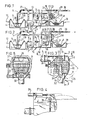
- the stone catcher 7 shown in Figures 3 to 5 comprises a grid basket 22 which is fixedly connected with a shaft 32 pivotally journalled in the housing 17, which can be turned by means of a hydraulic cylinder 33 acting on an arm 34 of the shaft 32 in order to turn the grid basket 22 into the position indicated by broken lines, when the door 20 is opened.
- the door 20 is pivotable about a pivotal shaft 35 by means of a hydraulic cylinder 36.
- the grid basket 22 has a stone outlet 25, which is closed by the door 20 during the. suction process so that in the position indicated by broken lines the grid basket 22 is open on the bottom side.
- the grid basket 22 has furthermore an inlet opening 37 communicating with the spoil feed 18 and having a size at least equal to the passage of the suction pipe 3.
- the grid basket 22 of Figure 3 can be turned by means of the discharge means formed by the cylinder 33 between a working position indicated by solid lines in the housing 17 and a discharge position indicated in Figure 3 by broken lines outside the housing 17.
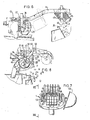
- Figure 6 shows that it is also possible, however, to convey the grid basket 22 out of the housing 17, when the door 20 is opened, by means of a grab 38, which is tiltably suspended to a grab carriage 39.
- a movable clamping jaw 41 can grasp the grid basket 22 by means of a hydraulic cylinder 42 after which the grab carriage 39 is displaced by means of an electric driving motor 43 along a rail 44 extending out of the board and beyond it to a higher level.
- the grid basket 22 is tilted about a low-level tilting shaft 40 by means of a hydraulic cylinder 45 so that the stones 8 can drop from the basket 22 through the stone outlet 25 into a stone trough 30, which may be high.
- the stone catcher 7 of Figures 7 and 8 comprises a grid basket 22 formed by a flexible net 46, which is deformable between a basket-like working state indicated in Figure 8 by broken lines and a straight discharge state indicated in said Figure by broken lines.
- the net 46 is pivoted at one end 47 near the spoil inlet 18 to the housing 17 around a shaft 48 and is wound around two end discs 49, whilst its other end 50 is secured to discs 49 around a shaft 51.
- two grabs 52 grasp by their movable clamping jaws 54 energized by a hydraulic cylinder 53 stub shafts 55 of the discs 49.
- each disc 49 has pivoted to it an arm 59, which is pivotable about a hinge 60.
- This arm 59 is supported by a stationary lug 61 of the associated disc 49 and is acted upon by an air spring 62 in the form of a pneumatic cylinder, which urges the arm 59 against the lug 61.
- the stone catcher 7 of Figures 12 to 14 has a grid basket 22 which is rigidly connected with the door 20 so that at the turn of the door 20 the grid basket 22 is directly moved through the stone outlet opening 21 of the housing 17 into the discharge position indicated in Figure 14 by broken lines by means of a hydraulic cylinder 63.
- the stone outlet 25 of the grid basket 22 slides along a perforated, stationary bottom 64 of the housing 17.
- the scoop dredger 1 preferably comprises two stone catchers 7 arranged side by side and connected with a common suction pipe 3 through a displaceable nozzle 65 arranged near the stone catchers 7 and alternately opening out in one of the two spoil inlets 18 of these stone catchers 7 .
- the nozzle 65 is adapted to turn about a pivotal shaft 66 by means of an arm 67 with the aid of a hydraulic cylinder 68.
- the nozzle 65 is arranged between two flaps 70 closing the housings 17 by means of a hydraulic cylinder 69 each.
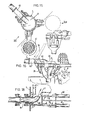
- the stone catcher 7 indicated on the left-hand side is included in the suction pipe 3 as indicated in Figure 11.
- the right-hand stone catcher 7 can be relieved from the collected stones 8, when the door 20 is opened, by turning the grid basket 22 with the aid of the hydraulic cylinder 33 about the shaft 32.
- the right-hand stone catcher 7 can be filled with water whilst it is vented through a vent valve 75.
- the flaps 70 are preferably replaced by slides 76 as shown in the variant of the detail of Figure 18.
- a knife 77 may be provided which co-operates in scissor-like fashion with a counter-knife 78 in order to cut off any elongated object extending from the nozzle 65 into the grid basket 22, for example, a steel wire when the stone catcher housing 17 is closed by the slide 76. It is thus ensured that the nozzle 65 can be turned about its longitudinal axis 79.
- the slides 76 are actuated by high-power hydraulic cylinders 80.
- the stone catcher 7 of Figures 15 to 17 comprises a stone catcher housing 17 having two grid baskets 22 alternately located inside and outside the housing 17.
- Each grid basket 22 has at the top end a ring 81 joining the housing 17 and forming a junction between the housing 17 and the door 20.
- a grid basket 22 can be turned by means of hydraulic cylinders 33 out of the housing 17 and be tilted over for discharging the stones 8 along the top side into a stone trough 30.
- the spoil inlet 18 communicates on the one hand with an opening 82 of the door 20 and on the other hand through a hose 83 with the suction pipe 3 so that the door 20 can be turned by means of hydraulic cylinders 36, whilst the connection of the suction pipe 3 with the door 20 is maintained.
- Figure 15 shows that the grid baskets 22 can be turned in orthogonal positions beyond the board as far as above a high stone trough 30.
- the filling duct 15 may be used, if desired, as a flushing duct with substantially all stone catchers 7 in order to loosen the stones 8 by the flow from the meshes of the grid basket 22 opposite the direction 28.
Landscapes
- Engineering & Computer Science (AREA)
- General Engineering & Computer Science (AREA)
- Mechanical Engineering (AREA)
- Mining & Mineral Resources (AREA)
- Civil Engineering (AREA)
- Structural Engineering (AREA)
- Filtration Of Liquid (AREA)
Applications Claiming Priority (2)
| Application Number | Priority Date | Filing Date | Title |
|---|---|---|---|
| NL7800935 | 1978-01-26 | ||
| NLAANVRAGE7800935,A NL172977C (nl) | 1978-01-26 | 1978-01-26 | Baggertransportleiding met stenenvanger. |
Publications (2)
| Publication Number | Publication Date |
|---|---|
| EP0003384A1 true EP0003384A1 (de) | 1979-08-08 |
| EP0003384B1 EP0003384B1 (de) | 1981-11-18 |
Family
ID=19830227
Family Applications (1)
| Application Number | Title | Priority Date | Filing Date |
|---|---|---|---|
| EP79200040A Expired EP0003384B1 (de) | 1978-01-26 | 1979-01-23 | Förderleitung für Saugbaggeranlage |
Country Status (5)
| Country | Link |
|---|---|
| US (1) | US4250034A (de) |
| EP (1) | EP0003384B1 (de) |
| JP (1) | JPS54110634A (de) |
| DE (1) | DE2961341D1 (de) |
| NL (1) | NL172977C (de) |
Cited By (3)
| Publication number | Priority date | Publication date | Assignee | Title |
|---|---|---|---|---|
| US4319782A (en) * | 1980-06-06 | 1982-03-16 | Deepsea Ventures, Inc. | Means for controlling feed of particulate material into airlift pipe |
| CN112031055A (zh) * | 2020-09-02 | 2020-12-04 | 仙桃市水利水电工程安装有限公司 | 防堵水利清淤装置及其应用方法 |
| CN112575839A (zh) * | 2020-12-23 | 2021-03-30 | 长沙理工大学 | 一种清淤机器人 |
Families Citing this family (9)
| Publication number | Priority date | Publication date | Assignee | Title |
|---|---|---|---|---|
| US4605497A (en) * | 1985-09-03 | 1986-08-12 | Toyo Denki Kogyosho Co., Ltd. | Device for processing fluid with solid bodies |
| US5037545A (en) * | 1989-02-27 | 1991-08-06 | Billmyre Richard D | Liquid recovery system and method |
| US5141650A (en) * | 1989-10-04 | 1992-08-25 | County Line Sand & Gravel, Inc. | Pressure screen |
| US6003251A (en) * | 1998-07-23 | 1999-12-21 | The United States Of America As Represented By The Secretary Of The Army | Debris separator for dredge or slurry pump |
| CN109914504B (zh) * | 2019-04-12 | 2023-10-10 | 中交(天津)疏浚工程有限公司 | 带有震动型格栅的耙吸挖泥船耙头结构 |
| US11828042B2 (en) | 2020-05-25 | 2023-11-28 | Wing Marine Llc | Material handling systems and methods |
| CN111841091B (zh) * | 2020-06-16 | 2021-12-07 | 中交第三公路工程局有限公司 | 排泥设施 |
| CN116078017A (zh) * | 2022-12-15 | 2023-05-09 | 中交疏浚技术装备国家工程研究中心有限公司 | 一种耙吸挖泥船进舱泥浆过滤排水方法及其实施装置 |
| US12398532B2 (en) | 2024-01-19 | 2025-08-26 | Wing Marine Llc | Marine vessels and methods of using same |
Citations (3)
| Publication number | Priority date | Publication date | Assignee | Title |
|---|---|---|---|---|
| NL82972C (de) | ||||
| US1646514A (en) | 1925-04-18 | 1927-10-25 | Mechanical Appliance Company | Water-line trap |
| DE731697C (de) | 1940-12-03 | 1943-02-13 | Karl Heinz Schoerling | Saugbagger mit Steinkasten |
Family Cites Families (3)
| Publication number | Priority date | Publication date | Assignee | Title |
|---|---|---|---|---|
| US1950983A (en) * | 1930-08-04 | 1934-03-13 | Hennebohle Frank | Strainer |
| US2019169A (en) * | 1934-02-17 | 1935-10-29 | Backlund Knute | Strainer |
| US2068468A (en) * | 1934-03-31 | 1937-01-19 | Pratt Co Henry | Filter |
-
1978
- 1978-01-26 NL NLAANVRAGE7800935,A patent/NL172977C/xx not_active IP Right Cessation
-
1979
- 1979-01-23 EP EP79200040A patent/EP0003384B1/de not_active Expired
- 1979-01-23 DE DE7979200040T patent/DE2961341D1/de not_active Expired
- 1979-01-23 US US06/005,716 patent/US4250034A/en not_active Expired - Lifetime
- 1979-01-26 JP JP866579A patent/JPS54110634A/ja active Pending
Patent Citations (3)
| Publication number | Priority date | Publication date | Assignee | Title |
|---|---|---|---|---|
| NL82972C (de) | ||||
| US1646514A (en) | 1925-04-18 | 1927-10-25 | Mechanical Appliance Company | Water-line trap |
| DE731697C (de) | 1940-12-03 | 1943-02-13 | Karl Heinz Schoerling | Saugbagger mit Steinkasten |
Cited By (3)
| Publication number | Priority date | Publication date | Assignee | Title |
|---|---|---|---|---|
| US4319782A (en) * | 1980-06-06 | 1982-03-16 | Deepsea Ventures, Inc. | Means for controlling feed of particulate material into airlift pipe |
| CN112031055A (zh) * | 2020-09-02 | 2020-12-04 | 仙桃市水利水电工程安装有限公司 | 防堵水利清淤装置及其应用方法 |
| CN112575839A (zh) * | 2020-12-23 | 2021-03-30 | 长沙理工大学 | 一种清淤机器人 |
Also Published As
| Publication number | Publication date |
|---|---|
| US4250034A (en) | 1981-02-10 |
| EP0003384B1 (de) | 1981-11-18 |
| NL172977B (nl) | 1983-06-16 |
| NL7800935A (nl) | 1979-07-30 |
| DE2961341D1 (en) | 1982-01-21 |
| JPS54110634A (en) | 1979-08-30 |
| NL172977C (nl) | 1983-11-16 |
Similar Documents
| Publication | Publication Date | Title |
|---|---|---|
| EP0003384B1 (de) | Förderleitung für Saugbaggeranlage | |
| US5425188A (en) | Suction excavator | |
| CA1132766A (en) | Mobile vacuum loader | |
| US5021156A (en) | Dump truck for receiving draining and disposing of dredged material | |
| US4627781A (en) | Bag cutting-and emptying-device with connected collective dust-removal filter | |
| US4121915A (en) | Vacuum cleaning apparatus | |
| US8191202B2 (en) | Mobile vacuum apparatus for collection of liquid or semi-liquid materials | |
| US4017281A (en) | Industrial vacuum loader with dust removal means for bag house filtration system | |
| CA1102970A (en) | Apparatus for sewer cleaning and the like | |
| US2917761A (en) | Street sweeper hopper and lift mechanism | |
| GB1592775A (en) | Refuse collecting vehicles | |
| EP0029469A1 (de) | Baggerverfahren und Baggerausrüstung | |
| US6669841B2 (en) | Marine vessel for collecting floating debris | |
| US5060404A (en) | Auger type dredging head | |
| US3748760A (en) | Dredging machinery with swinging double ended scoop | |
| US3193867A (en) | Street cleaning apparatus | |
| EP0075358B1 (de) | Verfahren zum Aufsaugen von Boden oder Schlamm mittels eines Saugbaggers mit Laderaum und ein Saugbagger zur Ausführung des Verfahrens | |
| US3222706A (en) | Sweeping machine | |
| US4398576A (en) | Packer-filler machine | |
| CN115382836A (zh) | 一种玉米粒清洗去杂设备 | |
| US4216997A (en) | Grab excavator with fixed jib | |
| US4318621A (en) | Transit concrete mixer with displaceable charging hopper | |
| EP0023235B1 (de) | Wasserfahrzeug zum Transport von Baggergut | |
| CN214531958U (zh) | 一种新型混凝土吊料斗 | |
| JP2003213719A (ja) | 吸引機能を備えたショベルバケットとそのバケットを有する作業機械 |
Legal Events
| Date | Code | Title | Description |
|---|---|---|---|
| PUAI | Public reference made under article 153(3) epc to a published international application that has entered the european phase |
Free format text: ORIGINAL CODE: 0009012 |
|
| AK | Designated contracting states |
Designated state(s): DE FR GB IT SE |
|
| 17P | Request for examination filed | ||
| ITF | It: translation for a ep patent filed | ||
| GRAA | (expected) grant |
Free format text: ORIGINAL CODE: 0009210 |
|
| AK | Designated contracting states |
Designated state(s): DE FR GB IT SE |
|
| REF | Corresponds to: |
Ref document number: 2961341 Country of ref document: DE Date of ref document: 19820121 |
|
| PGFP | Annual fee paid to national office [announced via postgrant information from national office to epo] |
Ref country code: DE Payment date: 19831227 Year of fee payment: 6 |
|
| PGFP | Annual fee paid to national office [announced via postgrant information from national office to epo] |
Ref country code: FR Payment date: 19840125 Year of fee payment: 6 |
|
| PGFP | Annual fee paid to national office [announced via postgrant information from national office to epo] |
Ref country code: SE Payment date: 19840331 Year of fee payment: 6 |
|
| PG25 | Lapsed in a contracting state [announced via postgrant information from national office to epo] |
Ref country code: SE Effective date: 19850124 |
|
| GBPC | Gb: european patent ceased through non-payment of renewal fee | ||
| PG25 | Lapsed in a contracting state [announced via postgrant information from national office to epo] |
Ref country code: FR Free format text: LAPSE BECAUSE OF NON-PAYMENT OF DUE FEES Effective date: 19850930 |
|
| PG25 | Lapsed in a contracting state [announced via postgrant information from national office to epo] |
Ref country code: DE Effective date: 19851001 |
|
| REG | Reference to a national code |
Ref country code: FR Ref legal event code: ST |
|
| PG25 | Lapsed in a contracting state [announced via postgrant information from national office to epo] |
Ref country code: GB Effective date: 19881117 |
|
| EUG | Se: european patent has lapsed |
Ref document number: 79200040.8 Effective date: 19860129 |
|
| PLBE | No opposition filed within time limit |
Free format text: ORIGINAL CODE: 0009261 |
|
| STAA | Information on the status of an ep patent application or granted ep patent |
Free format text: STATUS: NO OPPOSITION FILED WITHIN TIME LIMIT |