EP0003675A1 - Dispositif de mesure de la pression - Google Patents
Dispositif de mesure de la pression Download PDFInfo
- Publication number
- EP0003675A1 EP0003675A1 EP79300187A EP79300187A EP0003675A1 EP 0003675 A1 EP0003675 A1 EP 0003675A1 EP 79300187 A EP79300187 A EP 79300187A EP 79300187 A EP79300187 A EP 79300187A EP 0003675 A1 EP0003675 A1 EP 0003675A1
- Authority
- EP
- European Patent Office
- Prior art keywords
- block
- pipe
- blocks
- arc
- face
- Prior art date
- Legal status (The legal status is an assumption and is not a legal conclusion. Google has not performed a legal analysis and makes no representation as to the accuracy of the status listed.)
- Withdrawn
Links
- 238000005452 bending Methods 0.000 claims abstract description 4
- 230000000737 periodic effect Effects 0.000 claims abstract description 3
- 239000013078 crystal Substances 0.000 claims description 7
- 229910052751 metal Inorganic materials 0.000 claims description 3
- 239000002184 metal Substances 0.000 claims description 3
- 239000011347 resin Substances 0.000 claims 2
- 229920005989 resin Polymers 0.000 claims 2
- 230000010339 dilation Effects 0.000 claims 1
- 239000000446 fuel Substances 0.000 abstract description 16
- 239000000463 material Substances 0.000 description 8
- 239000004033 plastic Substances 0.000 description 5
- 229920003023 plastic Polymers 0.000 description 5
- 229910000838 Al alloy Inorganic materials 0.000 description 2
- 229910045601 alloy Inorganic materials 0.000 description 2
- 239000000956 alloy Substances 0.000 description 2
- 238000010276 construction Methods 0.000 description 2
- 230000001419 dependent effect Effects 0.000 description 2
- 229920003319 Araldite® Polymers 0.000 description 1
- 229910001369 Brass Inorganic materials 0.000 description 1
- BQCADISMDOOEFD-UHFFFAOYSA-N Silver Chemical compound [Ag] BQCADISMDOOEFD-UHFFFAOYSA-N 0.000 description 1
- 239000000853 adhesive Substances 0.000 description 1
- 230000001070 adhesive effect Effects 0.000 description 1
- 230000002238 attenuated effect Effects 0.000 description 1
- 239000010951 brass Substances 0.000 description 1
- 230000007797 corrosion Effects 0.000 description 1
- 238000005260 corrosion Methods 0.000 description 1
- 229920006332 epoxy adhesive Polymers 0.000 description 1
- 239000003822 epoxy resin Substances 0.000 description 1
- 238000003754 machining Methods 0.000 description 1
- 238000004519 manufacturing process Methods 0.000 description 1
- 229920000647 polyepoxide Polymers 0.000 description 1
- 230000008439 repair process Effects 0.000 description 1
- 229910052709 silver Inorganic materials 0.000 description 1
- 239000004332 silver Substances 0.000 description 1
- 229920001187 thermosetting polymer Polymers 0.000 description 1
Images


Classifications
-
- F—MECHANICAL ENGINEERING; LIGHTING; HEATING; WEAPONS; BLASTING
- F02—COMBUSTION ENGINES; HOT-GAS OR COMBUSTION-PRODUCT ENGINE PLANTS
- F02M—SUPPLYING COMBUSTION ENGINES IN GENERAL WITH COMBUSTIBLE MIXTURES OR CONSTITUENTS THEREOF
- F02M65/00—Testing fuel-injection apparatus, e.g. testing injection timing ; Cleaning of fuel-injection apparatus
- F02M65/003—Measuring variation of fuel pressure in high pressure line
-
- G—PHYSICS
- G01—MEASURING; TESTING
- G01L—MEASURING FORCE, STRESS, TORQUE, WORK, MECHANICAL POWER, MECHANICAL EFFICIENCY, OR FLUID PRESSURE
- G01L23/00—Devices or apparatus for measuring or indicating or recording rapid changes, such as oscillations, in the pressure of steam, gas, or liquid; Indicators for determining work or energy of steam, internal-combustion, or other fluid-pressure engines from the condition of the working fluid
- G01L23/08—Devices or apparatus for measuring or indicating or recording rapid changes, such as oscillations, in the pressure of steam, gas, or liquid; Indicators for determining work or energy of steam, internal-combustion, or other fluid-pressure engines from the condition of the working fluid operated electrically
- G01L23/10—Devices or apparatus for measuring or indicating or recording rapid changes, such as oscillations, in the pressure of steam, gas, or liquid; Indicators for determining work or energy of steam, internal-combustion, or other fluid-pressure engines from the condition of the working fluid operated electrically by pressure-sensitive members of the piezoelectric type
-
- G—PHYSICS
- G01—MEASURING; TESTING
- G01L—MEASURING FORCE, STRESS, TORQUE, WORK, MECHANICAL POWER, MECHANICAL EFFICIENCY, OR FLUID PRESSURE
- G01L23/00—Devices or apparatus for measuring or indicating or recording rapid changes, such as oscillations, in the pressure of steam, gas, or liquid; Indicators for determining work or energy of steam, internal-combustion, or other fluid-pressure engines from the condition of the working fluid
- G01L23/24—Devices or apparatus for measuring or indicating or recording rapid changes, such as oscillations, in the pressure of steam, gas, or liquid; Indicators for determining work or energy of steam, internal-combustion, or other fluid-pressure engines from the condition of the working fluid specially adapted for measuring pressure in inlet or exhaust ducts of internal-combustion engines
Definitions
- This invention relates to apparatus for sensing cyclically varying pressure in a pipe, for example a fuel line to an injector on a diesel engine.
- Fuel pressure variations in a diesel engine can give important information about the running of the engine and possible adjustments and repairs. It is in the highest degree undesirable to interfere with the integrity of the fuel lines.
- British Patent No. 1 506 701 apparatus is described which can be clamped about a union in the fuel line.
- the main object of the invention is to provide a simple and compact form of apparatus which can sense fuel line pressure externally, more particularly but not exclusively for automotive applications.
- the invention provides apparatus for sensing cyclically varying pressure in a pipe comprising a pair of similar blocks shaped to embrace a pipe over an arc and to make line contact with the pipe at two spaced locations, means to clamp the blocks about a pipe, and a transducer on-each block to provide electrical signals in dependence on strain in the block due to periodic dilatation of the pipe.
- the blocks are mounted in similar holders such that when clamped together about the pipe the blocks are spaced apart.
- the blocks are conveniently located in cavities in the holders in which they are surrounded with plastics material having elastic properties: this material may be cast around the blocks. Clamping the holders loads the blocks so that in operation each block acts as an arch supported at the spaced locations and loaded over its length.
- the transducer is preferably located at the top of the arch, being cemented on to the top surface of the block. By varying the central section and the loading the strain for a given pressure variation can be altered.
- the form of pressure sensing apparatus there shown comprises a pair of similar rigid metallic holders designated generally 301, 302 which in use of the apparatus are clamped around a fuel pipe 303 (shown in Figure 5A) by means of a pair of screws 304.
- the holders define a central cylindrical aperture 305, as shown in Figures 1 and 2, and the fuel line extends through this.
- the holders, 301, 302 seen in transverse section each define a generally cylindrical cavity or space 306.
- the cavities 306 of the two holders are aligned with their common axis at right angles to the axis of the fuel line.
- a metallic block 307 adapted to bear on the fuel line 33 is located coaxially in each cavity 306, with clearance at the bottom and sides of the cavity.
- the blocks 307 are each cylindrical, with their axes aligned on that of the cavities 306.
- One face 307a of the block 307 is generally concave and bears on the fuel line as will be described.
- a piezo-electric transducer element 308 extends over the whole circular-area of the other face 307b of the block and is cemented thereto in electrical contact therewith.
- a connecting wire 309 is taken from the free face of the transducer element 308 to a terminal on a bayonet connector 312-mounted on the holder. It will be seen that the clearance between the block 307 and the piezo-electric element 308, and the bottom of the cavity 306, is of the same order as the depth of the block and element. The clearance between the sides of the block and the side walls of the cavity is much less.
- the block 307 is conveniently of the aluminium alloy available under the designation DURAL HE 30TF as defined in British Standard Specification 1470. This alloy combines freedom from corrosion and easy machining with a modulus of elasticity which for a metal is fairly low. Alternatively the block could be made of brass.
- the holders 301, 302 can be made of the same aluminium alloy, though for the holder the choice of material is less critical.
- This material is, for a plastics material, relatively hard and elastic; but its hardness and modulus of elasticity are much less than that of the alloy of the blocks 307.
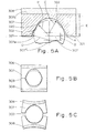
- Each block 307 has its concave face 307a formed on two radii one, shown at C, less than the pipe outside radius R and the other, D, greater than this, as shown in Figure 5A.
- the blocks 307 make virtual contact on a diametual plane 307' of the pipe; this-is also part of the envelope surface of the block.
- the smaller radius C is centred within the envelope surface 307' by a distance A.
- the larger radius D is centred outside the envelope 307' by a distance B.
- Both the centres of radii C and D and the centre of the pipe lie on the vertical centre line 307" of the block so as to give a symmetrical arrangement.
- Each block 307 embraces some 180° of the pipe.
- the arcs 320 and 321, 321 formed on the radii C and D respectively intersect to form cusps 322, 322 at 30° and 150°. It is at these points 322, 322 that the block 307 bears upon the pipe.
- each cavity 306 is 12 mm in diameter and 12 mm deep, and each block 307 is 10 mm in diameter.
- the preferred dimensions for various pipe diameters are as follows:-
- the radius D is the less critical of the two, C and D. While it is considered best to have the block bear at the points 30° and 150°; some variation is permissible, more especially the points 322 could be moved outwards towards the ends of the 180° arc of embrace.
- Each block 307 acts as a bending arch supported at the points 322 and uniformly loaded on top.
- the deformation of the blocks 307 on dilatation of the pipe 303 is illustrated in an exaggerated manner in Figures 5B and 5C.
- the shape of the block can be designed for optimum response. For example, the section at the top of the arch can be reduced.
- the block need not have a flat top, but can be symmetrically sloped or rounded.
- each block 307 can be supported by plastics material at its sides only, and not at the bottom of the cavity.
- the plastics material applies shear forces to the sides of the block and the loading of the arch is therefore different.
- the block 307 could be supported by plastics material at the bottom of the cavity, not at the sides. The arrangement illustrated is, however, easy to make and robust.
- the apparatus can readily be bolted on or removed from a fuel line of a small compact engine. It can be secured to each of the fuel lines of an engine in turn.
- the device illustrated can be used with an engine cylinder pressure sensing device, if the engine cylinder pressure is accessible, as it is on larger or experimentally adapted engines.
- the cylinder pressure can be obtained by a closed-end tube which can be connected to the cylinder and a second pressure sensing device mounted thereon. This device can be as previously described. Pressure-dependent signals from the second device are then injected into the analysing circuit referred to.
Landscapes
- Engineering & Computer Science (AREA)
- Chemical & Material Sciences (AREA)
- Combustion & Propulsion (AREA)
- Physics & Mathematics (AREA)
- General Physics & Mathematics (AREA)
- Mechanical Engineering (AREA)
- General Engineering & Computer Science (AREA)
- Fuel-Injection Apparatus (AREA)
- Measuring Fluid Pressure (AREA)
Applications Claiming Priority (2)
| Application Number | Priority Date | Filing Date | Title |
|---|---|---|---|
| GB513278 | 1978-02-08 | ||
| GB513278 | 1978-02-08 |
Publications (1)
| Publication Number | Publication Date |
|---|---|
| EP0003675A1 true EP0003675A1 (fr) | 1979-08-22 |
Family
ID=9790312
Family Applications (1)
| Application Number | Title | Priority Date | Filing Date |
|---|---|---|---|
| EP79300187A Withdrawn EP0003675A1 (fr) | 1978-02-08 | 1979-02-07 | Dispositif de mesure de la pression |
Country Status (1)
| Country | Link |
|---|---|
| EP (1) | EP0003675A1 (fr) |
Cited By (1)
| Publication number | Priority date | Publication date | Assignee | Title |
|---|---|---|---|---|
| EP0052957A1 (fr) * | 1980-11-21 | 1982-06-02 | Imperial Chemical Industries Plc | Méthode et appareil pour la détection de fuites dans des pipelines |
Citations (7)
| Publication number | Priority date | Publication date | Assignee | Title |
|---|---|---|---|---|
| FR2035042A1 (fr) * | 1969-03-18 | 1970-12-18 | Beatson Engineering Cy L | |
| US3603152A (en) * | 1970-02-05 | 1971-09-07 | Columbia Research Lab Inc | Transducer for detecting pressure changes in fluid flow |
| GB1372030A (en) * | 1971-12-30 | 1974-10-30 | Cav Ltd | Transducers |
| US3886473A (en) * | 1974-06-13 | 1975-05-27 | Hans D Heyck | Capacitive pressure and displacement transducers |
| US3942049A (en) * | 1973-08-30 | 1976-03-02 | Ckd Praha, Oborovy Podnik | Piezoelectric pick-up device for measuring pressures within hollow bodies |
| DE2533078A1 (de) * | 1975-07-24 | 1977-02-10 | Kromberg Ges Fuer Ingenieurlei | Vorrichtung zum messen von druecken |
| FR2322365A1 (fr) * | 1975-08-28 | 1977-03-25 | Siemens Ag | Capteur piezoelectrique de pression |
-
1979
- 1979-02-07 EP EP79300187A patent/EP0003675A1/fr not_active Withdrawn
Patent Citations (7)
| Publication number | Priority date | Publication date | Assignee | Title |
|---|---|---|---|---|
| FR2035042A1 (fr) * | 1969-03-18 | 1970-12-18 | Beatson Engineering Cy L | |
| US3603152A (en) * | 1970-02-05 | 1971-09-07 | Columbia Research Lab Inc | Transducer for detecting pressure changes in fluid flow |
| GB1372030A (en) * | 1971-12-30 | 1974-10-30 | Cav Ltd | Transducers |
| US3942049A (en) * | 1973-08-30 | 1976-03-02 | Ckd Praha, Oborovy Podnik | Piezoelectric pick-up device for measuring pressures within hollow bodies |
| US3886473A (en) * | 1974-06-13 | 1975-05-27 | Hans D Heyck | Capacitive pressure and displacement transducers |
| DE2533078A1 (de) * | 1975-07-24 | 1977-02-10 | Kromberg Ges Fuer Ingenieurlei | Vorrichtung zum messen von druecken |
| FR2322365A1 (fr) * | 1975-08-28 | 1977-03-25 | Siemens Ag | Capteur piezoelectrique de pression |
Cited By (1)
| Publication number | Priority date | Publication date | Assignee | Title |
|---|---|---|---|---|
| EP0052957A1 (fr) * | 1980-11-21 | 1982-06-02 | Imperial Chemical Industries Plc | Méthode et appareil pour la détection de fuites dans des pipelines |
Similar Documents
| Publication | Publication Date | Title |
|---|---|---|
| US4257260A (en) | Pressure sensing apparatus and engine analyzing apparatus | |
| US3970878A (en) | Piezoelectric transducer unit and hydrophone assembly | |
| US5545984A (en) | Damping device for sonic waveguides | |
| US3213400A (en) | Membrane-type strain gauge | |
| EP0033749B1 (fr) | Cellule de mesure de la pression piézorésistive en forme de boîte cylindrique | |
| US6239393B1 (en) | Contact device and a tool for handling it | |
| US5512794A (en) | Shear accelerometer | |
| EP1642106A1 (fr) | Dispositif de mesure d'une force de precontrainte dans une piece ecrou de boulon | |
| US4088916A (en) | Piezoelectric pressure pickup | |
| US5144841A (en) | Device for measuring pressures and forces | |
| US5680041A (en) | Magnetostrictive position measurement apparatus with anti-reflection waveguide terminals | |
| EP0003675A1 (fr) | Dispositif de mesure de la pression | |
| US5572081A (en) | Accelerometer | |
| US4611141A (en) | Lead structure for a piezoelectric array-type ultrasonic probe | |
| US4710744A (en) | Pressure transducer package | |
| JPH0368827A (ja) | 力測定器 | |
| US4926397A (en) | Depth alarm for a seismic sensor | |
| US3313962A (en) | Piezo-electric transducer | |
| US4652785A (en) | Acoustic piezoelectric power transducer | |
| US3473386A (en) | Fluid fitting mounted pressure transducer | |
| US4392374A (en) | Transducer coupling apparatus for inhomogeneity detector | |
| JPS60224035A (ja) | 圧力変換器および取付体 | |
| US3710151A (en) | Electroacoustic transducer for use at high temperatures and pressures | |
| JPS649331A (en) | Structure of pressure sensor | |
| JPS5951326A (ja) | 力トランスジユ−サ |
Legal Events
| Date | Code | Title | Description |
|---|---|---|---|
| PUAI | Public reference made under article 153(3) epc to a published international application that has entered the european phase |
Free format text: ORIGINAL CODE: 0009012 |
|
| STAA | Information on the status of an ep patent application or granted ep patent |
Free format text: STATUS: THE APPLICATION HAS BEEN PUBLISHED |
|
| AK | Designated contracting states |
Designated state(s): BE DE FR IT LU NL SE |
|
| 18RR | Decision to grant the request for re-establishment of rights before grant | ||
| R18X | Re-established (corrected) | ||
| 110E | Request filed for conversion into a national patent application [according to art. 135 epc] | ||
| 18D | Application deemed to be withdrawn | ||
| RIN1 | Information on inventor provided before grant (corrected) |
Inventor name: NUNN, TERENCE MICHAEL Inventor name: BEATSON, MICHAEL FRAME FULLARTON |