EP0003994B1 - Serrure, en particulier pour une colonne de direction de véhicule - Google Patents
Serrure, en particulier pour une colonne de direction de véhicule Download PDFInfo
- Publication number
- EP0003994B1 EP0003994B1 EP19790100509 EP79100509A EP0003994B1 EP 0003994 B1 EP0003994 B1 EP 0003994B1 EP 19790100509 EP19790100509 EP 19790100509 EP 79100509 A EP79100509 A EP 79100509A EP 0003994 B1 EP0003994 B1 EP 0003994B1
- Authority
- EP
- European Patent Office
- Prior art keywords
- key
- bolt
- barrel
- receiving slot
- lock
- Prior art date
- Legal status (The legal status is an assumption and is not a legal conclusion. Google has not performed a legal analysis and makes no representation as to the accuracy of the status listed.)
- Expired
Links
Images

Classifications
-
- B—PERFORMING OPERATIONS; TRANSPORTING
- B60—VEHICLES IN GENERAL
- B60R—VEHICLES, VEHICLE FITTINGS, OR VEHICLE PARTS, NOT OTHERWISE PROVIDED FOR
- B60R25/00—Fittings or systems for preventing or indicating unauthorised use or theft of vehicles
- B60R25/01—Fittings or systems for preventing or indicating unauthorised use or theft of vehicles operating on vehicle systems or fittings, e.g. on doors, seats or windscreens
- B60R25/02—Fittings or systems for preventing or indicating unauthorised use or theft of vehicles operating on vehicle systems or fittings, e.g. on doors, seats or windscreens operating on the steering mechanism
- B60R25/021—Fittings or systems for preventing or indicating unauthorised use or theft of vehicles operating on vehicle systems or fittings, e.g. on doors, seats or windscreens operating on the steering mechanism restraining movement of the steering column or steering wheel hub, e.g. restraining means controlled by ignition switch
- B60R25/0211—Fittings or systems for preventing or indicating unauthorised use or theft of vehicles operating on vehicle systems or fittings, e.g. on doors, seats or windscreens operating on the steering mechanism restraining movement of the steering column or steering wheel hub, e.g. restraining means controlled by ignition switch comprising a locking member radially and linearly moved towards the steering column
- B60R25/02115—Fittings or systems for preventing or indicating unauthorised use or theft of vehicles operating on vehicle systems or fittings, e.g. on doors, seats or windscreens operating on the steering mechanism restraining movement of the steering column or steering wheel hub, e.g. restraining means controlled by ignition switch comprising a locking member radially and linearly moved towards the steering column key actuated
- B60R25/02118—Fittings or systems for preventing or indicating unauthorised use or theft of vehicles operating on vehicle systems or fittings, e.g. on doors, seats or windscreens operating on the steering mechanism restraining movement of the steering column or steering wheel hub, e.g. restraining means controlled by ignition switch comprising a locking member radially and linearly moved towards the steering column key actuated with linear bolt motion parallel to the lock axis
- B60R25/02121—Fittings or systems for preventing or indicating unauthorised use or theft of vehicles operating on vehicle systems or fittings, e.g. on doors, seats or windscreens operating on the steering mechanism restraining movement of the steering column or steering wheel hub, e.g. restraining means controlled by ignition switch comprising a locking member radially and linearly moved towards the steering column key actuated with linear bolt motion parallel to the lock axis comprising safety devices avoiding locking until removal of the key
Definitions
- This invention relates to a lock of the kind comprising a body, a bolt which is movable relative to the body between locking and releasing positions, in the former of which positions the bolt projects from the body to engage with a member, the movement of which is to be restricted or prevented by the lock, and in the latter of which positions the bolt is withdrawn from said member, a key-operated lock mechanism for moving the bolt between the locking position and the releasing position, the lock mechanism including a barrel having a key-receiving slot with an open end at a face of the barrel called herein the front face and the barrel being rotatable relative to the body when the proper key is present in the key-receiving slot, and the lock further comprising a retaining element which moves with the bolt between the locking and releasing positions, the barrel having at its end remote from its front face retaining means engageable with the retaining element to hold the bolt temporarily in its releasing position.
- the key In order to minimise wear of the tumblers, it is usual to form the key of a fairly soft material. During withdrawal of the key, the key is in rubbing contact under high pressure with the tumbler which is required to rock the pawl away from the barrel. Because the key is required to exert a large force on the tumbler, excessive wear of the key is likely to occur. This leads to decreased ability of the key to cause the tumbler to project from the barrel and gives rise to a risk that the key may be withdrawn whilst the pawl remains in engagement with the forwardly facing surface of the flange, thereby holding the bolt in its releasing position.
- the retaining means of a lock of the kind referred to defines a recess into which the retaining element enters when the bolt moves to its locking position.
- This recess avoids the necessity for the retaining element to be pushed away from the barrel beyond the periphery of the retaining means during withdrawal of the key.
- a further disadvantage of the lock described in French Specification 2,131,688 is that the pawl and its spring occupy a fairly large space at one side of the barrel. A consequence of this is that the transverse dimensions of the lock are fairly large and this makes it difficult to incorporate the lock in some apparatus which is required to be controlled by a lock of the kind referred to.
- the entire retaining element when disposed in the recess of the retaining means, preferably lies nearer to an axis of rotation of the barrel than does a radially outer part of the retaining means. With this arrangement, the retaining element does not extend further from the barrel than does the retaining means and the cross-sectional dimensions of the lock can be smaller than the corresponding dimensions of the lock described in the aforesaid French Specification.
- a lock in accordance with the present invention preferably includes also a key-detecting element mounted in the barrel for movement relative thereto into and out of the key-receiving slot and an abutment mounted on the bolt for rocking relative to the bolt towards and away from the key-receiving slot about a rocking axis, the arrangement being such that, when the key-detecting element is out of the key-receiving slot, it projects radially from the barrel into the path of the abutment on the bolt to obstruct movement of the bolt from the releasing position into the locking position until the key is withdrawn and the key-detecting element is permitted to move into the key-receiving slot, the abutment being constrained to move with the bolt between the locking and releasing positions and being movable relative to the bolt in a direction away from the key-receiving slot, the rocking axis of the abutment being spaced, in all positions of the bolt, in the same general direction from a face of the key-detecting element which is engaged by the
- the bolt is retained in its releasing position even when the retaining element is aligned with the recess in the retaining means until the key is withdrawn, without reinsertion of the key being obstructed in the event that the bolt is prevented from moving fully into its locking position, thereby arresting the abutment in a position where it will be engaged by the key-detecting element when that element is expelled from the key-receiving slot by insertion of the key.
- the key-detecting element is able to rock the abutment away from the key-receiving slot to permit insertion of the key.
- the lock shown in the drawing is intended for use as a steering column lock of a motor vehicle and includes a key-operated lock mechanism which controls movement of a bolt that is normally engaged to restrain turning of the steering column. Insertion of an appropriate key into the lock mechanism followed by rotation of the key from its insertion position withdraws the bolt to release the steering column for turning and also turns a multi-position electrical switch from its normal OFF setting.
- the electrical switch has a series of four distinct ON-settings for enabling electrical supply selectively to accessories and the ignition and starting circuits of the vehicle in successive steps as the key is turned further from its insertion position.
- the bolt is restrained positively from re-engagement as long as the key is turned away from its insertion position and also even when the key is returned to that position to set the switch OFF again; once the key has been turned from its insertion position to withdraw the bolt, the bolt is prevented from re-engagement to lock the steering column again, until withdrawal of the key from the lock mechanism after its return to the insertion position.
- the steering- column shaft 10 of the vehicle has a casing 11 that is rigidly secured to the vehicle structure. Although not shown in the drawing, there is rigidly secured to the casing 11 a housing for containing the lock and to which the lock is releasably secured by one or more bolts 12. Within the housing, there is an aperture in the casing 11 into which the lock extends.
- the lock comprises a body formed in two parts, a front part 13 and a rear part 14 which overlap and are secured together by screws (not shown). It will be understood that these screws are concealed within the housing when the lock is in use.
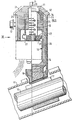
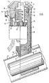
- the body parts collectively define a line of movement or guideway along which a bolt 16 can move relative to the body between a locking position shown in Figure 1 and a releasing position shown in Figure 3.
- On the shaft 10 of the steering column there is secured a bush 17 formed with circumferentially spaced slots into one of which a nose 18 of the bolt projects when the bolt is in the locking position.
- the key-operated mechanism of the lock includes a barrel 19 having an open slot at its front face 20 for receiving the key 12 ( Figure 3) appropriate to the lock.
- the barrel 19 is rotatable with the key throughout an angle of 120° relative to the body.
- driving means for driving the bolt from its locking position to its releasing position upon rotation of the key and barrel approximately 45° from the insertion position of the key and retaining means for retaining the bolt in its releasing position whilst the key is turned away from its insertion position.
- the driving means and retaining means are comprised by a member 22 interposed between the barrel and the rear body part 14.
- the member 22 is keyed to the barrel for rotation therewith.
- the member may be integral with the barrel.
- the member 22 is engaged with both the rear body part 14 and the barrel 19 so that rearward movement of the member 22 and barrel is prevented by the rear body part. Forward movement of the barrel is prevented by engagement between a flange of the barrel and the front body part 13.
- the bolt 16 includes a sleeve portion 24 which embraces a middle part of the barrel 19 and is integral with a connecting portion 25 of the bolt which is offset to one side of the longitudinal axis of the barrel.
- the nose 18 of the bolt is a structurally separate part carried -by the connecting portion 25.
- the member 25 projects outwardly beyond the periphery of the barrel 19 to present towards the front of the lock a flat part-annular face 23 which constitutes the retaining means.
- An element 26 is secured to the sleeve portion 24 of the bolt so as to move with the bolt between the locking and releasing positions.
- the element 26 is an elongate leaf spring, one end of which is embedded in the sleeve portion 24 of the bolt. The opposite end is bent back on itself to facilitate contact in abutment and sliding with the face 23.
- the spring 26 extends generally parallel to the longitudinal axis of the barrel and the line of movement of the bolt, and in this way can be readily accommodated within the compass of the lock without the need for increase in diameter. Although the bent-back end portion of the spring 26 can be deflected laterally it normally lies, even when contacting the face 23, close to the barrel 19.
- An aperture 27 opens through the member 22 from the face 23.
- the aperture 27 is sufficiently large to accommodate the bent-back end of the leaf spring 26, and the spring 26 is aligned with the aperture when the barrel 19 is turned back to the key-insertion position, ready for entry into the aperture upon withdrawal of the key.
- the sides of the aperture are inclined at an acute angle to a radius of the barrel, so that while the end portion of the spring is disposed in the aperture, rotation of the barrel can be made against the resilience of the spring to drive the bent-back end out of the aperture onto a peripheral face of the member.
- the driving means of the member 22 is a cam 28 which co-operates with a cam surface 29 ( Figure 4) on the sleeve portion 24 of the bolt for withdrawing the bolt from the locking position to the releasing position against the action of a spring 30 ( Figure 2) located between the bolt and the front body part 13.
- a cam surface 29 Figure 4
- Rotation of the barrel through 60° following insertion and turning of the key from its insertion position causes the cam surface 29 to ride up the cam 28 so as to lift the bolt fully to its releasing position and draw the spring 26 from engagement with the peripheral face of the member 22 into engagement with the face 23.
- Abutment of the spring 26 with the face 23 precludes return of the bolt to the locking position until the key has been turned back to its insertion position so as thereby to bring the spring 26 into alignment once again with the aperture 27.
- the bolt continues to be held in its releasing position when the key has been turned back to its insertion position and until the key is withdrawn, by a key-detecting element in the form of a slider 31.
- the slider is mounted in a slot which extends laterally into the barrel 19 from the key-receiving slot.
- the length of the slider is such that when it does not obstruct the key-receiving slot it projects radially from the barrel into the path of an abutment 32 on the bolt 16.
- the abutment is in the form of a pawl which can rock relative to the bolt about a transverse pivot 33.
- a leaf spring 34 is provided for urging the free end of the pawl towards the barrel 19.
- the leaf spring may also, as in this case, retain the pawl in assembled relation with the bolt.
- the pawl 32 lies to the rear of the slider 31 and does not impede radially outward movement of the slider so that the slider is free to move out of the key-receiving slot either before or during insertion of the key.
- end portions of tumblers 35 project from the barrel 19 into recesses formed in the sleeve portion 24 of the bolt and thereby constrain the barrel against rotation. Insertion of the proper key into the barrel withdraws the tumblers from the bolt and so frees the barrel for rotation. It will be understood that the slider 31 moves with the barrel and so does not obstruct movement of the pawl 32 and bolt into the releasing position.
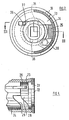
- the bolt will move completely into the locking position illustrated in Figure 1. If the nose is not completely aligned with a slot in the bush, the nose will come to rest against the periphery of the bush as shown in Figure 5 and the bolt will be held in an intermediate position between the locking and releasing positions. With the bolt in its intermediate position, the pawl 32 lies in the path of the slider 31 and will hold the slider in the key-receiving slot until an attempt is made to insert the key once more. Such insertion is possible only because the pawl 32 is able in this position to rock away from the barrel and so permit the slider to move out of the key-receiving slot, as shown in Figure 5. Once the barrel is rotated, the slider moves angularly away from the pawl and the pawl returns under the action of its spring 34 to its normal position illustrated in Figure 1.
- the multi-position electrical switch of the lock is represented, in chain-dotted outline 37, in Figure 1 only of the drawings.
- the switch is mounted within the lock housing and is coupled to the barrel 19 so as to be switched stepwise from one to the other of its four ON-settings with rotation of the barrel 19 by the key through the full 120° of rotation.
- a plunger 38 ( Figure 2) which normally projects from the lock body into an aperture in the housing.
- the plunger can be moved radially inwards so as to withdraw from the aperture in the housing only when the bolt 16 is in the releasing position.
- the sleeve portion 24 of the bolt obstructs the radially inward movement of the plunger.
- a recess (not shown) in the sleeve portion is moved into alignment with the plunger when the bolt is moved into the releasing position so as thereby to allow removal of the lock in this position only.
- the leaf spring 26 is formed of steel.
- the member 22 is formed of a relatively soft material, for example a zinc-based die casting alloy; excessive wear of the member 22 may be caused during the working life of the lock by the leaf spring.
- the element 26 may be formed partly or entirely of a material other than spring steel. Such other material would engage the member 22 and would be selected to reduce wear of this member.
- the element 26 is formed of a zinc-based die casting alloy, is of elongate form and is so arranged that an end adjacent to the member 22 can undergo limited movement towards and away from the axis of rotation of the barrel 19, the element rocking on a fulcrum at the other end of the element about an axis transverse to the axis of rotation of the barrel.
- a leaf spring which urges the element towards the axis of rotation of the barrel.
- the arrangement is similar to that of the pawl 32 and leaf spring 34.
Landscapes
- Engineering & Computer Science (AREA)
- Mechanical Engineering (AREA)
- Lock And Its Accessories (AREA)
Claims (9)
Applications Claiming Priority (2)
| Application Number | Priority Date | Filing Date | Title |
|---|---|---|---|
| GB915678 | 1978-03-08 | ||
| GB915678 | 1978-03-08 |
Publications (2)
| Publication Number | Publication Date |
|---|---|
| EP0003994A1 EP0003994A1 (fr) | 1979-09-19 |
| EP0003994B1 true EP0003994B1 (fr) | 1981-10-21 |
Family
ID=9866488
Family Applications (1)
| Application Number | Title | Priority Date | Filing Date |
|---|---|---|---|
| EP19790100509 Expired EP0003994B1 (fr) | 1978-03-08 | 1979-02-21 | Serrure, en particulier pour une colonne de direction de véhicule |
Country Status (3)
| Country | Link |
|---|---|
| EP (1) | EP0003994B1 (fr) |
| DE (1) | DE2961043D1 (fr) |
| ES (1) | ES478390A1 (fr) |
Families Citing this family (4)
| Publication number | Priority date | Publication date | Assignee | Title |
|---|---|---|---|---|
| DE3508160C1 (de) * | 1985-03-07 | 1986-06-26 | Tibbe KG, 8065 Erdweg | Lenkschloß für Kraftfahrzeuge |
| FR2783218B1 (fr) * | 1998-09-16 | 2000-10-13 | Antivols Simplex Sa | Antivol de vehicule automobile comportant des moyens perfectionnes de fixation d'un mecanisme d'antivol |
| FR2799426B1 (fr) * | 1999-09-17 | 2001-12-07 | Valeo Securite Habitacle | Antivol de direction de vehicule automobile |
| EP2692592A1 (fr) * | 2012-08-03 | 2014-02-05 | Valeo Securité Habitacle | Dispositif antivol et module de dispositif antivol pour colonne de direction d'un véhicule automobile |
Family Cites Families (6)
| Publication number | Priority date | Publication date | Assignee | Title |
|---|---|---|---|---|
| DE7044466U (de) * | Huelsbeck & Fuerst | Lenkschloß fur Kraftfahrzeuge | ||
| FR83807E (fr) * | 1964-11-24 | 1965-02-10 | Antivol notamment pour véhicules | |
| AU442857B2 (en) * | 1970-06-29 | 1970-11-20 | Josef Voss Kg | Improvements in or relating to vehicle steering column locking apparatus |
| FR2102611A5 (fr) * | 1970-08-04 | 1972-04-07 | Juy Lucien | |
| AR197559A1 (es) * | 1971-03-31 | 1974-04-23 | Cema Ind Sa | Dispositivo de traba perfecionado, aplicable a las llaves de contacto de automotores |
| IT958822B (it) * | 1972-05-09 | 1973-10-30 | Arman D Sas | Perfezionamento relativo ai disposi tivi anti furto blocca sterzo per autoveicoli comportanti un inter ruttore elettrico |
-
1979
- 1979-02-21 EP EP19790100509 patent/EP0003994B1/fr not_active Expired
- 1979-02-21 DE DE7979100509T patent/DE2961043D1/de not_active Expired
- 1979-03-07 ES ES478390A patent/ES478390A1/es not_active Expired
Also Published As
| Publication number | Publication date |
|---|---|
| DE2961043D1 (en) | 1981-12-24 |
| EP0003994A1 (fr) | 1979-09-19 |
| ES478390A1 (es) | 1980-01-01 |
Similar Documents
| Publication | Publication Date | Title |
|---|---|---|
| US3959996A (en) | Anti-theft device for automobile vehicles | |
| US6354117B1 (en) | Steering column anti-theft device for motor vehicle | |
| US5632167A (en) | Steering look apparatus | |
| US6327882B1 (en) | Motor vehicle theft-deterrent steering lock | |
| US5732580A (en) | Axially disengageable lock for a motor vehicle locking system | |
| GB2257676A (en) | Vehicle steering lock | |
| US3863473A (en) | Cylinder lock with key in particular for steering-wheel locks for motor vehicles | |
| JP3527394B2 (ja) | ステアリングロック装置 | |
| GB1584063A (en) | Anti-theft locking device | |
| US5315851A (en) | Steering lock device for vehicle | |
| GB2114646A (en) | Steering lock for motor vehicles | |
| EP0003994B1 (fr) | Serrure, en particulier pour une colonne de direction de véhicule | |
| EP0336219A2 (fr) | Dispositif de verrouillage de direction | |
| CN101595015A (zh) | 用于车辆的防盗安全装置 | |
| US4248070A (en) | Steering column and ignition lock for motor vehicle | |
| CN101890933B (zh) | 用于机动车无钥匙启动系统的机械点火锁 | |
| GB2024924A (en) | Steering column locks | |
| EP0636523A1 (fr) | Dispositif d'anti-vol de direction | |
| GB1296972A (fr) | ||
| US5457973A (en) | Axially activated system for a key lock | |
| JP4190902B2 (ja) | ステアリングロック装置 | |
| GB2298229A (en) | A lock | |
| JP2009051261A (ja) | ステアリングロック装置 | |
| JPH04134773U (ja) | ステアリングロツク装置 | |
| JP3002372B2 (ja) | ステアリングロック装置 |
Legal Events
| Date | Code | Title | Description |
|---|---|---|---|
| PUAI | Public reference made under article 153(3) epc to a published international application that has entered the european phase |
Free format text: ORIGINAL CODE: 0009012 |
|
| AK | Designated contracting states |
Designated state(s): DE FR GB |
|
| 17P | Request for examination filed | ||
| DET | De: translation of patent claims | ||
| GRAA | (expected) grant |
Free format text: ORIGINAL CODE: 0009210 |
|
| AK | Designated contracting states |
Designated state(s): DE FR GB |
|
| REF | Corresponds to: |
Ref document number: 2961043 Country of ref document: DE Date of ref document: 19811224 |
|
| PGFP | Annual fee paid to national office [announced via postgrant information from national office to epo] |
Ref country code: FR Payment date: 19890209 Year of fee payment: 11 |
|
| PGFP | Annual fee paid to national office [announced via postgrant information from national office to epo] |
Ref country code: GB Payment date: 19890228 Year of fee payment: 11 |
|
| PGFP | Annual fee paid to national office [announced via postgrant information from national office to epo] |
Ref country code: DE Payment date: 19890323 Year of fee payment: 11 |
|
| PG25 | Lapsed in a contracting state [announced via postgrant information from national office to epo] |
Ref country code: GB Effective date: 19900221 |
|
| GBPC | Gb: european patent ceased through non-payment of renewal fee | ||
| PG25 | Lapsed in a contracting state [announced via postgrant information from national office to epo] |
Ref country code: FR Effective date: 19901031 |
|
| PG25 | Lapsed in a contracting state [announced via postgrant information from national office to epo] |
Ref country code: DE Effective date: 19901101 |
|
| REG | Reference to a national code |
Ref country code: FR Ref legal event code: ST |
|
| PLBE | No opposition filed within time limit |
Free format text: ORIGINAL CODE: 0009261 |
|
| STAA | Information on the status of an ep patent application or granted ep patent |
Free format text: STATUS: NO OPPOSITION FILED WITHIN TIME LIMIT |