EP0004120A2 - Machine à engrenages avec des moyens de décompression du liquide dans l'espace entredents - Google Patents
Machine à engrenages avec des moyens de décompression du liquide dans l'espace entredents Download PDFInfo
- Publication number
- EP0004120A2 EP0004120A2 EP79200119A EP79200119A EP0004120A2 EP 0004120 A2 EP0004120 A2 EP 0004120A2 EP 79200119 A EP79200119 A EP 79200119A EP 79200119 A EP79200119 A EP 79200119A EP 0004120 A2 EP0004120 A2 EP 0004120A2
- Authority
- EP
- European Patent Office
- Prior art keywords
- recesses
- face
- pressure chamber
- suction chamber
- helical
- Prior art date
- Legal status (The legal status is an assumption and is not a legal conclusion. Google has not performed a legal analysis and makes no representation as to the accuracy of the status listed.)
- Granted
Links
Images



Classifications
-
- F—MECHANICAL ENGINEERING; LIGHTING; HEATING; WEAPONS; BLASTING
- F04—POSITIVE - DISPLACEMENT MACHINES FOR LIQUIDS; PUMPS FOR LIQUIDS OR ELASTIC FLUIDS
- F04C—ROTARY-PISTON, OR OSCILLATING-PISTON, POSITIVE-DISPLACEMENT MACHINES FOR LIQUIDS; ROTARY-PISTON, OR OSCILLATING-PISTON, POSITIVE-DISPLACEMENT PUMPS
- F04C2/00—Rotary-piston machines or pumps
- F04C2/08—Rotary-piston machines or pumps of intermeshing-engagement type, i.e. with engagement of co-operating members similar to that of toothed gearing
- F04C2/082—Details specially related to intermeshing engagement type machines or pumps
- F04C2/088—Elements in the toothed wheels or the carter for relieving the pressure of fluid imprisoned in the zones of engagement
Definitions
- the invention relates to a gear machine (pump or motor) with helical gears meshing in external or internal engagement, the shafts of which are rotatably mounted in the housing and / or housing cover or in bearing bodies arranged in the housing, the engagement area on the side surfaces facing the gearwheels, i.e. in the Housing wall and / or housing cover or in the bearing bodies, recesses are formed, of which the recesses on the pressure chamber side are connected to the pressure chamber and the recesses on the suction chamber side are connected to the suction chamber.
- the recess on the pressure chamber side and the suction chamber side in a side surface facing the gearwheels are separated from one another by a web of a certain width.
- a backlash of zero or almost zero is aimed for in order to achieve a greatly reduced flow rate fluctuation and torque fluctuation.
- Zero or almost zero means an backlash that is less than the usual backlash of e.g. Is 0.3 mm. This is achieved in that in the case of this straight toothing without or almost without backlash, the web width between the recess on the pressure chamber side and on the suction chamber side is reduced to half the value - compared to that of the same toothing with backlash. The problem of squeezing the hydraulic fluid and cavitation in an enclosed tooth gap occurs even more than in the case of a gear machine with backlash.
- the invention has for its object to provide a gear machine of the type mentioned, in which the available squeezing areas are so large are that the hydraulic fluid can flow into the pinch oil chamber without squeezing or danger of cavitation and can flow out of it again.
- the pressure chamber side and the suction chamber side recess on the leading end face of the helical toothing are thus offset by a distance V in the suction chamber side compared to the pressure chamber side and the suction chamber side recess on the trailing end side of the helical toothing.
- the web width is unchanged from that of the comparable spur toothing of the same face cut.
- the size of the displacement of the recesses is independent of whether there is backlash or not.
- the technical progress achievable with the invention is based on several advantages.
- the available squeezing surfaces of the recesses are significantly larger compared to the comparable straight toothing and can also flow into the pinch oil space and also flow out of it again via the.
- the displacement process can take place undisturbed, the theoretical flow fluctuation is minimal and the pressure fluid can flow in or out of the enclosed tooth space undisturbed without the risk of crushing or cavitation.
- the gear machine has a very low sound pressure level with little technical effort, i.e. compared to a known gear machine, the same flow rate can be achieved in the gear machine according to the invention at the same sound pressure level, the speed should be higher and the stroke volume smaller.
- the gear machine according to FIGS. 1 to 3 has a housing 1 which is closed on both sides by housing covers 2 and 3.
- the housing 1 has a continuous housing opening 4, which is formed by two intersecting bores 5 and 6.
- the housing opening 4 has approximately the shape of an eight.
- two bearing bodies 7 and 8 are arranged, in the bearing bores 9 and 10 of which a driving gear 11 is rotatably mounted.
- two bearing bodies 12 and 13 are arranged in the bore 6, in whose bearing bores 14 and 15 the driven gear wheel 16 is rotatably mounted.
- the gear machine according to Fig. La consists of a housing la with only one housing cover 2a.
- the gears 11 and 16 are rotatably supported with their shafts directly in the housing la or in the housing cover 2a.
- the driving gear 11 has right-hand teeth; the driven gear 16 has left-rising teeth.
- the driving gear 11 is driven clockwise.
- Fluctuation recesses 19, 20, 21, 22 attached so that when the volume of the enclosed tooth gap decreases, the enclosed tooth gap is connected to the pressure chamber D via the recesses 19 and 21 displaced by a distance V from one another, and that with increasing volume of the enclosed tooth gap the enclosed tooth gap is connected to the suction space S via the recesses 20 and 22 on the suction space side which are displaced by a distance V from one another.
- Fig. 4 it is indicated for a helical toothing with backlash, how the recesses 19 to 22 are designed;
- the center distance extends from the center M 1 of the driving helical gear 11 with right-hand teeth to the center M 2 of the driven helical gear 16 with left-hand teeth.
- the pole P lies on the middle of the connecting line from M 1 to M 2.
- the thin solid line 23 follows the contours of the toothing at the front trailing end Face 18 of the helical toothing.
- the thin dash-dotted line 24 follows the contour of the toothing on the rear leading end face 17 of the helical toothing.
- the thick line 25 represents the contour of the helical toothing in the center of the wheel.
- the helical toothing is drawn for the position in which the enclosed tooth gap reaches its smallest volume or in which the hatched area of the enclosed tooth gap 26 reaches its minimum in the wheel center.
- the pressure changeover process takes place at this very moment, ie the tooth gap is separated from the pressure chamber D and connected to the suction chamber S.
- the recesses of the helical toothing with backlash are matched to this pressure changeover process.
- the straight web edges 27 and 28 of the essentially rectangular recesses 19 and 20 of lines running parallel to M 1 , M 2 are at the rear leading end face 17 of the helical toothing through the two contact points 30 lying in this rear leading end face 17 on the engagement plane 29 and 31 formed.
- the straight web edges 32 and 33 of the substantially rectangular recesses 21 and 22 of lines running parallel to M 1 , M 2 are through the two contact points 34 located in this front trailing end face 18 on the engagement plane 29 and 35 formed.
- the line of symmetry 88 to the web edges 27, 28 is in the direction of the suction space S by a distance Y and the line of symmetry 89 to the Web edges 32, 33 is in the direction of pressure chamber D by a distance offset to the connecting line M 1 M 2 .
- the recesses 19, 2 1 and 2 0 , 22 shifted by the distance V can be seen from FIG. 3.
- the depth 36 of the recesses 19 to 22 is a few millimeters and the width 37 of the recesses 19 to 22 is approximately equal to the tooth height.
- the recesses 19, 20 and 21, 22 on the pressure chamber side and suction chamber side, respectively, located on one end face of the toothing, are separated from one another by a web with the width 38.
- the web width 38 is, compared to the web width 39 of the comparable straight toothing shown in FIG. 5 with the same face cut, unchanged.
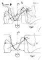
- the squeezing surfaces of the straight toothing available for a torsion angle ⁇ 1 are shown in FIG. 5 and the squeezing surfaces of the helical toothing available in FIG. 6.
- the squeezing surface 40 is available on both end faces of the straight toothing.
- the squeezing surface 41 is available on the leading end face 17 and the squeezing surface 42 is available on the trailing end face 18.
- a squeezing surface with a gap 43 is available.
- the recesses 19 to 22 on the two end faces 17, 18 of the helical toothing can also have a somewhat different shape.
- the recesses must always be designed such that the enclosed tooth gap is connected to the pressure chamber D via the recesses 19, 21 on the pressure chamber side only with decreasing size of the area of the enclosed tooth gap in the wheel center and that only with increasing size of the area of the enclosed tooth gap in the wheel center the enclosed tooth gap is connected to the suction space S via the recesses 20, 22 on the suction space side.
- notches 44, 45, 46, 47 are made, which are defined by the root circle 48, 49 and the root circle contour 50, 51, 52, 53 Tooth flank of the adjacent gearwheel is formed at an angle of rotation ⁇ 1 , at which the area of the enclosed tooth gap in the wheel center reaches its minimum.
- the notches 44 to 47 according to the invention enlarge the available squeezing area even more.
- the web width 77 is equal to the web width 54 of the comparable straight toothing without or almost without backlash, as can be seen from FIGS. 8 and 9.
- the recesses are designed such that, with the volume of an enclosed tooth gap decreasing, the enclosed tooth gap via the recesses 55 and 56 with the pressure chamber D displaced by a distance V from one another is connected, and that as the volume of the enclosed tooth gap increases, the enclosed tooth gap is connected to the suction chamber S via the recesses 57 and 58 on the suction chamber side displaced by a distance V from one another.
- the size of the area of the enclosed tooth gap in the center of the wheel becomes smaller and with increasing Volume of this enclosed tooth gap 59 the size of the area of the enclosed tooth gap 59 becomes larger in the center of the wheel, can be determined in the same way as for the helical toothing with backlash, for which angle of rotation 9 1 of the driving gear 11 this enclosed tooth gap reaches its smallest volume and when so the pressure reversal process must take place.
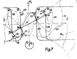
- FIG. 9 for a helical toothing with the same face cut as the helical toothing according to FIG. 4, but without or almost without backlash, it is indicated how the recesses 55, 56, 57, 58 according to the invention are designed.
- the thin solid line 60 follows the contours of the helical teeth on the front trailing face 61 of the helical teeth.
- the thin dash-dotted line 62 follows the contours of the helical teeth on the rear leading end face 63 of the helical teeth.
- the thick line 64 represents the contour of the helical toothing in the center of the wheel.
- the helical toothing is drawn in the position in which an enclosed tooth gap reaches its smallest volume or in which the hatched area of the enclosed tooth gap 59 is smallest in the center of the wheel. At this very moment, the pressure changeover process must take place, ie the tooth gap is separated from the pressure chamber D and with Suction chamber S connected.
- the recesses 55 to 58 of the helical toothing are matched to this pressure reversing process with no or almost no backlash.
- the straight web edges 65 and 66 of the substantially rectangular recesses 56 and 58 of lines running parallel to M 1 M 2 on the rear leading end face 63 of the helical toothing become through the contact points 69 lying in this rear leading end face 63 on the engagement planes 68 and 67 or 70 formed.
- the helical teeth are to the front trailing end face 61, the straight web edges 71 and 72 of substantially rectangular recesses 55 and 57 of paral- lel extending to M 1 M 2 lines by two in the front trailing end face 61 on the engagement planes 63 and 67 lying contact points 73 and 74 are formed.
- the line of symmetry 90 to the web edges 65, 66 is in the direction of the suction space S by the distance and the line of symmetry 91 to the web edges 71, 72 is in the direction of the pressure space D by the same distance offset to the connecting line M 1 M 2 .
- the depth 75 of the recesses 55 to 58 is a few millimeters.
- the 3reide 76 of the recesses 55 to 58 is approximately equal to the tooth height.
- the recesses 55, 58 and 55, 57 on the pressure chamber side and suction chamber side, respectively, located on the front face of the helical toothing, are separated from one another by a web with the width 77.
- the land width 77 is compared with the land width 54 the manner shown in Fig. 8 ver G leichbaren Geradverzahnurg without or almost without any backlash with the same transverse section remained unchanged.
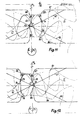
- notches 78, 79, 80, 81, 82, 83, 84, 85 are made by the root circles 86, 87 and contours of the tooth flank of the adjacent gearwheel are formed at an angle of rotation ⁇ 1 at which the area of an enclosed M 1 or M 2 side tooth gap in the wheel center reaches its minimum.
- These notches 78 to 85 increase the available squeezing area even more.
- 11 and 12 show the construction of the notches 79, 81, 82 84 only for the angle of rotation ⁇ 1 , at which the area of the enclosed M 2 -side tooth space is at its minimum in the middle.
Landscapes
- Engineering & Computer Science (AREA)
- Mechanical Engineering (AREA)
- General Engineering & Computer Science (AREA)
- Rotary Pumps (AREA)
- Gears, Cams (AREA)
Applications Claiming Priority (2)
| Application Number | Priority Date | Filing Date | Title |
|---|---|---|---|
| DE2810563A DE2810563C2 (de) | 1978-03-10 | 1978-03-10 | Zahnradmaschine (Pumpe oder Motor) |
| DE2810563 | 1978-03-10 |
Publications (3)
| Publication Number | Publication Date |
|---|---|
| EP0004120A2 true EP0004120A2 (fr) | 1979-09-19 |
| EP0004120A3 EP0004120A3 (en) | 1979-10-03 |
| EP0004120B1 EP0004120B1 (fr) | 1983-04-06 |
Family
ID=6034123
Family Applications (1)
| Application Number | Title | Priority Date | Filing Date |
|---|---|---|---|
| EP79200119A Expired EP0004120B1 (fr) | 1978-03-10 | 1979-03-09 | Machine à engrenages avec des moyens de décompression du liquide dans l'espace entredents |
Country Status (3)
| Country | Link |
|---|---|
| US (1) | US4290739A (fr) |
| EP (1) | EP0004120B1 (fr) |
| DE (1) | DE2810563C2 (fr) |
Cited By (2)
| Publication number | Priority date | Publication date | Assignee | Title |
|---|---|---|---|---|
| GB2313627A (en) * | 1996-05-29 | 1997-12-03 | Roy William Masters | Rotary engine |
| DE102020100241A1 (de) | 2020-01-08 | 2021-07-08 | Thyssenkrupp Ag | Verfahren zur Herstellung von Phosphorsäure und Klinkerprozess-geeigneter Kalziumsulfatqualität zur kommerziellen und industriellen Verwertung von Kalziumsulfat |
Families Citing this family (30)
| Publication number | Priority date | Publication date | Assignee | Title |
|---|---|---|---|---|
| JPS59501514A (ja) * | 1982-09-07 | 1984-08-23 | フオ−ド モ−タ− カンパニ− | はすば歯車ポンプ |
| US4824331A (en) * | 1987-07-29 | 1989-04-25 | Hydreco, Incorporated | Variable discharge gear pump with energy recovery |
| DE4040409C1 (fr) * | 1990-12-18 | 1992-05-14 | Vse Schweisstechnik Gmbh, 5982 Neuenrade, De | |
| US5131829A (en) * | 1991-06-19 | 1992-07-21 | Eaton Corporation | Trapped volume vent means for meshing lobes of roots-type supercharger |
| US5733111A (en) * | 1996-12-02 | 1998-03-31 | Ford Global Technologies, Inc. | Gerotor pump having inlet and outlet relief ports |
| US5865239A (en) * | 1997-02-05 | 1999-02-02 | Micropump, Inc. | Method for making herringbone gears |
| US6544008B1 (en) * | 1997-07-18 | 2003-04-08 | John K. Apostolides | Internal vent for reducing seal pressure in prelubrication pump assembly |
| US6708710B1 (en) * | 1997-10-30 | 2004-03-23 | Rpm Industries, Inc. | Vehicle fluid change apparatus and method |
| US6988506B1 (en) | 1997-10-30 | 2006-01-24 | Rpm Industries, Inc. | Fluid transfer system |
| US9062575B2 (en) * | 1997-10-30 | 2015-06-23 | RPM Industries, LLC | Methods and systems for performing, monitoring and analyzing multiple machine fluid processes |
| US7150286B2 (en) * | 1997-10-30 | 2006-12-19 | Rpm Industries, Inc. | Methods and systems for performing, monitoring and analyzing multiple machine fluid processes |
| US6042352A (en) * | 1998-08-12 | 2000-03-28 | Argo-Tech Corporation | Bearing with pulsed bleed configuration |
| JP3830313B2 (ja) * | 1999-09-06 | 2006-10-04 | 株式会社ジェイテクト | ギヤポンプ |
| US6853954B2 (en) | 2002-09-24 | 2005-02-08 | John K. Apostolides | Methods and systems for collecting and processing data in association with machine operation and maintenance |
| WO2006090495A1 (fr) * | 2005-02-24 | 2006-08-31 | Shimadzu Corporation | Pompe a engrenage |
| US20070201989A1 (en) * | 2005-10-14 | 2007-08-30 | Parker-Hannifin | Low ripple gear pump/motor |
| US20070178003A1 (en) * | 2005-11-22 | 2007-08-02 | Parker-Hannifin Corporation | Gear pump with ripple chamber for low noise and pressure ripples |
| US20080063554A1 (en) * | 2006-09-08 | 2008-03-13 | Gifford Thomas K | Precision flow gear pump |
| US20090089168A1 (en) * | 2007-01-10 | 2009-04-02 | Phyllis Adele Schneck | ACE (Alternative Currency Exchange): Alternative Currency Tracking and Mapping System and Method |
| ITBO20070172A1 (it) * | 2007-03-14 | 2008-09-15 | Mario Antonio Morselli | Apparecchiatura idraulica ad ingranaggi perfezionata |
| US7878781B2 (en) * | 2007-12-11 | 2011-02-01 | Hamilton Sundstrand Corporation | Gear pump cavitation reduction |
| US8911222B2 (en) | 2011-02-25 | 2014-12-16 | Hamilton Sundstrand Corporation | Input shaft assembly for gear pump |
| US8814547B2 (en) | 2011-02-25 | 2014-08-26 | Hamilton Sundstrand Corporation | Seal retaining sleeve for gear pump |
| US8801410B2 (en) | 2011-02-25 | 2014-08-12 | Hamilton Sundstrand Corporation | Coupling shaft for gear pump |
| US8992192B2 (en) | 2011-02-25 | 2015-03-31 | Hamilton Sundstrand Corporation | Input shaft lubrication for gear pump |
| US9677559B2 (en) | 2011-02-25 | 2017-06-13 | Hamilton Sundstrand Corporation | Bearing face geometry for gear pump |
| US9303644B2 (en) | 2013-11-26 | 2016-04-05 | Woodward, Inc. | Gear pump bearing dam |
| DE102015201961A1 (de) | 2015-02-04 | 2016-08-04 | Volkswagen Aktiengesellschaft | Verfahren zum Betrieb einer Verdrängerpumpe sowie eine hierfür bestimmte Verdrängerpumpe |
| US10563653B2 (en) | 2016-01-12 | 2020-02-18 | Hamilton Sundstrand Corporation | Gear pump |
| US10443597B2 (en) | 2016-01-12 | 2019-10-15 | Hamilton Sundstrand Corporation | Gears and gear pumps |
Family Cites Families (15)
| Publication number | Priority date | Publication date | Assignee | Title |
|---|---|---|---|---|
| US1634023A (en) * | 1927-06-28 | Ptjmp | ||
| US1129090A (en) * | 1914-04-08 | 1915-02-23 | American La France Fire Engine Company Inc | Gear-pump. |
| US1233069A (en) * | 1916-05-22 | 1917-07-10 | Leonard Pump And Motor Co | Pump and liquids. |
| US1706829A (en) * | 1928-05-28 | 1929-03-26 | Joseph Mercadante | Pump |
| US2147405A (en) * | 1935-01-05 | 1939-02-14 | Trico Products Corp | Motor vehicle power plant |
| US2136142A (en) * | 1935-06-25 | 1938-11-08 | American Viscose Corp | Rayon-spinning pump |
| US2338065A (en) * | 1940-06-13 | 1943-12-28 | Joseph F Keller | Gear pump |
| US2354992A (en) * | 1941-11-11 | 1944-08-01 | Westinghouse Electric & Mfg Co | Gear pump |
| US2781730A (en) * | 1952-10-22 | 1957-02-19 | Thompson Prod Inc | Implement pump |
| US2884864A (en) * | 1955-04-14 | 1959-05-05 | Borg Warner | Pressure loaded pump, trapping grooves |
| CH399193A (de) * | 1960-08-18 | 1966-03-31 | Reiners & Wiggermann | Verstell-Zahnradpumpe |
| FR1355756A (fr) * | 1963-02-07 | 1964-03-20 | Johannes Freres | Pompe à engrenage perfectionnée destinée plus particulièrement aux engins de travaux publics |
| DE2249952C3 (de) * | 1972-10-12 | 1975-03-27 | Zahnradfabrik Friedrichshafen Ag, 7990 Friedrichshafen | Hydraulische Zahnradmaschine |
| DE2623357A1 (de) * | 1976-05-25 | 1977-12-15 | Bosch Gmbh Robert | Zahnradmaschine (pumpe oder motor) |
| DE2701303C3 (de) * | 1977-01-14 | 1983-02-17 | Zahnradfabrik Friedrichshafen Ag, 7990 Friedrichshafen | Hydraulische Zahnradmaschine |
-
1978
- 1978-03-10 DE DE2810563A patent/DE2810563C2/de not_active Expired
-
1979
- 1979-03-08 US US06/018,718 patent/US4290739A/en not_active Expired - Lifetime
- 1979-03-09 EP EP79200119A patent/EP0004120B1/fr not_active Expired
Cited By (3)
| Publication number | Priority date | Publication date | Assignee | Title |
|---|---|---|---|---|
| GB2313627A (en) * | 1996-05-29 | 1997-12-03 | Roy William Masters | Rotary engine |
| DE102020100241A1 (de) | 2020-01-08 | 2021-07-08 | Thyssenkrupp Ag | Verfahren zur Herstellung von Phosphorsäure und Klinkerprozess-geeigneter Kalziumsulfatqualität zur kommerziellen und industriellen Verwertung von Kalziumsulfat |
| WO2021140074A1 (fr) | 2020-01-08 | 2021-07-15 | Thyssenkrupp Industrial Solutions Ag | Procédé de production d'acide phosphorique et de sulfate de calcium de qualité appropriée pour un procédé de clinker en vue d'une utilisation commerciale et industrielle de sulfate de calcium |
Also Published As
| Publication number | Publication date |
|---|---|
| DE2810563C2 (de) | 1982-10-28 |
| DE2810563A1 (de) | 1979-09-13 |
| US4290739A (en) | 1981-09-22 |
| EP0004120B1 (fr) | 1983-04-06 |
| EP0004120A3 (en) | 1979-10-03 |
Similar Documents
| Publication | Publication Date | Title |
|---|---|---|
| EP0004120B1 (fr) | Machine à engrenages avec des moyens de décompression du liquide dans l'espace entredents | |
| EP0994257B1 (fr) | Pompe à engrenages externes avec limitation du débit | |
| DE2554105C2 (de) | Zahnradmaschine (Pumpe oder Motor) | |
| DE19613833A1 (de) | Innenzahnradmaschine, insbesondere Innenzahnradpumpe | |
| DE2318753C2 (de) | Zahnradmaschine | |
| DE3249585C2 (de) | Zahnradpumpe f}r inkompressible Medien | |
| DE2510496C3 (de) | Zahnradmaschine (Pumpe oder Motor) | |
| DE2926566A1 (de) | Stroemungsmesser mit positiver verdraengung | |
| DE1806149A1 (de) | Dichtung an Zahnradpumpen | |
| DE69513142T2 (de) | Innenzahnradpumpe mit radialen Zuführungsröhren | |
| DE2848994A1 (de) | Zahnradmaschine (pumpe oder hydromotor) | |
| DE1403935A1 (de) | Zahnradpumpe oder Zahnradmotor | |
| DE2024339C2 (de) | Zahnradverdrängermaschine für Flüssigkeiten, insbesondere Zahnradpumpe | |
| EP0004119A2 (fr) | Machine à engrenages avec des roues dentées décalées l'une par rapport à l'autre en direction circonférentielle | |
| DE2249952A1 (de) | Zahnradmaschine | |
| DE2456387C2 (de) | Dosiervorrichtung | |
| WO2001002730A1 (fr) | Machine a engrenage interne destinee au fonctionnement reversible dans un circuit hydraulique ferme | |
| DE2517455A1 (de) | Zahnradmaschine (pumpe oder motor) | |
| DE2414760A1 (de) | Zahnradpumpe | |
| CH657434A5 (en) | Rolling-contact mechanism and the use of the latter | |
| EP2690252A1 (fr) | Trochoid internal gear machine | |
| EP0189560B1 (fr) | Machine à engrenage (pompe ou moteur) | |
| DE2701303C3 (de) | Hydraulische Zahnradmaschine | |
| DE2306065C3 (de) | Zahnradpumpe oder -Motor mit im Außeneingriff stehenden Zahnrädern | |
| DE2709913C2 (de) | Zahnradpumpe |
Legal Events
| Date | Code | Title | Description |
|---|---|---|---|
| PUAI | Public reference made under article 153(3) epc to a published international application that has entered the european phase |
Free format text: ORIGINAL CODE: 0009012 |
|
| PUAL | Search report despatched |
Free format text: ORIGINAL CODE: 0009013 |
|
| AK | Designated contracting states |
Designated state(s): CH FR GB IT NL SE |
|
| AK | Designated contracting states |
Designated state(s): CH FR GB IT NL SE |
|
| 17P | Request for examination filed | ||
| RAP1 | Party data changed (applicant data changed or rights of an application transferred) |
Owner name: KORSE, THEODORUS HENRICUS |
|
| ITF | It: translation for a ep patent filed | ||
| GRAA | (expected) grant |
Free format text: ORIGINAL CODE: 0009210 |
|
| AK | Designated contracting states |
Designated state(s): CH FR GB IT NL SE |
|
| PG25 | Lapsed in a contracting state [announced via postgrant information from national office to epo] |
Ref country code: NL Effective date: 19830406 |
|
| ET | Fr: translation filed | ||
| NLV1 | Nl: lapsed or annulled due to failure to fulfill the requirements of art. 29p and 29m of the patents act | ||
| PGFP | Annual fee paid to national office [announced via postgrant information from national office to epo] |
Ref country code: CH Payment date: 19840228 Year of fee payment: 6 |
|
| PGFP | Annual fee paid to national office [announced via postgrant information from national office to epo] |
Ref country code: FR Payment date: 19840306 Year of fee payment: 6 |
|
| PGFP | Annual fee paid to national office [announced via postgrant information from national office to epo] |
Ref country code: SE Payment date: 19840331 Year of fee payment: 6 |
|
| PG25 | Lapsed in a contracting state [announced via postgrant information from national office to epo] |
Ref country code: SE Effective date: 19870310 |
|
| PG25 | Lapsed in a contracting state [announced via postgrant information from national office to epo] |
Ref country code: CH Effective date: 19870331 |
|
| GBPC | Gb: european patent ceased through non-payment of renewal fee | ||
| PG25 | Lapsed in a contracting state [announced via postgrant information from national office to epo] |
Ref country code: FR Free format text: LAPSE BECAUSE OF NON-PAYMENT OF DUE FEES Effective date: 19871130 |
|
| REG | Reference to a national code |
Ref country code: CH Ref legal event code: PL |
|
| REG | Reference to a national code |
Ref country code: FR Ref legal event code: ST |
|
| PG25 | Lapsed in a contracting state [announced via postgrant information from national office to epo] |
Ref country code: GB Effective date: 19881117 |
|
| EUG | Se: european patent has lapsed |
Ref document number: 79200119.0 Effective date: 19880215 |
|
| PLBE | No opposition filed within time limit |
Free format text: ORIGINAL CODE: 0009261 |
|
| STAA | Information on the status of an ep patent application or granted ep patent |
Free format text: STATUS: NO OPPOSITION FILED WITHIN TIME LIMIT |