EP0004179A1 - Raccord pour échafaudage tubulaire - Google Patents
Raccord pour échafaudage tubulaire Download PDFInfo
- Publication number
- EP0004179A1 EP0004179A1 EP79300339A EP79300339A EP0004179A1 EP 0004179 A1 EP0004179 A1 EP 0004179A1 EP 79300339 A EP79300339 A EP 79300339A EP 79300339 A EP79300339 A EP 79300339A EP 0004179 A1 EP0004179 A1 EP 0004179A1
- Authority
- EP
- European Patent Office
- Prior art keywords
- coupling
- ring
- peg
- body member
- standard
- Prior art date
- Legal status (The legal status is an assumption and is not a legal conclusion. Google has not performed a legal analysis and makes no representation as to the accuracy of the status listed.)
- Granted
Links
- 230000008878 coupling Effects 0.000 title claims abstract description 34
- 238000010168 coupling process Methods 0.000 title claims abstract description 34
- 238000005859 coupling reaction Methods 0.000 title claims abstract description 34
- 230000007423 decrease Effects 0.000 claims description 3
- 238000003466 welding Methods 0.000 abstract 1
- 230000008901 benefit Effects 0.000 description 2
- 239000002184 metal Substances 0.000 description 2
- 230000008439 repair process Effects 0.000 description 2
- 230000009471 action Effects 0.000 description 1
- 239000000956 alloy Substances 0.000 description 1
- 229910045601 alloy Inorganic materials 0.000 description 1
- 238000005266 casting Methods 0.000 description 1
- 238000004512 die casting Methods 0.000 description 1
- 238000005242 forging Methods 0.000 description 1
- 239000003365 glass fiber Substances 0.000 description 1
- 150000002500 ions Chemical class 0.000 description 1
- 239000000463 material Substances 0.000 description 1
- 230000004048 modification Effects 0.000 description 1
- 238000012986 modification Methods 0.000 description 1
- 239000002990 reinforced plastic Substances 0.000 description 1
- 238000005096 rolling process Methods 0.000 description 1
Images


Classifications
-
- E—FIXED CONSTRUCTIONS
- E04—BUILDING
- E04G—SCAFFOLDING; FORMS; SHUTTERING; BUILDING IMPLEMENTS OR AIDS, OR THEIR USE; HANDLING BUILDING MATERIALS ON THE SITE; REPAIRING, BREAKING-UP OR OTHER WORK ON EXISTING BUILDINGS
- E04G7/00—Connections between parts of the scaffold
- E04G7/30—Scaffolding bars or members with non-detachably fixed coupling elements
- E04G7/302—Scaffolding bars or members with non-detachably fixed coupling elements for connecting crossing or intersecting bars or members
- E04G7/306—Scaffolding bars or members with non-detachably fixed coupling elements for connecting crossing or intersecting bars or members the added coupling elements are fixed at several bars or members to connect
- E04G7/308—Scaffolding bars or members with non-detachably fixed coupling elements for connecting crossing or intersecting bars or members the added coupling elements are fixed at several bars or members to connect without tying means for connecting the bars or members
-
- E—FIXED CONSTRUCTIONS
- E04—BUILDING
- E04G—SCAFFOLDING; FORMS; SHUTTERING; BUILDING IMPLEMENTS OR AIDS, OR THEIR USE; HANDLING BUILDING MATERIALS ON THE SITE; REPAIRING, BREAKING-UP OR OTHER WORK ON EXISTING BUILDINGS
- E04G7/00—Connections between parts of the scaffold
- E04G7/02—Connections between parts of the scaffold with separate coupling elements
-
- E—FIXED CONSTRUCTIONS
- E04—BUILDING
- E04G—SCAFFOLDING; FORMS; SHUTTERING; BUILDING IMPLEMENTS OR AIDS, OR THEIR USE; HANDLING BUILDING MATERIALS ON THE SITE; REPAIRING, BREAKING-UP OR OTHER WORK ON EXISTING BUILDINGS
- E04G7/00—Connections between parts of the scaffold
- E04G7/02—Connections between parts of the scaffold with separate coupling elements
- E04G7/06—Stiff scaffolding clamps for connecting scaffold members of common shape
- E04G7/22—Stiff scaffolding clamps for connecting scaffold members of common shape for scaffold members in end-to-side relation
-
- E—FIXED CONSTRUCTIONS
- E04—BUILDING
- E04G—SCAFFOLDING; FORMS; SHUTTERING; BUILDING IMPLEMENTS OR AIDS, OR THEIR USE; HANDLING BUILDING MATERIALS ON THE SITE; REPAIRING, BREAKING-UP OR OTHER WORK ON EXISTING BUILDINGS
- E04G7/00—Connections between parts of the scaffold
- E04G7/30—Scaffolding bars or members with non-detachably fixed coupling elements
- E04G7/302—Scaffolding bars or members with non-detachably fixed coupling elements for connecting crossing or intersecting bars or members
- E04G7/306—Scaffolding bars or members with non-detachably fixed coupling elements for connecting crossing or intersecting bars or members the added coupling elements are fixed at several bars or members to connect
- E04G7/307—Scaffolding bars or members with non-detachably fixed coupling elements for connecting crossing or intersecting bars or members the added coupling elements are fixed at several bars or members to connect with tying means for connecting the bars or members
-
- Y—GENERAL TAGGING OF NEW TECHNOLOGICAL DEVELOPMENTS; GENERAL TAGGING OF CROSS-SECTIONAL TECHNOLOGIES SPANNING OVER SEVERAL SECTIONS OF THE IPC; TECHNICAL SUBJECTS COVERED BY FORMER USPC CROSS-REFERENCE ART COLLECTIONS [XRACs] AND DIGESTS
- Y10—TECHNICAL SUBJECTS COVERED BY FORMER USPC
- Y10T—TECHNICAL SUBJECTS COVERED BY FORMER US CLASSIFICATION
- Y10T403/00—Joints and connections
- Y10T403/30—Laterally related members connected by latch means, e.g., scaffold connectors
Definitions
- This invention relates to couplings for tubular scaffolding.
- a disadvantage of existing couplings for tubular scaffolding is the difficulty of overhead working when mounting the couplings on standards, and securing the ledgers and transoms thereto, particularly when they are located 6' above previous level.
- a eoupling comprising in combination, a body member for location around a standard, a wedge ring member which is co-planar and rotatably associated with the body member, and a plurality of pegs, the body member having a central aperture for receiving the standard therethrough and a plurality of radially disposed insets which combine with the wedge ring member to form apertures to receive the pegs therein parallel to the central aperture; the wedge ring member having a wedging surface for engaging the pegs when the ring member is rotated into a wedging position and for disengaging the pegs when the ring member is rotated into a disengaged position.
- said wedge ring member has a wedging surface which decreases the radial dimension of each radial aperture when the ring member is rotated into a wedging position.
- the body member is mounted on a standard by means of a pin passing through diametral apertures in the body member and standard.
- the wedge ring member has diametrically opposed slots in which the ends of the pin are located.
- said pin is a spiral pin.
- each peg comprises a shank and a head, the shank having a cross-section for location in the radial aperture and the head having a cylindrical extension extending at right angles to the shank for engaging a tubular ledger or transom.
- the longitudinal axis of the shank is off set relative to that of the head.
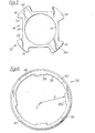
- the coupling includes a body member or boss 10 having a central cylind- rical passage 12 and four equi-spaced radially extending projections 14 which form between them four insets .16 of substantially U-shape in plan.
- the web 18 and one side 20 of each inset 16 are at right angles, and the other side 22 forms an angle greater than 90° with the web.
- a wedge ring 24 is provided to encircle the boss 10 and co-operates with each inset 16 of the boss 10 to provide four equi-spaced radial apertures 30 parallel with the central passage 12 each to receive a peg 32 secured to one end of a ledger or transom as hereinafter described.
- the wedge ring has on its inner face 26, four radially inward extensions which form wedging surfaces 28.
- the wedge ring 24 is rotatable about the boss 10, rotation in one direction, i.e. direction of arrow A being the "forward" or wedging direction.
- the inner face of each wedging surface 28 converges at one end towards the inner face 26 of the wedge ring, i.e. the radial thickness of each wedge decreases towards one end which is the "forward" end relative to the wedging movement of the wedging ring.
- the inner face of each wedging surface 28 is determined by scribing the inner diameter of the ring but from a centre which is slightly off set from the centre of the ring. As an illustration of this, the surface 28A (Fig. 4) has a radius r and a centre C.
- the projection forming the wedging surface 28 restricts the rotational movement of the wedge ring between a maximum forward wedging position shown dotted in Fig.2 at F and a maximum rear non-wedging position shown dotted in Fig. 2 at R; such a distance may be, e.g. inch though, when a peg 32 is located in the or each aperture, the wedge ring-rotates forwardly only about, e,g, inch.
- a peg can be inserted into the aperture when the ring is in or close to the non-wedging position; in a forward position of the ring the peg will be jammed in the aperture.
- the boss 10 and wedge ring 24 are both mounted on a standard 40 by means of a pin 42e.g.a "spirol" pin which is formed byrolling up a small square or rectangular metal sheet then rolling it up about its longitudinal axis.
- a pin 42 e.g. a "spirol" pin which is formed byrolling up a small square or rectangular metal sheet then rolling it up about its longitudinal axis.
- the ring 24, boss 10 and standard 40 have diametrically opposed holes 44, 46, those in the boss passing through a pair of the projections 14.
- the holes 44, 46 in these three parts are alignable to permit the pin to be forcibly inserted.
- the pin is of a length such that its ends 48(Fig.2) lie within the wedge ring, so to permit rotation of the ring 24; the diametral holes 46 therein are in the form of slots.
- a second pair of diametral holes 50 are provided in the wedge ring 24 spaced at 90 to the pin-receiving slots 46.
- the second pair of holes 50 are round and receives a tool such as a C-spanner by which the ring can be rotated.
- each peg 32 comprises a shank 60 which is the part locatable in the aperture of the coupling and "a head 62 which has a cylindrical projection 64 extending (rearwards) at right angles to the shank so as to extend radially away from the standard when the peg is located in t-he coupling.
- the head 62 and. shank 60 both have a flat front face 66, 68, i.e. the side which faces the standard, and the shank has a convex rear face 70.
- the front face 68 is stepped so that the front face of the head will abut the standard and the lower face of the shank will abut the web in the aperture.
- a small projection or 'nib' 72 extends from the lower end of the convex face of each peg shank 60.
- the cylindrical projection 64 of the head 62 is for location in the end of a piece of tubular ledger or transom scaffolding into which it is fixedly secured, e.g. by a spirol pin 74 of smaller diameter than pin 42.
- each piece of ledger 80 and transom 82 scaffolding has a peg in each end, the shanks of which are in parallel.
- a number of couplings are connected to a standard 40 each by means of the spirol pin 42 as hereinbevore described; for example, pairs of holes may be pre-drilled in the standard.
- the pairs of holes in the standard may be spaced at intervals of 1'7 " or metre equivalent along the standard but it will be appreciated that couplings need only be mounted in every other pair, i.d. at 3'3" or metre equivalent intervals.
- the wedge ring 24 is initially located in the un-wedging position so that a peg can be located in one or more of the radial apertures. When a peg is so located the nib 72 lies below the level of the wedge. ring.
- the nib 72 of each peg shank increases the holding effect because where the ledger or transom concerned receives an upward force tending to dislodge the peg the nib will abut the lower edge of the ring.
- the spirol pin 42 prevents such upward force tending to dislodge the ring 24.
- the boss may have the following dimensions:
- the wedge ring may have the following dimensions:
- the double sheer load for such a pin is 5 T 12cwt.
- the coupling may be welded to the standard or by means of a pin which passes through only the boss and the standard; in these cases, means is provided to retain the ring on the boss, e.g. by a lower ledge on the boss and large headed screws located in the upper face of the boss to overlie the ring.
- the wedge ring instead of having holes 50 may be provided with a radial projection or nose so that a ring can be rotated by giving the nose a sharp tap with a hammer.
- the coupling may be pre-positioned on standards to individual or marked requirements.
- the ledgers and transoms can then be erected by locating their pegs in the four apertures in the coupling and rotating the wedge ring in the "forward" direction, e.g. using the C-spanner or by giving the nose of the ring a sharp tap with a hammer.
- the parts of the coupling hereinbefore described may be made of metal or alloy such as by drop forging or die castings or shell castings or other material such as reinforced plastics or reinforced glass fibre or combin- at ions thereof.
- One main advantage of the coupling is the ease of securing ledgers and transoms to it, especially during overhead erecting, because they do not require to be bolted to the coupling.
- Use of a pin is also advantageous in that the coupling can easily be removed from a damaged standard for re-use or to allow repairs to the standard, or replaced or repair of the coupling.
- the purpose of such a peg is to compensate for the height between ledgers and transoms in existing scaffolding so that couplings as hereinbefore described may be used in conjunction with existing scaffolding.
- the pegs can be used with bracings to provide a swivel action facilitating erection of facade bracing; in such a case, tubular braces have flattened ends with transverse apertures in the ends. The cylindrical projections of the pegs located in these apertures and, while being held therein by a pin against removal, they are 'rotatable, thus allowing for angular adjustment of the bracing during erection.
Landscapes
- Engineering & Computer Science (AREA)
- Architecture (AREA)
- Mechanical Engineering (AREA)
- Civil Engineering (AREA)
- Structural Engineering (AREA)
- Mutual Connection Of Rods And Tubes (AREA)
Applications Claiming Priority (2)
| Application Number | Priority Date | Filing Date | Title |
|---|---|---|---|
| GB893678 | 1978-03-07 | ||
| GB893678 | 1978-03-07 |
Publications (2)
| Publication Number | Publication Date |
|---|---|
| EP0004179A1 true EP0004179A1 (fr) | 1979-09-19 |
| EP0004179B1 EP0004179B1 (fr) | 1982-01-06 |
Family
ID=9862189
Family Applications (1)
| Application Number | Title | Priority Date | Filing Date |
|---|---|---|---|
| EP79300339A Expired EP0004179B1 (fr) | 1978-03-07 | 1979-03-07 | Raccord pour échafaudage tubulaire |
Country Status (8)
| Country | Link |
|---|---|
| US (1) | US4248544A (fr) |
| EP (1) | EP0004179B1 (fr) |
| JP (1) | JPS54139224A (fr) |
| AU (1) | AU4483479A (fr) |
| DE (1) | DE2961734D1 (fr) |
| ES (1) | ES478790A1 (fr) |
| NZ (1) | NZ189829A (fr) |
| ZA (1) | ZA791010B (fr) |
Cited By (5)
| Publication number | Priority date | Publication date | Assignee | Title |
|---|---|---|---|---|
| EP0668419A1 (fr) * | 1994-02-18 | 1995-08-23 | Barry Michael Frank Jarvis | Dispositif pour raccorder un premier élément à un deuxième élément transversal |
| EP1077298A3 (fr) * | 1999-08-19 | 2002-02-06 | Corus Tubes BV | Echafaudage |
| WO2002103136A3 (fr) * | 2001-06-15 | 2003-10-23 | Peri Gmbh | Echafaudage demontable |
| WO2004023738A1 (fr) * | 2002-08-13 | 2004-03-18 | Siemens Aktiengesellschaft | Procede d'attribution de ressources radio dans un systeme de communication radio auto-organise |
| EP2681381A4 (fr) * | 2011-03-04 | 2014-08-06 | Pluseight Technology Ab | Agencement d'accouplement |
Families Citing this family (3)
| Publication number | Priority date | Publication date | Assignee | Title |
|---|---|---|---|---|
| DE3604877A1 (de) * | 1986-02-15 | 1987-08-20 | Valentin Kuettenbaum | Vorrichtung zur loesbaren verbindung eines gestellelementes mit einem gestellbauteil |
| WO1993001380A1 (fr) * | 1991-07-12 | 1993-01-21 | Ronald Lubinski | Systeme d'echafaudage en aluminium |
| USD656814S1 (en) | 2010-11-01 | 2012-04-03 | Bauer Ryan E | Hinged cuplock scaffolding coupler |
Citations (4)
| Publication number | Priority date | Publication date | Assignee | Title |
|---|---|---|---|---|
| GB468766A (en) * | 1936-01-06 | 1937-07-06 | John Redmore | Improvements in coupling devices for scaffolding tubes, rods or the like |
| US2842408A (en) * | 1956-03-08 | 1958-07-08 | Symons Clamp & Mfg Co | Scaffold |
| FR1347883A (fr) * | 1962-11-23 | 1964-01-04 | Nouveau dispositif pour l'assemblage de profilés tubulaires entre eux | |
| FR2247601A1 (fr) * | 1973-10-10 | 1975-05-09 | Sgb Group Ltd |
Family Cites Families (4)
| Publication number | Priority date | Publication date | Assignee | Title |
|---|---|---|---|---|
| US1326182A (en) * | 1919-12-30 | Rail-eitting | ||
| US2583368A (en) * | 1947-06-11 | 1952-01-22 | Merle P French | Coupling means for scaffolding bars |
| FR2216845A5 (fr) * | 1973-01-31 | 1974-08-30 | Mills Echafaudages | |
| DE2439273C3 (de) * | 1974-08-16 | 1981-12-17 | Thyssen Röhrenhandel GmbH, 4000 Düsseldorf | In Fachwerkschüsse unterteilter Gerüststützturm |
-
1979
- 1979-03-05 US US06/017,801 patent/US4248544A/en not_active Expired - Lifetime
- 1979-03-05 ZA ZA791010A patent/ZA791010B/xx unknown
- 1979-03-06 NZ NZ189829A patent/NZ189829A/xx unknown
- 1979-03-06 ES ES478790A patent/ES478790A1/es not_active Expired
- 1979-03-06 AU AU44834/79A patent/AU4483479A/en not_active Abandoned
- 1979-03-07 JP JP2723079A patent/JPS54139224A/ja active Pending
- 1979-03-07 DE DE7979300339T patent/DE2961734D1/de not_active Expired
- 1979-03-07 EP EP79300339A patent/EP0004179B1/fr not_active Expired
Patent Citations (4)
| Publication number | Priority date | Publication date | Assignee | Title |
|---|---|---|---|---|
| GB468766A (en) * | 1936-01-06 | 1937-07-06 | John Redmore | Improvements in coupling devices for scaffolding tubes, rods or the like |
| US2842408A (en) * | 1956-03-08 | 1958-07-08 | Symons Clamp & Mfg Co | Scaffold |
| FR1347883A (fr) * | 1962-11-23 | 1964-01-04 | Nouveau dispositif pour l'assemblage de profilés tubulaires entre eux | |
| FR2247601A1 (fr) * | 1973-10-10 | 1975-05-09 | Sgb Group Ltd |
Cited By (8)
| Publication number | Priority date | Publication date | Assignee | Title |
|---|---|---|---|---|
| EP0668419A1 (fr) * | 1994-02-18 | 1995-08-23 | Barry Michael Frank Jarvis | Dispositif pour raccorder un premier élément à un deuxième élément transversal |
| US5615966A (en) * | 1994-02-18 | 1997-04-01 | Jarvis; Barry M. F. | Device for connecting a first elongate member to transverse second elongate member |
| EP1077298A3 (fr) * | 1999-08-19 | 2002-02-06 | Corus Tubes BV | Echafaudage |
| WO2002103136A3 (fr) * | 2001-06-15 | 2003-10-23 | Peri Gmbh | Echafaudage demontable |
| US7975803B2 (en) | 2001-06-15 | 2011-07-12 | Peri Gmbh | Dismantlable scaffold and a railing adapter for it |
| WO2004023738A1 (fr) * | 2002-08-13 | 2004-03-18 | Siemens Aktiengesellschaft | Procede d'attribution de ressources radio dans un systeme de communication radio auto-organise |
| EP2681381A4 (fr) * | 2011-03-04 | 2014-08-06 | Pluseight Technology Ab | Agencement d'accouplement |
| US9637937B2 (en) | 2011-03-04 | 2017-05-02 | Pluseight Technology Ab | Coupling arrangement |
Also Published As
| Publication number | Publication date |
|---|---|
| ZA791010B (en) | 1980-03-26 |
| JPS54139224A (en) | 1979-10-29 |
| ES478790A1 (es) | 1979-08-01 |
| US4248544A (en) | 1981-02-03 |
| EP0004179B1 (fr) | 1982-01-06 |
| NZ189829A (en) | 1983-03-15 |
| AU4483479A (en) | 1979-09-13 |
| DE2961734D1 (en) | 1982-02-25 |
Similar Documents
| Publication | Publication Date | Title |
|---|---|---|
| EP0595853B1 (fr) | Systeme d'echafaudage en aluminium | |
| US5207527A (en) | System scaffold wedging arrangement | |
| US5961240A (en) | Scaffolding connector | |
| US8393439B2 (en) | Scaffold system and method | |
| US3685126A (en) | Hole-aligning tool | |
| US3694012A (en) | Reinforcing bar coupling | |
| DE3044140A1 (de) | Kupplung oder verbinder fuer raeumliches tragwerk | |
| EP0004179A1 (fr) | Raccord pour échafaudage tubulaire | |
| US4005629A (en) | Truss bolt drift pin | |
| DE841351C (de) | Schalenkoerperknotenpunktverbindung fuer Stabbauwerke | |
| WO2018099837A1 (fr) | Élément d'ossature, ossature comprenant un tel élément d'ossature et procédé de montage de l'ossature | |
| US20180066440A1 (en) | Articulated dismountable modular scaffolding | |
| DE2025266C3 (de) | Vorrichtung zum Verbinden von axial gestoßenen Stützenteilen einer Metallkonstruktion | |
| US5904875A (en) | Sloped wedge for use with concrete wall panel pins | |
| DE102010010673A1 (de) | Schnellwechselmontagesystem | |
| DE2534927C2 (de) | Verschlußvorrichtung für eine zwingenartige Rüstkupplung | |
| EP0317695B1 (fr) | Echafaudage métallique pour le bâtiment | |
| KR102454985B1 (ko) | 고정핀 조합으로 구성되는 시스템 비계 | |
| GB2065259A (en) | Scaffolding joint | |
| US12590464B1 (en) | Scaffolding support and a scaffold arrangement | |
| DE29507127U1 (de) | Halter für horizontale Gerüstelemente | |
| AT505132A2 (de) | Verschleissschutz für kesselrohre | |
| JP7043230B2 (ja) | 木造建物用補強金物、およびその木造建物用補強金物を用いた木造建物 | |
| DE3810324C2 (fr) | ||
| EP0489599A1 (fr) | Système d'échafaudage |
Legal Events
| Date | Code | Title | Description |
|---|---|---|---|
| PUAI | Public reference made under article 153(3) epc to a published international application that has entered the european phase |
Free format text: ORIGINAL CODE: 0009012 |
|
| AK | Designated contracting states |
Designated state(s): BE CH DE FR GB IT LU NL SE |
|
| 17P | Request for examination filed | ||
| ITF | It: translation for a ep patent filed | ||
| GRAA | (expected) grant |
Free format text: ORIGINAL CODE: 0009210 |
|
| AK | Designated contracting states |
Designated state(s): BE CH DE FR GB IT LU NL SE |
|
| REF | Corresponds to: |
Ref document number: 2961734 Country of ref document: DE Date of ref document: 19820225 |
|
| PG25 | Lapsed in a contracting state [announced via postgrant information from national office to epo] |
Ref country code: SE Effective date: 19820308 |
|
| PG25 | Lapsed in a contracting state [announced via postgrant information from national office to epo] |
Ref country code: LU Free format text: LAPSE BECAUSE OF NON-PAYMENT OF DUE FEES Effective date: 19820331 Ref country code: CH Effective date: 19820331 |
|
| PGFP | Annual fee paid to national office [announced via postgrant information from national office to epo] |
Ref country code: BE Payment date: 19820630 Year of fee payment: 4 |
|
| PG25 | Lapsed in a contracting state [announced via postgrant information from national office to epo] |
Ref country code: NL Effective date: 19821001 |
|
| REG | Reference to a national code |
Ref country code: CH Ref legal event code: PL |
|
| NLV4 | Nl: lapsed or anulled due to non-payment of the annual fee | ||
| PG25 | Lapsed in a contracting state [announced via postgrant information from national office to epo] |
Ref country code: FR Free format text: LAPSE BECAUSE OF NON-PAYMENT OF DUE FEES Effective date: 19830131 |
|
| PG25 | Lapsed in a contracting state [announced via postgrant information from national office to epo] |
Ref country code: DE Effective date: 19830301 |
|
| PG25 | Lapsed in a contracting state [announced via postgrant information from national office to epo] |
Ref country code: BE Effective date: 19830307 |
|
| REG | Reference to a national code |
Ref country code: FR Ref legal event code: ST |
|
| GBPC | Gb: european patent ceased through non-payment of renewal fee | ||
| GBPC | Gb: european patent ceased through non-payment of renewal fee | ||
| PG25 | Lapsed in a contracting state [announced via postgrant information from national office to epo] |
Ref country code: GB Effective date: 19881117 |
|
| EUG | Se: european patent has lapsed |
Ref document number: 79300339.3 Effective date: 19850610 |
|
| PLBE | No opposition filed within time limit |
Free format text: ORIGINAL CODE: 0009261 |
|
| STAA | Information on the status of an ep patent application or granted ep patent |
Free format text: STATUS: NO OPPOSITION FILED WITHIN TIME LIMIT |