EP0004200B1 - Faksimile-Empfänger - Google Patents
Faksimile-Empfänger Download PDFInfo
- Publication number
- EP0004200B1 EP0004200B1 EP79300391A EP79300391A EP0004200B1 EP 0004200 B1 EP0004200 B1 EP 0004200B1 EP 79300391 A EP79300391 A EP 79300391A EP 79300391 A EP79300391 A EP 79300391A EP 0004200 B1 EP0004200 B1 EP 0004200B1
- Authority
- EP
- European Patent Office
- Prior art keywords
- receiver unit
- drum
- facsimile
- scanning
- facsimile receiver
- Prior art date
- Legal status (The legal status is an assumption and is not a legal conclusion. Google has not performed a legal analysis and makes no representation as to the accuracy of the status listed.)
- Expired
Links
Images

Classifications
-
- H—ELECTRICITY
- H04—ELECTRIC COMMUNICATION TECHNIQUE
- H04N—PICTORIAL COMMUNICATION, e.g. TELEVISION
- H04N1/00—Scanning, transmission or reproduction of documents or the like, e.g. facsimile transmission; Details thereof
- H04N1/32—Circuits or arrangements for control or supervision between transmitter and receiver or between image input and image output device, e.g. between a still-image camera and its memory or between a still-image camera and a printer device
- H04N1/327—Initiating, continuing or ending a single-mode communication; Handshaking therefor
- H04N1/32789—Details of handshaking
- H04N1/32791—Arrangements for reducing the handshaking procedure or protocol time
-
- H—ELECTRICITY
- H04—ELECTRIC COMMUNICATION TECHNIQUE
- H04N—PICTORIAL COMMUNICATION, e.g. TELEVISION
- H04N1/00—Scanning, transmission or reproduction of documents or the like, e.g. facsimile transmission; Details thereof
- H04N1/32—Circuits or arrangements for control or supervision between transmitter and receiver or between image input and image output device, e.g. between a still-image camera and its memory or between a still-image camera and a printer device
- H04N1/327—Initiating, continuing or ending a single-mode communication; Handshaking therefor
-
- H—ELECTRICITY
- H04—ELECTRIC COMMUNICATION TECHNIQUE
- H04N—PICTORIAL COMMUNICATION, e.g. TELEVISION
- H04N1/00—Scanning, transmission or reproduction of documents or the like, e.g. facsimile transmission; Details thereof
- H04N1/32—Circuits or arrangements for control or supervision between transmitter and receiver or between image input and image output device, e.g. between a still-image camera and its memory or between a still-image camera and a printer device
- H04N1/327—Initiating, continuing or ending a single-mode communication; Handshaking therefor
- H04N1/32795—Arrangements for keeping the communication line open
Definitions
- This invention relates to a facsimile receiver unit which is suitable for use in a facsimile transmission system, for example a system comprising a transmitter unit, a receiver unit and a communications network therebetween.
- facsimile receiver unit includes a unit which is only capable of receiving, and also includes a unit which can both receive and transmit; a so-called transceiver.
- a facsimile receiver unit for reproducing dark-light variations on a copy medium to represent a facsimile of a document at a remotely located facsimile transmitter unit, comprising means for receiving signals representing the said dark-light variations, demodulating means for demodulating those received signals, and writing means coupled to the demodulating means for reproducing dark-light variations on a copy medium;
- receiver unit is characterized by including modulator means which, in operation of the receiver unit, periodically generates an audio frequency handshake signals which is of predetermined frequency and transmitted to said transmitter unit in predetermined, preferably equally spaced, intervals during which the said received signals are absent.
- the predetermined intervals are substantially equally spaced in time.
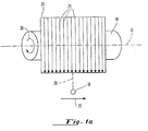
- the scanning means includes a drum rotatable about a drum axis and a head movable parallel with the axis in a predetermined direction such that the scanning motion of the head parallel to the axis is interruptable during continued rotation of the drum.
- a scanning control means is provided capable of inhibiting the writing means during the predetermined intervals.
- a facsimile receiver of the invention may be employed with a facsimile transmitter in which: sensor means detect dark-light variations on a document; modulator means coupled to the sensor means generate transmission signals representing the dark-light variations; and detector means demodulate handshake signals transmitted during the predetermined intervals when the transmission signals representing the dark-light variations are absent.
- the transmitting unit also includes scanning means coupled to the sensor means, and means for interrupting the scanning motion of the scanning means during the predetermined intervals.
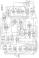
- the facsimile unit for transmitting signals representing dark-light variations in a document to a remote location is shown in block form.
- the document containing the dark-light variations is wrapped around a drum 10 which is rotated about its axis 12 by a drum drive 14 through a mechanical coupling depicted by a broken line 16.
- Mode signaling from the transmitter is also accomplished by varying the duration of the sync pulses as well as the time lapse between sync pulses.
- a mode encoder 54 is provided which is coupled to the operator select memory 44 and the sync pulse generator 34. The operator may therefore select a particular synchronizing pulse width to signal a particular mode. Different synchronizing pulse widths may be utilized to signal two different modes having the same drum speed but differing head speeds.
- the transmitter of Fig. 1 includes detector means for demodulating a ready to receive signal originating from and identifying the mode capabilities of a remotely located receiving unit.
- the detector means includes a receiver circuit 70 having an input coupled to the protective coupler 40 and an output coupled to a tone detector 72.
- the tone detector 72 is in turn coupled to a tone detector 74 having an output coupled to a ready to receive tone detector 76 which identifies the mode capabilities of the remotely located receiving unit.
- the output from the ready to receive tone detector 76 is coupled to the video select circuit 36, the operator select circuit 44 as well as the AM modulator 66 so as to permit the selection of AM modulation for transmitting the dark-light information should that be the choice of the operator of the sending unit.
- the particular intervals are determined at the handshake latch 78 in response to an output from the drum pulse counter 58.
- the counter 58 is also coupled to the handshake enable circuit 80.
- the handshake enable circuit 80 also enables the output enable circuit 42. Strobing of the handshake latch 78 at predetermined intervals to determine if the tone detector has detected a handshake signal is accomplished by the output of the drum pulse generator 30.
- the head speed encode circuit 52 is connected to the handshake enable circuit 80 so as to assure that the sensor motion and head drive will be inhibited during the predetermined interval as determined by the drum pulse counter 58.
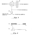
- the handshake signal is transmitted from the receiver in predetermined intervals when the received signals representing the dark-light variations of a document are absent. These intervals are determined by the drum pulse counter 159 which has an output which enables the AND gate 204 when a predetermined count has been reached. Since a drum pulse is generated after each rotation of the drum, the counter 204 will enable after a predetermined count, e.g., after a count of 46 revolutions of the drum. When the AND gate 204 is enabled, the counter 200 is reset and tach pulses from the drum drive 114 as shown in waveform a of fig. 4 begin to be counted in the counter 200. When the count reaches a predetermined level, the decoder 202 produces an output represented by the pulse shown in waveform b which continues for a predetermined length of time.
- the scanning motion of the receiver stylus 118 carried by the receiver head is interrupted during the interval time to to t 3 .
- This interruption is controlled by enabling the AND gate 204 and applying the output to the head speed encode circuitry 152.
- the head speed encode circuitry 152 then interrupts the scanning motion of the head parallel to the axis of the drum while the drum continues to rotate about the drum axis.
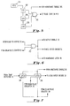
- an AND gate 212 is responsive to inputs from the ready to receive detector 76 and the drum pulse counter 58.
- the AND gate 212 is therefore only enabled when the output from the ready to receive detector 76 indicates that the receiving unit at the remote location is of a type capable of generating handshake signals and the drum pulse counter 58 has detected a count representing the predetermined interval in which the receiver will be transmitting the handshake signal, e.g., the 46th revolution of the drum 10.
Landscapes
- Engineering & Computer Science (AREA)
- Multimedia (AREA)
- Signal Processing (AREA)
- Facsimile Scanning Arrangements (AREA)
- Facsimile Transmission Control (AREA)
Claims (10)
Applications Claiming Priority (2)
| Application Number | Priority Date | Filing Date | Title |
|---|---|---|---|
| US05/886,136 US4238775A (en) | 1978-03-13 | 1978-03-13 | Facsimile receiver signaling |
| US886136 | 1997-06-30 |
Publications (2)
| Publication Number | Publication Date |
|---|---|
| EP0004200A1 EP0004200A1 (de) | 1979-09-19 |
| EP0004200B1 true EP0004200B1 (de) | 1981-09-23 |
Family
ID=25388453
Family Applications (1)
| Application Number | Title | Priority Date | Filing Date |
|---|---|---|---|
| EP79300391A Expired EP0004200B1 (de) | 1978-03-13 | 1979-03-13 | Faksimile-Empfänger |
Country Status (5)
| Country | Link |
|---|---|
| US (1) | US4238775A (de) |
| EP (1) | EP0004200B1 (de) |
| JP (1) | JPS54127211A (de) |
| CA (1) | CA1133630A (de) |
| DE (1) | DE2960868D1 (de) |
Families Citing this family (4)
| Publication number | Priority date | Publication date | Assignee | Title |
|---|---|---|---|---|
| US4346410A (en) * | 1979-04-17 | 1982-08-24 | Matsushita Graphic Communications Systems, Inc. | Facsimile receiver |
| US5065427A (en) * | 1989-10-31 | 1991-11-12 | Vishwas Godbole | Fax/data call receiving system and method |
| US6771697B1 (en) * | 1998-06-23 | 2004-08-03 | Pctel, Inc. | Spread spectrum handshake for digital subscriber line telecommunications systems |
| US9994179B2 (en) * | 2012-07-25 | 2018-06-12 | Infineon Technologies Austria Ag | Circuit arrangements and a method for receiving information |
Family Cites Families (5)
| Publication number | Priority date | Publication date | Assignee | Title |
|---|---|---|---|---|
| US3441665A (en) * | 1965-11-10 | 1969-04-29 | Xerox Corp | Transmission system utilizing a single cable for accomplishing forward transmission and reverse supervisory control signalling |
| US3496287A (en) * | 1965-12-27 | 1970-02-17 | Xerox Corp | Supervisory signalling apparatus for graphic communication systems |
| US3614319A (en) * | 1969-02-24 | 1971-10-19 | Graphic Sciences Inc | Telephonic transmission of data in graphic form |
| US3914537A (en) * | 1972-05-16 | 1975-10-21 | Xerox Corp | Facsimile communication system |
| JPS5926152B2 (ja) * | 1974-03-16 | 1984-06-25 | 株式会社リコー | フアクシミリ通信方式およびその装置 |
-
1978
- 1978-03-13 US US05/886,136 patent/US4238775A/en not_active Expired - Lifetime
-
1979
- 1979-03-12 CA CA323,235A patent/CA1133630A/en not_active Expired
- 1979-03-13 JP JP2928479A patent/JPS54127211A/ja active Pending
- 1979-03-13 EP EP79300391A patent/EP0004200B1/de not_active Expired
- 1979-03-13 DE DE7979300391T patent/DE2960868D1/de not_active Expired
Also Published As
| Publication number | Publication date |
|---|---|
| EP0004200A1 (de) | 1979-09-19 |
| CA1133630A (en) | 1982-10-12 |
| US4238775A (en) | 1980-12-09 |
| JPS54127211A (en) | 1979-10-03 |
| DE2960868D1 (en) | 1981-12-10 |
Similar Documents
| Publication | Publication Date | Title |
|---|---|---|
| CA1108288A (en) | Facsimile communication system | |
| US4236248A (en) | Transmission speed switching system | |
| GB2157924A (en) | Data communication apparatus | |
| GB1338653A (en) | Adaptive multiple speed facsimile system | |
| US4112467A (en) | Failure mode control apparatus for electronic graphic data transmission system | |
| CA1156348A (en) | Facsimile signalling method | |
| EP0004200B1 (de) | Faksimile-Empfänger | |
| EP0004201B1 (de) | Faksimile- Übertragungseinheit | |
| US4244007A (en) | Facsimile receiver signalling | |
| US5911037A (en) | Multiple copy in a facsimile system | |
| US3974326A (en) | Facsimile communication system | |
| US4270147A (en) | Apparatus for limiting facsimile transmission durations | |
| JPS5952863B2 (ja) | フアクシミリ装置の送信モ−ド自動切換方式 | |
| CA1161155A (en) | Internal test method and apparatus for facsimile tansceiver | |
| US5729355A (en) | Facsimile machine having a phase/amplitude fluctuation detector | |
| US5774231A (en) | Facsimile apparatus which changes the generation time of one line of read data | |
| JPS59205841A (ja) | デ−タ伝送速度制御方式 | |
| JP2752811B2 (ja) | 伝送速度切替方式 | |
| US4331984A (en) | Method and apparatus for synchronizing facsimile transmissions | |
| JPS62123872A (ja) | フアクシミリ装置の送信レベル決定方式 | |
| JPS5792975A (en) | Facsimile communication system | |
| JPS5922479A (ja) | フアクシミリ装置 | |
| JPH0350474B2 (de) | ||
| JPS62283771A (ja) | データ通信装置 | |
| JPH01185072A (ja) | 画像通信装置 |
Legal Events
| Date | Code | Title | Description |
|---|---|---|---|
| PUAI | Public reference made under article 153(3) epc to a published international application that has entered the european phase |
Free format text: ORIGINAL CODE: 0009012 |
|
| AK | Designated contracting states |
Designated state(s): DE FR GB IT NL |
|
| 17P | Request for examination filed | ||
| ITF | It: translation for a ep patent filed | ||
| GRAA | (expected) grant |
Free format text: ORIGINAL CODE: 0009210 |
|
| AK | Designated contracting states |
Designated state(s): DE FR GB IT NL |
|
| REF | Corresponds to: |
Ref document number: 2960868 Country of ref document: DE Date of ref document: 19811210 |
|
| PGFP | Annual fee paid to national office [announced via postgrant information from national office to epo] |
Ref country code: DE Payment date: 19831213 Year of fee payment: 6 |
|
| PGFP | Annual fee paid to national office [announced via postgrant information from national office to epo] |
Ref country code: NL Payment date: 19831215 Year of fee payment: 6 Ref country code: FR Payment date: 19831215 Year of fee payment: 6 |
|
| PG25 | Lapsed in a contracting state [announced via postgrant information from national office to epo] |
Ref country code: NL Effective date: 19851001 |
|
| GBPC | Gb: european patent ceased through non-payment of renewal fee | ||
| PG25 | Lapsed in a contracting state [announced via postgrant information from national office to epo] |
Ref country code: DE Effective date: 19851203 |
|
| NLV4 | Nl: lapsed or anulled due to non-payment of the annual fee | ||
| PG25 | Lapsed in a contracting state [announced via postgrant information from national office to epo] |
Ref country code: FR Free format text: LAPSE BECAUSE OF NON-PAYMENT OF DUE FEES Effective date: 19861128 |
|
| REG | Reference to a national code |
Ref country code: FR Ref legal event code: ST |
|
| PG25 | Lapsed in a contracting state [announced via postgrant information from national office to epo] |
Ref country code: GB Effective date: 19881117 |
|
| PLBE | No opposition filed within time limit |
Free format text: ORIGINAL CODE: 0009261 |
|
| STAA | Information on the status of an ep patent application or granted ep patent |
Free format text: STATUS: NO OPPOSITION FILED WITHIN TIME LIMIT |