EP0004337A2 - Dispositif pour le développement de plaques à imprimer comportant des rouleaux horizontaux supérieurs et inférieurs disposés par paire - Google Patents
Dispositif pour le développement de plaques à imprimer comportant des rouleaux horizontaux supérieurs et inférieurs disposés par paire Download PDFInfo
- Publication number
- EP0004337A2 EP0004337A2 EP79100771A EP79100771A EP0004337A2 EP 0004337 A2 EP0004337 A2 EP 0004337A2 EP 79100771 A EP79100771 A EP 79100771A EP 79100771 A EP79100771 A EP 79100771A EP 0004337 A2 EP0004337 A2 EP 0004337A2
- Authority
- EP
- European Patent Office
- Prior art keywords
- bearing
- roller
- rollers
- printing plates
- shaft
- Prior art date
- Legal status (The legal status is an assumption and is not a legal conclusion. Google has not performed a legal analysis and makes no representation as to the accuracy of the status listed.)
- Granted
Links
Images

Classifications
-
- G—PHYSICS
- G03—PHOTOGRAPHY; CINEMATOGRAPHY; ANALOGOUS TECHNIQUES USING WAVES OTHER THAN OPTICAL WAVES; ELECTROGRAPHY; HOLOGRAPHY
- G03F—PHOTOMECHANICAL PRODUCTION OF TEXTURED OR PATTERNED SURFACES, e.g. FOR PRINTING, FOR PROCESSING OF SEMICONDUCTOR DEVICES; MATERIALS THEREFOR; ORIGINALS THEREFOR; APPARATUS SPECIALLY ADAPTED THEREFOR
- G03F7/00—Photomechanical, e.g. photolithographic, production of textured or patterned surfaces, e.g. printing surfaces; Materials therefor, e.g. comprising photoresists; Apparatus specially adapted therefor
- G03F7/26—Processing photosensitive materials; Apparatus therefor
- G03F7/30—Imagewise removal using liquid means
- G03F7/3042—Imagewise removal using liquid means from printing plates transported horizontally through the processing stations
- G03F7/3064—Imagewise removal using liquid means from printing plates transported horizontally through the processing stations characterised by the transport means or means for confining the different units, e.g. to avoid the overflow
-
- G—PHYSICS
- G03—PHOTOGRAPHY; CINEMATOGRAPHY; ANALOGOUS TECHNIQUES USING WAVES OTHER THAN OPTICAL WAVES; ELECTROGRAPHY; HOLOGRAPHY
- G03D—APPARATUS FOR PROCESSING EXPOSED PHOTOGRAPHIC MATERIALS; ACCESSORIES THEREFOR
- G03D3/00—Liquid processing apparatus involving immersion; Washing apparatus involving immersion
- G03D3/08—Liquid processing apparatus involving immersion; Washing apparatus involving immersion having progressive mechanical movement of exposed material
- G03D3/13—Liquid processing apparatus involving immersion; Washing apparatus involving immersion having progressive mechanical movement of exposed material for long films or prints in the shape of strips, e.g. fed by roller assembly
- G03D3/132—Liquid processing apparatus involving immersion; Washing apparatus involving immersion having progressive mechanical movement of exposed material for long films or prints in the shape of strips, e.g. fed by roller assembly fed by roller assembly
Definitions
- the invention relates to a device for developing printing plates with pairs, in particular horizontally arranged upper and lower rollers for transporting the printing plates and optionally for squeezing off residual liquid adhering to the printing plates, with one liftable at each end of each upper roller with respect to the lower roller and lowerable bearing, which can be operated via a toggle lever arrangement.
- This device has the disadvantage that for lifting the upper rollers, which must be operated before long downtimes, for example overnight or over a weekend, a large number of actuating handles, since each end of each upper roller is assigned a separate actuating handle. This operation is cumbersome and time-consuming, so there is a temptation to occasionally refrain from operating it.
- the rollers of the roller pairs remain pressed together for long periods of inactivity, e.g. overnight or over a weekend, deformations of their surfaces can occur, which can endanger the safe and gentle transport of the printing plates and perfect fluid squeezing, especially in horizontal processing plants.
- the prior art also includes a device for developing printing plates with rollers arranged in pairs, the ends of which are mounted in side plates. These side plates are divided and equipped by means of a pivot point assigned to the upper side plate and corresponding lifting elements in such a way that the entire upper part of the side plates or the processing zone, including all of the upper rollers, can be raised.
- This device is relatively complex, in particular when the lifting should not require too much effort from the operator.
- this arrangement cannot be used for those facilities that have a plurality of treatment stations have, wherein each treatment station is designed as a structural unit that can be assembled with other structural units to form the entire facility.
- the present invention is therefore based on the object to provide a device for developing printing plates with rollers arranged in pairs of the type mentioned, which is easy and convenient to operate reliably in such a way that all upper rollers are forcibly lifted off.
- the effort required for this should be as low as possible.
- this device should also be suitable for those applications in which the device is composed of several units, each of which embodies a processing station.
- the invention is based on a device for developing printing plates with paired, in particular horizontally arranged upper and lower rollers for transporting the printing plates and optionally for squeezing off residual liquid adhering to the printing plates, with one liftable at each end of each upper roller with respect to the lower roller and a lowerable bearing which can be actuated via a toggle lever arrangement.
- the device according to the invention is characterized in that a pivotable fork head with an upper and a lower arm is provided for attacking the bearings of the upper rollers, the pivot axis of which is directed parallel to the pressure plate transport direction, the upper arm of which is caused by the toggle lever arrangement in the lowered state of the bearing presses on the bearing and the lower arm of which supports the bearing in the raised state, that a first end of each toggle lever arrangement is connected to the fork head and that a second end of each toggle lever arrangement is connected to a rotatable control shaft common to all toggle lever arrangements, which is also parallel to the Printing plate transport direction is stored.
- the pivot axes of the pivotable fork heads are directed parallel to the printing plate transport direction, ie at right angles to the main axis of the rollers.
- the toggle lever arrangements acting on the fork heads each lie in a plane through which the main axis of the roller to be lifted runs and lead to the control shaft, which is also mounted parallel to the pressure plate transport direction. All toggle lever assemblies on one side of all should be removed from the selector shaft lifting rollers attached so that the bearings of these rollers can be raised on one side by a single rotary movement of the control shaft. The same applies to the actuation of the bearings on the opposite side of the rollers.
- the device according to the invention is characterized in that the bearings of the rollers are not firmly connected to the fork heads or corresponding parts, but that the fork heads engage the bearings with an upper and lower arm each such that the upper rollers in the raised state can be easily removed from the device and reinserted.
- This fastening of the bearings which becomes self-releasing when the bearings are lifted, enables simple maintenance and, if necessary, repair of the device, since the lower rollers are particularly easily accessible after removal of the upper rollers.
- each treatment station being designed as a structural unit that can be combined with further structural units to form the device, it is advantageously provided that a section in each structural unit the shift shaft is mounted with a Section of the switching shaft of the adjacent structural unit can be coupled via a cross coupling piece.
- each unit of the device which can also be designated as a module and can be combined with other units, is permanently assigned a section of the selector shaft with a cross coupling piece, so that a continuous selector shaft results when the units are assembled.
- a shift lever is mounted at one end of the shift shaft, which is in a rotationally fixed connection with the shift shaft.
- this has the further feature that a locking plate is connected to the selector shaft, to which a pressure piece with a spring-loaded ball is pressed.
- the shift shaft can be brought into two defined shift positions, namely into a first position in which the upper rollers are pressed onto the lower rollers and in a second position in which the upper rollers can be lifted off the lower rollers. In the latter position, the pressure piece resting on the locking plate can also ensure that the rollers are held in their upper position.
- the fork head with its upper and lower arm is arranged in a vertical plane in which the central axis of the associated roller lies and that a guide bearing with two side arms in a horizontal plane in which the central axis of the The roller is fixed in place so that the side arms encompass the bearing that is vertically displaceable relative to them.
- each bearing is therefore held on at least three sides, namely on two sides lying in the printing plate transport direction and - in the raised state - from below or - in the lowered state - from above.
- This arrangement is advantageously made so that the rollers can be lifted out in the raised position of the fork head and can be used again between the two side arms of the guide bearing.
- the upper arm of the fork head only presses on the bearing when the upper roller is to be pressed onto the lower roller.
- the device is expediently designed in such a way that a pressure roller is rotatably mounted on the upper arm and that a lifting roller is rotatably mounted on the lower arm.
- the toggle lever arrangement has a knee joint lever which can be connected in a rotationally fixed manner to the switching shaft and is connected to a first threaded rod via a knee joint bearing, and that the first threaded rod is connected to a second threaded rod via a turnbuckle nut, at the end of which the fork head is pivotally mounted, and that the first threaded rod can be rotated with a right-hand thread in the turnbuckle nut and the second threaded rod can also be rotated in the turnbuckle nut with a left-hand thread.
- the turnbuckle can be turned
- the pressure of the upper rollers on the lower rollers can be adjusted, and the height of the lifting of the upper rollers from the lower rollers can be adjusted.
- a support ring is provided on each bearing, which comprises a ball bearing seated on the stub shaft of the roller.
- the support ring By means of this support ring, the forces originating from the arms of the fork head and from the side arms of the guide bearing can be distributed evenly over the outer ring of the ball bearing.
- the support ring makes it possible to adapt different ball bearing diameters to the dimensions of the fork head and the guide bearing.
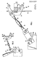
- Fig. 1, 1, 2, 3 designate three structural units, each embodying a copying station.
- a development station, a washing station and a station for applying a protective layer to the developed and watered printing plate are seen in the transport direction T.
- the actual processing elements are not visible, which can consist of spray tubes, doctor blades and brush rollers, but pairs of rollers, which are used to transport the printing plates through the device and optionally to squeeze residual liquid from the printing plates.
- the upper rollers 4, 5 can be seen in the first structural unit, and the upper rollers 6 and 7 in the structural units 2 and 3, respectively.
- the rollers 4 to 7 are on their left side, each with a bearing 8 to 11 stored, which is held in a manner to be described in each case a side plate 12, 13, 14 of each structural unit.
- Each of the bearings 8 to 11 is coupled via a toggle lever arrangement 15 to 18 to a switching shaft 19 which is mounted on the device parallel to the transport direction T.
- the selector shaft consists of three sections 20, 21, 22, each of which is assigned to a structural unit and is connected to one another in a rotationally fixed manner via a cross coupling piece 23 or 24.
- a shift lever 25 is attached to its front section as an actuating member.
- FIG. 1 shows only a left section of the device for developing printing plates, to which a right section constructed in the same way is connected on the right.
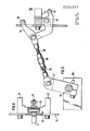
- the toggle lever arrangement 15 is in such a position, that an upper arm 33 of the clevis is not provided bearing, which it includes together with a lower arm 34, depressed such that the upper roller is pressed onto the associated roller with the desired contact pressure.
- the bearing, not shown, of the upper roller is raised by the lower arm 34 of the fork head, so that the upper roller lifts off the lower roller.
- This setting is made by pivoting the shift lever 25 to the left, through which the knee joint lever 26 is also pivoted to the left.
- the fork head is pivoted back counterclockwise about the pivot axis 32, the upper arm 33 simultaneously withdrawing so far that the bearing, not shown, is released for lifting upwards together with the upper roller.
- the toggle lever arrangement 15 comprises a total of the toggle lever 26, the knee joint bearing 27, the first threaded rod 28, the turnbuckle nut 29 and the second threaded rod 30.
- the first end of the toggle lever arrangement 35 engages a bearing 36 of the fork head, while the toggle lever 26 abuts a stop pin 36a which is embedded in a bearing 37 of the selector shaft.
- the knee joint lever 26 clamped to the section 20 of the selector shaft is pivoted to the right, so that the fork head is pivoted into the position required for pressing the upper roller onto the lower roller.
- a pressure roller 38 is mounted on the upper arm 33 of the fork head, while a lifting roller 39 is mounted on the lower arm 34.
- a guide bearing 40 is fastened to the circuit board 12, so that the bearing of the upper roller, not shown, of two side arms 41 and 42 of the guide bearing, cf. Fig. 9 is included.
- the pivot axis 32 is embedded in a lower section of the guide bearing.
- the toggle lever arrangement is in the switch position for relieving the rollers, the bearing of the upper roller, not shown, being raised by the lifting roller 39.
- the upper bearing is guided between the side arms 41, 42 of the guide bearing, cf. Fig. 10.
- the pressure of the rollers in the lowered state of the upper arm 33 or the amount of lifting of the upper roller by the lower arm 34 can be adjusted.
- Fig. 6 in which the guide bearing 40 is shown with its side arms 41 and 42 in a view from below, the broken-open bearing can be particularly well shown recognize the fork head 31 about the pivot axis 32.
- the fork head and the guide bearing thus form a unit that can be connected to the side plate 12.
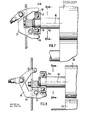
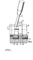
- FIG. 7 From Fig. 7 it can be seen how the fork head 31 presses down the bearing seated on the stub shaft 45 so that the upper roller 4 is pressed onto the associated lower roller 46.
- This switch position is shown in FIG. 9 in a view of the cross section corresponding to section line AB in FIG. 7. From these two figures it can also be seen that the actual bearing 15ain is surrounded by a support ring 47. The upper pressure roller 38 and the lower lifting roller 39 can roll on this support ring.
- the fork head 31 is in its position for relieving the rollers 4 and 46 of a pair of rollers, the upper roller 4 being raised by the amount x.
- the liftable parts of the device in this switch position are shown from a view of the section along the line AB in Fig. 10.
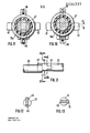
- a cross coupling piece 23 for coupling the sections 20 and 21 of the selector shaft can be seen in its details. After that is off the forehead side of the selector shaft 20, a groove 48 is recessed into which a sliding finger 49 of an intermediate piece 50 extends. The intermediate piece is inserted with a finger 51 into a groove 52 in section 21 of the selector shaft.
- FIG 14 shows how the shift lever 25 is let into the section 20 of the shift shaft, which in turn is mounted in a bearing 53 for the shift lever.
- a locking plate 54 is also rotatably connected, which cooperates with two pressure pieces 55 and 56.
- the pressure pieces are used to fix the selector shaft in the position in which the selector shaft is rotated to lift the upper rollers.
- the pressure pieces each comprise a ball 58 or 59 pressed into a bore 57 of the snap-in plate, which is in each case under the force of a pressure spring accommodated in each pressure piece.
Landscapes
- Physics & Mathematics (AREA)
- General Physics & Mathematics (AREA)
- Inking, Control Or Cleaning Of Printing Machines (AREA)
- Rolls And Other Rotary Bodies (AREA)
- Manufacture Or Reproduction Of Printing Formes (AREA)
- Photosensitive Polymer And Photoresist Processing (AREA)
Applications Claiming Priority (2)
| Application Number | Priority Date | Filing Date | Title |
|---|---|---|---|
| DE2812688 | 1978-03-23 | ||
| DE19782812688 DE2812688A1 (de) | 1978-03-23 | 1978-03-23 | Einrichtung zum entwickeln von druckplatten mit paarweise angeordneten oberen und unteren walzen |
Publications (3)
| Publication Number | Publication Date |
|---|---|
| EP0004337A2 true EP0004337A2 (fr) | 1979-10-03 |
| EP0004337A3 EP0004337A3 (en) | 1979-10-17 |
| EP0004337B1 EP0004337B1 (fr) | 1981-11-11 |
Family
ID=6035249
Family Applications (1)
| Application Number | Title | Priority Date | Filing Date |
|---|---|---|---|
| EP79100771A Expired EP0004337B1 (fr) | 1978-03-23 | 1979-03-15 | Dispositif pour le développement de plaques à imprimer comportant des rouleaux horizontaux supérieurs et inférieurs disposés par paire |
Country Status (6)
| Country | Link |
|---|---|
| US (1) | US4206527A (fr) |
| EP (1) | EP0004337B1 (fr) |
| AT (1) | AT376821B (fr) |
| CA (1) | CA1108965A (fr) |
| DE (2) | DE2812688A1 (fr) |
| ES (1) | ES478920A1 (fr) |
Cited By (4)
| Publication number | Priority date | Publication date | Assignee | Title |
|---|---|---|---|---|
| EP0110256A1 (fr) * | 1982-11-26 | 1984-06-13 | Hoechst Aktiengesellschaft | Dispositif de pression et de soulèvement |
| EP0177873A1 (fr) * | 1984-10-09 | 1986-04-16 | Hoechst Aktiengesellschaft | Dispositif de pression et de l'enlèvement de rouleaux |
| US4695147A (en) * | 1985-12-23 | 1987-09-22 | Eastman Kodak Company | Apparatus and method for preventing the formation of a deposit from a processing solution on a film transport member |
| EP0633498A1 (fr) * | 1993-07-05 | 1995-01-11 | Agfa-Gevaert N.V. | Dispositif de développement photographique |
Families Citing this family (1)
| Publication number | Priority date | Publication date | Assignee | Title |
|---|---|---|---|---|
| US4349932A (en) * | 1980-04-18 | 1982-09-21 | Hoechst Aktiengesellschaft | Device for uniformly pressing on and releasing the pressure from rub-out bars |
Family Cites Families (8)
| Publication number | Priority date | Publication date | Assignee | Title |
|---|---|---|---|---|
| GB408441A (en) * | 1933-03-13 | 1934-04-12 | Joseph Thomas Pearce Bailey | Improvements in means for applying ink, colour or other printing fluid to the printing rollers of printing machines |
| GB620148A (en) * | 1945-05-22 | 1949-03-21 | Goss Printing Press Co Ltd | Improvements in or relating to inking mechanisms for printing presses |
| DE912816C (de) * | 1952-04-10 | 1954-06-03 | Maschf Augsburg Nuernberg Ag | Vorrichtung zum Anstellen und zur Kontrolle der Farb- und Auftragwalzen an Druckmaschinen |
| DE1052799B (de) | 1955-09-20 | 1959-03-12 | Steinmesse & Stollberg K G | Vorrichtung zum Anstellen der Gegendruckwalze an die Glaettwalze von Kalandern |
| US3055242A (en) * | 1960-07-05 | 1962-09-25 | Morgan Construction Co | Rolling mills |
| DE1240530B (de) * | 1963-07-19 | 1967-05-18 | Maschf Augsburg Nuernberg Ag | Lagerung fuer Auftrag- und Reibwalzen in Farbwerken fuer Rotationsdruckmaschinen |
| US3252311A (en) * | 1964-05-06 | 1966-05-24 | Whirlpool Co | Power reset mechanism for wringers |
| DE2326122B2 (de) * | 1972-05-26 | 1978-04-13 | Joergen Virum Bech (Daenemark) | Maschine zum Entwickeln von Offset-Druckplatten |
-
1978
- 1978-03-23 DE DE19782812688 patent/DE2812688A1/de not_active Withdrawn
-
1979
- 1979-03-15 EP EP79100771A patent/EP0004337B1/fr not_active Expired
- 1979-03-15 DE DE7979100771T patent/DE2961296D1/de not_active Expired
- 1979-03-20 CA CA323,800A patent/CA1108965A/fr not_active Expired
- 1979-03-21 AT AT0212979A patent/AT376821B/de not_active IP Right Cessation
- 1979-03-22 US US06/022,887 patent/US4206527A/en not_active Expired - Lifetime
- 1979-03-23 ES ES478920A patent/ES478920A1/es not_active Expired
Cited By (4)
| Publication number | Priority date | Publication date | Assignee | Title |
|---|---|---|---|---|
| EP0110256A1 (fr) * | 1982-11-26 | 1984-06-13 | Hoechst Aktiengesellschaft | Dispositif de pression et de soulèvement |
| EP0177873A1 (fr) * | 1984-10-09 | 1986-04-16 | Hoechst Aktiengesellschaft | Dispositif de pression et de l'enlèvement de rouleaux |
| US4695147A (en) * | 1985-12-23 | 1987-09-22 | Eastman Kodak Company | Apparatus and method for preventing the formation of a deposit from a processing solution on a film transport member |
| EP0633498A1 (fr) * | 1993-07-05 | 1995-01-11 | Agfa-Gevaert N.V. | Dispositif de développement photographique |
Also Published As
| Publication number | Publication date |
|---|---|
| ATA212979A (de) | 1984-05-15 |
| EP0004337B1 (fr) | 1981-11-11 |
| EP0004337A3 (en) | 1979-10-17 |
| CA1108965A (fr) | 1981-09-15 |
| ES478920A1 (es) | 1980-01-01 |
| AT376821B (de) | 1985-01-10 |
| US4206527A (en) | 1980-06-10 |
| DE2961296D1 (en) | 1982-01-14 |
| DE2812688A1 (de) | 1979-10-04 |
Similar Documents
| Publication | Publication Date | Title |
|---|---|---|
| DE3022376C2 (de) | Kniehebelspannvorrichtung zum Festspannen von Werkstücken | |
| DE3417158A1 (de) | Vorrichtung zum trennen von paletten auf einer rollenbahn | |
| DE1510215B1 (de) | Presswalzenteil mit gekreuzten Walzen | |
| DE2716327A1 (de) | Transportvorrichtung | |
| DE3207622A1 (de) | Vorrichtung zum an-, ab- und einstellen von auftragwalzen am plattenzylinder von druckmaschinen | |
| DE2643017C3 (de) | Durchbiegungseinstellwalze für Papiermaschinen | |
| DE2019352C3 (de) | Oberwalzen-Trag- und Belastungsvorrichtung | |
| EP0004337B1 (fr) | Dispositif pour le développement de plaques à imprimer comportant des rouleaux horizontaux supérieurs et inférieurs disposés par paire | |
| DE2835514B1 (de) | Vorrichtung zum axialen Verschieben von konischen Zwischenwalzen in einem Mehrrollen-Walzgeruest | |
| DE4114313A1 (de) | Laminator | |
| DE3610889C2 (de) | Mehrwalzen-Gerüst | |
| DE1611778A1 (de) | Druckwalzenbalken in einem Laengsschneider fuer Papier | |
| DE69912076T2 (de) | Schrägwalzwerk | |
| EP0177873B1 (fr) | Dispositif de pression et de l'enlèvement de rouleaux | |
| DE19829875A1 (de) | Vorrichtung zum Spannen einer Kante einer Platte für eine Druckmaschine | |
| DE3838746A1 (de) | Kalander fuer die oberflaechenbehandlung von papierbahnen | |
| EP0315818B1 (fr) | Machine pour impression sérigraphique | |
| DE3720001A1 (de) | Vakuumventil | |
| DE2643018B2 (de) | Walzenpresse mit einer Durchbiegungseinstellwalze z.B. für Papiermaschinen | |
| DE3018997C2 (de) | Vorrichtung zum Auswechseln der Arbeitswalzen von Walzgerüsten | |
| DE3235556C2 (fr) | ||
| DE29803330U1 (de) | Hubvorrichtung | |
| DE2126697A1 (de) | Vorrichtung mit Spindelantrieb zum Anheben von Papierrollen und dergleichen schweren zylindrischen Gegenständen | |
| DE2805353C2 (de) | Baumschneidevorrichtung mit zwei über Kurbelarme gegenläufig verschwenkbaren Scherblättern | |
| DE3436998C2 (de) | Druckmittelbetätigte Schere |
Legal Events
| Date | Code | Title | Description |
|---|---|---|---|
| PUAI | Public reference made under article 153(3) epc to a published international application that has entered the european phase |
Free format text: ORIGINAL CODE: 0009012 |
|
| PUAL | Search report despatched |
Free format text: ORIGINAL CODE: 0009013 |
|
| AK | Designated contracting states |
Designated state(s): BE DE FR GB IT NL SE |
|
| AK | Designated contracting states |
Designated state(s): BE DE FR GB IT NL SE |
|
| 17P | Request for examination filed | ||
| ITF | It: translation for a ep patent filed | ||
| GRAA | (expected) grant |
Free format text: ORIGINAL CODE: 0009210 |
|
| AK | Designated contracting states |
Designated state(s): BE DE FR GB IT NL SE |
|
| REF | Corresponds to: |
Ref document number: 2961296 Country of ref document: DE Date of ref document: 19820114 |
|
| PGFP | Annual fee paid to national office [announced via postgrant information from national office to epo] |
Ref country code: FR Payment date: 19920214 Year of fee payment: 14 |
|
| PGFP | Annual fee paid to national office [announced via postgrant information from national office to epo] |
Ref country code: SE Payment date: 19920221 Year of fee payment: 14 Ref country code: GB Payment date: 19920221 Year of fee payment: 14 |
|
| PGFP | Annual fee paid to national office [announced via postgrant information from national office to epo] |
Ref country code: BE Payment date: 19920311 Year of fee payment: 14 |
|
| ITTA | It: last paid annual fee | ||
| PGFP | Annual fee paid to national office [announced via postgrant information from national office to epo] |
Ref country code: NL Payment date: 19920331 Year of fee payment: 14 |
|
| PGFP | Annual fee paid to national office [announced via postgrant information from national office to epo] |
Ref country code: DE Payment date: 19920513 Year of fee payment: 14 |
|
| PG25 | Lapsed in a contracting state [announced via postgrant information from national office to epo] |
Ref country code: GB Effective date: 19930315 |
|
| PG25 | Lapsed in a contracting state [announced via postgrant information from national office to epo] |
Ref country code: SE Effective date: 19930316 |
|
| PG25 | Lapsed in a contracting state [announced via postgrant information from national office to epo] |
Ref country code: BE Effective date: 19930331 |
|
| BERE | Be: lapsed |
Owner name: HOECHST A.G. Effective date: 19930331 |
|
| PG25 | Lapsed in a contracting state [announced via postgrant information from national office to epo] |
Ref country code: NL Effective date: 19931001 |
|
| GBPC | Gb: european patent ceased through non-payment of renewal fee |
Effective date: 19930315 |
|
| NLV4 | Nl: lapsed or anulled due to non-payment of the annual fee | ||
| PG25 | Lapsed in a contracting state [announced via postgrant information from national office to epo] |
Ref country code: FR Effective date: 19931130 |
|
| PG25 | Lapsed in a contracting state [announced via postgrant information from national office to epo] |
Ref country code: DE Effective date: 19931201 |
|
| REG | Reference to a national code |
Ref country code: FR Ref legal event code: ST |
|
| EUG | Se: european patent has lapsed |
Ref document number: 79100771.9 Effective date: 19931008 |
|
| PLBE | No opposition filed within time limit |
Free format text: ORIGINAL CODE: 0009261 |
|
| STAA | Information on the status of an ep patent application or granted ep patent |
Free format text: STATUS: NO OPPOSITION FILED WITHIN TIME LIMIT |