EP0004361B1 - Transmission à commande manuelle avec un arbre de commande unique et à rapport de vitesses surmultiplié - Google Patents
Transmission à commande manuelle avec un arbre de commande unique et à rapport de vitesses surmultiplié Download PDFInfo
- Publication number
- EP0004361B1 EP0004361B1 EP79100821A EP79100821A EP0004361B1 EP 0004361 B1 EP0004361 B1 EP 0004361B1 EP 79100821 A EP79100821 A EP 79100821A EP 79100821 A EP79100821 A EP 79100821A EP 0004361 B1 EP0004361 B1 EP 0004361B1
- Authority
- EP
- European Patent Office
- Prior art keywords
- shift
- cane
- rail
- gear
- shift rail
- Prior art date
- Legal status (The legal status is an assumption and is not a legal conclusion. Google has not performed a legal analysis and makes no representation as to the accuracy of the status listed.)
- Expired
Links
- 230000005540 biological transmission Effects 0.000 title claims description 22
- 230000033001 locomotion Effects 0.000 claims description 24
- 230000010355 oscillation Effects 0.000 claims 6
- 238000005266 casting Methods 0.000 description 3
- 239000000428 dust Substances 0.000 description 3
- 230000007935 neutral effect Effects 0.000 description 3
- 238000009434 installation Methods 0.000 description 2
- 239000004677 Nylon Substances 0.000 description 1
- 238000002485 combustion reaction Methods 0.000 description 1
- 150000001875 compounds Chemical class 0.000 description 1
- 239000002184 metal Substances 0.000 description 1
- 229920001778 nylon Polymers 0.000 description 1
- 230000000284 resting effect Effects 0.000 description 1
- 238000007789 sealing Methods 0.000 description 1
Images




Classifications
-
- F—MECHANICAL ENGINEERING; LIGHTING; HEATING; WEAPONS; BLASTING
- F16—ENGINEERING ELEMENTS AND UNITS; GENERAL MEASURES FOR PRODUCING AND MAINTAINING EFFECTIVE FUNCTIONING OF MACHINES OR INSTALLATIONS; THERMAL INSULATION IN GENERAL
- F16H—GEARING
- F16H63/00—Control outputs from the control unit to change-speed- or reversing-gearings for conveying rotary motion or to other devices than the final output mechanism
- F16H63/02—Final output mechanisms therefor; Actuating means for the final output mechanisms
- F16H63/08—Multiple final output mechanisms being moved by a single common final actuating mechanism
- F16H63/20—Multiple final output mechanisms being moved by a single common final actuating mechanism with preselection and subsequent movement of each final output mechanism by movement of the final actuating mechanism in two different ways, e.g. guided by a shift gate
-
- F—MECHANICAL ENGINEERING; LIGHTING; HEATING; WEAPONS; BLASTING
- F16—ENGINEERING ELEMENTS AND UNITS; GENERAL MEASURES FOR PRODUCING AND MAINTAINING EFFECTIVE FUNCTIONING OF MACHINES OR INSTALLATIONS; THERMAL INSULATION IN GENERAL
- F16H—GEARING
- F16H63/00—Control outputs from the control unit to change-speed- or reversing-gearings for conveying rotary motion or to other devices than the final output mechanism
- F16H63/02—Final output mechanisms therefor; Actuating means for the final output mechanisms
- F16H63/30—Constructional features of the final output mechanisms
-
- Y—GENERAL TAGGING OF NEW TECHNOLOGICAL DEVELOPMENTS; GENERAL TAGGING OF CROSS-SECTIONAL TECHNOLOGIES SPANNING OVER SEVERAL SECTIONS OF THE IPC; TECHNICAL SUBJECTS COVERED BY FORMER USPC CROSS-REFERENCE ART COLLECTIONS [XRACs] AND DIGESTS
- Y10—TECHNICAL SUBJECTS COVERED BY FORMER USPC
- Y10T—TECHNICAL SUBJECTS COVERED BY FORMER US CLASSIFICATION
- Y10T74/00—Machine element or mechanism
- Y10T74/19—Gearing
- Y10T74/19219—Interchangeably locked
- Y10T74/19284—Meshing assisters
-
- Y—GENERAL TAGGING OF NEW TECHNOLOGICAL DEVELOPMENTS; GENERAL TAGGING OF CROSS-SECTIONAL TECHNOLOGIES SPANNING OVER SEVERAL SECTIONS OF THE IPC; TECHNICAL SUBJECTS COVERED BY FORMER USPC CROSS-REFERENCE ART COLLECTIONS [XRACs] AND DIGESTS
- Y10—TECHNICAL SUBJECTS COVERED BY FORMER USPC
- Y10T—TECHNICAL SUBJECTS COVERED BY FORMER US CLASSIFICATION
- Y10T74/00—Machine element or mechanism
- Y10T74/20—Control lever and linkage systems
- Y10T74/20012—Multiple controlled elements
- Y10T74/20018—Transmission control
Definitions
- the invention relates to an improvement in a single shift rail manual transmission according to the prior art portion of the claim.
- a transmission mechanism of this kind is known from GB-A-1 053 353 (Ford) wherein a single shift rail is extending in the longitudinal direction of the transmission and is arranged above the input- and the aligned output shafts.
- a single shift rail is normally actuated by a shift cane the pivot point of which is mounted in a cane housing formed on a transmission extension housing bolted to the rearward wall of the transmission housing.
- the object of the invention is to provide a single shift rail manual transmission of the kind referred to above with an improved supporting structure which enables an arrangement of the shift rail adjacent to the input- and output shafts of the transmission and the mounting of the shift cane at any one of several longitudinal locations depending upon the requirements of the particular driveline installation of a particular vehicle body.
- this object is solved by providing a single shift rail manual transmission of the kind described in the prior art portion of the claim with the features as disclosed in the characterising portion of the claim.
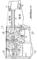
- reference character 10 represents a transmission housing that contains the torque transmitting gear elements. It includes a forward wall 12 and a rearward wall 14. A tailshaft extension housing 16 is secured to the rearward wall 14. Housing 16 includes a forward wall 18 having a flange 20 for accommodating bolts 22 which secure the extension housing 16 to the housing 10. A power output shaft 24 extends through the extension housing 16. It is splined, as shown at 26, to permit a driving connection with an internally splined slip yoke shaft which forms a part of a universal joint connection with a drive shaft that extends to the differential gearing in the vehicle driveline, the output torque of the differential gearing being distributed to the traction wheels for the vehicle. An extension shaft seal assembly 28 is received within a shaft opening 30 in the extension housing for sealing the output shaft 24 and the associated slip yoke assembly not shown in Figure 1.
- the forward wall 12 of the housing 10 is provided with a bearing 32 which receives front bearing 34 for torque input shaft .36.
- a stationary clutch sleeve shaft support 38 is carried by cover plate 40, which is bolted to the front wall 12 over the bearing opening.
- Input shaft 36 is splined at 42 to permit a driving connection with the friction clutch disc of a selectively engageable friction clutch through which torque is delivered from the engine flywheel of an internal combustion engine to the shaft 36.
- the output shaft 24 at its inboard end is journalled by bearing 44 in bearing opening 46 formed in end wall 14.
- the outboard end of the shaft 24 is journalled in bearing 48.
- the output shaft 24 forms a part of and is integrally joined to intermediate shaft 50, which has formed thereon a first bearing portion 52 which journals low speed ratio gear 54, a second bearing portion 56 which journals a second speed ratio gear 58 and a third bearing portion 60 which journals overdrive gear 62.
- the forward end of the intermediate shaft 50 is journalled by bearing 64 in bearing opening 66 formed in torque input gear 68.
- the input shaft 36 forms a part of and is integrally joined to the input gear 68.
- the shaft 36 is sealed by seal element 70 carried in a seal pocket formed in the cover plate 40.
- the upper end of the transmission housing 10 is provided with an access opening 72, which is covered by a stamped sheet metal cover 74 that is bolted in place by appropriately spaced clamping bolts 76 threadably received in the top of the housing 10.
- a transmission countershaft 76 is disposed in the housing 10 and is supported at its forward end in countershaft opening 78 formed in the wall 12. It is supported at its rear end in opening 80 formed in the wall 18.
- Countershaft 76 rotatably supports a cluster gear assembly generally indicated by reference numeral 82 which has formed thereon spaced gear elements 84, 86, 88 and 90.
- the cluster gear assembly 82 is journalled at its rearmost end by bearing 92 on the countershaft 76 and is journalled at its forward end by bearing 94 on the countershaft 76.
- a reverse gear 96 is formed on synchronizer clutch sleeve 98, which is internally splined in sliding relationship on an externally splined synchronizer hub 100 for the 1-2 shift and the 2-1 shift. Hub 100, in turn, is splined at 102 to the intermediate shaft 50.
- Reverse gear 96 is shown in its operative position for reverse drive in Figure 1. This corresponds to the neutral condition for the synchronizer clutch assembly.
- gear 96 When the gear 96 is in the position shown, it engages a reverse drive pinion 104 which is mounted slidably on a reverse pinion support shaft 106. Shaft 106, in turn, is supported at each of its ends in an opening formed in bosses that form a part of the. transmission housing 10.
- Reverse pinion 104 is seen in its edge view in Figure 1 and is seen in its end view in Figure 5.
- Reverse pinion 104 has an extension on which is formed a groove 108.
- the operating end 112 of the fork 110 engages the groove 108.
- the shift fork 110 is supported by shift fork rail 114 which in turn is supported at its rearward end 116 in opening 118 formed in the wall 14 as seen best in Figure 3.
- Shift fork rail 114 is supported at its forward end 120 in opening 122 formed in boss '124, which forms a part of the transmission housing 10.
- the reverse shift fork 110 is pinned to the shift fork rail 114 by pin 126. Also best seen in Figure 3.
- the reverse shift fork 110 is provided with an operating groove 128 seen in Figures 3 and 5. Received in the groove 128 is a pin 130 which is carried in the lower end 132 of relay lever 134, which in turn is pivoted on stub shaft 136. This shaft 136 is formed on the inboard end of bolt 138 received in the threaded opening formed in boss 140 for the transmission housing 10.
- the 1-2 synchronizer clutch sleeve 98 is provided with a shift fork groove 142 for receiving the operating ends 144 and 146 of the 1-2 shift fork 148, as best seen in Figure 5.
- Synchronizer clutch sleeve 98 is formed with internal clutch teeth 150 which are adapted to engage external synchronizer clutch teeth 152 formed on the low speed ratio main gear 54.
- Synchronizer clutch blocker ring 156 is provided with a cone clutch surface that registers with external cone clutch surfaces on the gear 54 in known fashion to establish synchronism in the rotational velocities of the sleeve 98 with respect to the gear 54 prior to a shift to the low speed ratio condition.
- the synchronizer clutch is actuated by the force applied to the ring 156 by synchronizer clutch inserts 158, which are urged in a radially outward direction by a clutch spring 160.
- Blocker ring teeth 166 formed on the blocker ring 156 prevent shifting movement of the sleeve 98 into clutching engagement with the clutch teeth 152 when the motion of the intermediate shaft 50 is out of synchronism with the motion of the gear 54.
- sleeve 98 can be moved to the clutching position to establish low speed ratio. At that time torque is distributed from the input shaft 36 and through the input main gear 68 to the cluster gear element 90. Torque then passes from cluster gear element 84 and through main gear 54 to the intermediate shaft 50 and the output shaft 24.
- Main gear 58 also is adapted to be selectively connected to the intermediate shaft 50 through a synchronizer clutch mechanism identified generally by reference character 68.
- the synchronizer clutch mechanism corresponds to the one described previously with reference to the low speed ratio main gear 54. It is actuated when the sleeve 98 is shifted in a left hand direction as viewed in Figure 1, thereby establishing a second underdrive ratio as the gear 58 is connected to the intermediate shaft 50 and the output shaft 24. Torque is delivered to the gear 58 from the cluster gear element 86 with which is meshes.
- both gears 58 and 54 are disconnected from the intermediate shaft 50 and the associated reverse gear 96 is positioned so that it may be engaged by reverse pinion 104 as the latter is shifted in a left hand direction as viewed in Figure 1.
- the shifting that occurs by means of the shifting mechanism described previously will be discussed with reference to Figure 5.
- a 3-4 synchronizer clutch mechanism is indicated generally by reference character 170. It includes a synchronizer hub 172 that is splined at 174 to the forward end of the intermediate shaft 50.
- the synchronizer assembly 170 includes also a synchronizer clutch sleeve 176, which has internal clutch teeth adapted to register with clutch teeth 178 on gear 62 when the sleeve 176 is moved in a rearward direction and which is adapted to engage clutch teeth 180 on gear 68 when the sleeve 176 is moved in a forward direction.
- a pair of synchronizers similar to the synchronizer described with reference to the gear 54, is provided for each of the gears 62 and 68.
- the sleeve 176 is provided with a shift fork groove 182, which receives the ends of the 3-4 shift fork described with reference to Figure 4.
- the synchronizer clutch sleeve 98 is moved to the neutral position as shown in Figure 1 and the sleeve 176 is moved to a forward direction thereby connecting the input main gear to the intermediate shaft 50.
- a shift to the overdrive high speed ratio is achieved by moving the synchronizer clutch sleeve 176 in a rearward direction whereby input torque is distributed from the input shaft through gear 68, gear elements 90 and 88 and high speed overdrive ratio gears 62, which becomes locked to the intermediate shaft.
- the reverse drive pinion 104 is splined at 184 to the reverse drive pinion shaft.
- Reverse drive pinion 186 is secured or integrally formed with the reverse pinion shaft, and it meshes with the cluster gear element 84.
- the torque delivery path is comprised of input shaft 36, input gear 68, cluster gear element 90, cluster gear element 84, reverse pinion 186, reverse pinion 104 and reverse drive gear 96.
- the 3-4 synchronizer clutch sleeve 176 is shifted by the shift fork 188, seen in Figure 4.
- Fork 188 includes fork ends 190 and 194 adapted to be received in groove 182.
- Fork 188 is supported by fork shaft 196, which is end supported in an opening 198 formed in boss 200 in the housing 10 and in a corresponding opening 202 formed in the forward wall 12 of the housing 10.
- a reversing lever 204 is mounted on pin 206 received in opening 208 formed in the housing 10 as seen in Figure 4.
- the lower end of the reversing lever 204 carries a pin 210, which is engaged in a shift fork groove 212 formed in the shift fork 188.
- a shift rail 214 is slidably supported at its forward end in opening 216 formed in the wall 12 as seen best in Figure 3.
- Rail 214 carries a collar 218, which is formed with a groove 220.
- a pin 222 carried at the upper end of reverse lever 204 registers with groove 220 when the rail 214 is shifted in the direction of its axis.
- the clutch sleeve 176 is shifted in a right hand direction as seen in Figure 1. This establishes an overdrive condition.
- the shift fork 148 is supported slidably by the shift rail 214.
- the shift fork 148 includes a collar 224 which carries a foot 226, as best seen in Figure 2. This foot has a slot 228 that is adapted to receive a pin 230 when the pin is moved into registry with it.
- the foot 232 overlies the foot 226, as seen in Figure 2 as well as in Figure 3.
- the foot 232 is formed with a slot 234 that is adapted to register with the pin 230 when it is aligned with it.
- the pin 230 is secured or fixed to the collar 236, which is pinned or otherwise fixed to the shift rail 214.
- An interlock plate 238 surrounds the shift rail 214: It is loosely mounted on the shift rail 214, and it includes a slot 240 through which the pin 230 extends. As the pin 230 rotates about the axis of the shift rail 214 upon rotation of the shift rail 214, the interlock plate 238 also is caused to rotate. It is held fast against movement in a fore-and-aft direction by a slot 242 formed in the transmission case 10, as seen best in Figure 3. The outline of the interlock plate 238 is best seen in Figure 5. It is shown in an end view in Figure 3.
- the synchronizer fork collar 224 includes a foot 226 which is adapted to receive pin 230 in a slot 228 when the pin is in the position shown in Figure 5. At that time the pin will move the shift fork 148 in a fore-and-aft direction as the shift rail 214 is moved fore-and-aft because the collar 224 on the shift fork 148 becomes locked to the rail 214 by the pin in the registering slot 228 in the foot 226. If the pin 230 is rotated in a clockwise direction as seen in Figure 5, it is adapted to register with a slot 246 formed in the foot 232.
- Axial movement of the shift rail 214 then will cause shifting movement of the collar 218 in a fore-and-aft direction, thus actuating the shift fork 188.
- Movement of the pin 230 is a counterclockwise direction as seen in Figure 5 will cause it to register with a slot 248 formed in the relay lever 134.
- the reverse shift fork 110 is actuated.
- the interlock plate 238 registers with the slots 228 and 248, thus locking the shift forks 110 and 148 during shifting movement of the shift fork 188 (not shown).
- the interlock plate 238 locks the relay lever 134 and the shift fork 188 when the pin is moved to the position shown in Figure 5. If the pin 230 is moved in a counterclockwise direction to cause it to engage the relay lever 134, the shift fork 148 and the shift fork 188 become locked by the interlock plate 238.
- the rotary motion of the shift rail- 214 and the axial shifting movement of the shift rail 214 is accomplished by the shift cane assembly shown in the right hand side of the assembly of Figure 1 and in Figures.6 and 7.
- the shift cane which is shown at 250, is formed with a generally semi-spherical bearing 252 which registers with a hold-down plate 254 which is provided with a registering internal spherical surface.
- the plate 254 is bolted to a side mounted cane housing 256, which has an opening 258 through which the cane 250 is received.
- a nylon bearing is generally spherical form surrounds the bearing 252 as seen at 260.
- the cane housing 256 is provided with flanges 262 and 264 which are bolted to the side of the tailshaft extension housing 16 by suitable clamping bolts 266 and 268, respectively.
- the base of the cane 250 carries a pair of fork parts 270 which straddle the offset shift lever portion 272.
- Shift lever portion 272 carries a pair of stops 274 and 276 situated fore-and-aft of the forked parts 270.
- the offset shift rail portion 272 is joined to the shift rail 214 by arm 278, thereby defining a crank as best seen in Figure 1.
- the shift rail 214 will be rotated about its axis. It is apparent also that if the cane 250 is oscillated in a plane parallel to the plane of the section of Figure 1, the shift rail 214 will be moved fore-and-aft in the direction of its axis.
- the cane is capable of imparting a compound motion to the shift rail 214.
- the cane 250 is slidably received in a central opening 280 formed in the bearing 252.
- a spring seat 281 surrounding the cane 250 supports a spring 283 resting against the stamping 254, thus normally urging the cane in an upward direction as seen in Figure 1. If the cane 250 is pressed in a downward direction i.e. transverse to the axis of the shift rail 214 as seen in Figure 1, a shoulder 284 formed on one side of the base of the cane 250 will be moved until it is below the edge 286 of a stop 288 that is fixed to the housing 256 thereby permitting movement of the cane perpendicular to the plane of Figure 1 until the stop contacts the cane which movement causes the shift rail 214 to rotate in a reverse drive position.
- the stop can be seen in both Figure 1 and Figure 6. It is held in a boss 290, which is formed on the interior of the housing 256. When in the upwardly biased position, a first part of the shift cane, namely the shoulder 284, contacts the stop 288, as shown in Figure 6, and movement of the cane 250 tending to rotate the shift rail 214 is prevented.
- the cap that normally would close the end of the housing 256 is not shown in Figure 6 so that the interior of the housing can be seen.
- the cap is shown in Figure 1 and is identified by reference character 292. It is adapted to carry a reversing light switch 296 that is engaged by the boss or stop 274 on the offset portion 272 on the shift rail when the shift rail is moved to the reverse position.
- a dust cover sleeve shaft 298 surrounds the shift rail 214.
- One end of the dust cover 298 is received within an opening 300 in the end wall 18 of extension housing 16, and the other end of the dust cover is received within an opening 302 in the end of the housing 256.
Landscapes
- Engineering & Computer Science (AREA)
- General Engineering & Computer Science (AREA)
- Mechanical Engineering (AREA)
- Gear-Shifting Mechanisms (AREA)
Claims (1)
- Mécanisme de transmission à plusieurs rapports à commande manuelle comprenant un arbre d'entrée (36), un arbre de sortie (24) et un arbre intermédiaire (50) disposés coaxiale- ment, l'arbre intermédiaire (50) étant relié à l'arbre de sortie, un carter (10) de boite de vitesses un prolongement (16) de carter entourant l'arbre de sortie, un pignon d'entrée (68) relié audit arbre d'entrée, un premier et un second pignons (54, 58) de rapports intermédiaires et un pignon (62) de rapport surmultiplié montés rotatifs sur l'arbre intermédiaire, un premier dispositif (98) d'accouplement et de synchronisation sur l'arbre intermédiaire pour relier sélectivement le premier ou le second pignon de rapports intermédiaires à l'arbre intermédiaire, un second dispositif (170) d'accouplement et de synchronisation relié à l'arbre intermédiaire pour relier sélectivement le pignon d'entrée ou le pignon de rapport surmultiplié à l'arbre intermédiaire, un ensemble (82) d'engrenages à dentures étagées parallèle à l'axe de l'arbre intermédiaire et comprenant des pignons (90, 88, 86, 84) qui sont engagés respectivement en prise avec le pignon d'entrée et le pignon de rapport surmultiplié et avec chacun des pignons de rapports intermédiaires, un pignon (104) de marche arrière monté rotatif autour d'un second axe parallèle à l'axe de l'arbre intermédiaire et pouvant être engagé en prise avec l'un des pignons de l'ensemble de pignons à denture étagées, un arbre de commande (214) s'étendant dans la direction de l'axe de l'arbre intermédiaire, un doigt (230) de sélection porté par l'arbre de commande, une première fourchette (148) de changement de rapport montée coulissante sur l'arbre de commande; le premier dispositif d'accouplement et de synchronisation comprenant un manchon (98) d'accouplement et de synchronisation actionné par la fourchette (148) de changement de rapport, un premier collier (224) porté par la fourchette (148) de changement de rapport, un second collier (218) monté coulissant sur l'arbre de commande, chaque collier ayant un prolongement (226, 232) respectivement, présentant des cavités (228, 234) adaptées pour être attaquées par le doigt sélecteur (230) de l'arbre de commande, sélectivement, à la suite d'un mouvement de rotation de l'arbre de commande pour venir coïncider avec les cavités en reliant ainsi les colliers à l'arbre de commande, une seconde fourchette (188) de changement de rapport pouvant venir en prise avec le second dispositif (178) d'accouplement et de synchronisation et montée de façon à coulisser sur un axe parallèle à l'axe de l'arbre de commande, et un levier (204) d'inversion reliant le second collier à la seconde fourchette (188) de changement de rapport, grâce à quoi cette seconde fourchette est déplacée dans une direction à la suite du déplacement de l'arbre de commande dans la direction opposée, mécanisme caractérisé en ce qu'il comprend un boîtier (256) de levier de changement de rapport fixé sur le prolongement (16) de carter au moyen de brides (262, 264) fixées sur le côté dudit prolongement au moyen de vis (266, 268), l'extrêmité arrière de l'arbre (214) de commande comportant une partie (272) décalée formant un arbre ayant un axe parallèle à celui de l'arbre (214), un levier (250) de changement de rapport articulé de façon universelle dans le boitier (256), le levier (250) s'étendant à peu près verticalement et ayant une partie suspendue formant des branches (270) d'une fourche qui chevauchent la partie décalée et sont en contact avec des butées (274, 276) de cette partie (272), grâce à quoi l'arbre (214) de commande est déplacé dans la direction de son axe à la suite de la rotation du levier dans un premier plan d'oscillation, l'arbre de commande (214) étant entraîné en rotation à la suite de l'oscillation du levier dans un second plan d'oscillation perpendiculaire au premier plan d'oscillation et de sorte que des butées (288) limitent l'étendue du mouvement dudit levier (250) dans ledit second plan d'oscillation lorsque les butées (288) entrent en contact avec une première partie (284) du levier (250) de changement de rapport, celui-ci pouvant être déplacé transversalement à la direction de l'axe de l'arbre de commande (214) pour empêcher toute interférence entre la butée (288) et ladite première partie (284) du levier de changement de rapport, grâce à quoi l'étendue du déplacement angulaire du levier de changement de rapport dans le second plan d'oscillation dans une direction est augmentée, permettant ainsi à l'arbre de commande de prendre une position de marche arrière.
Applications Claiming Priority (2)
| Application Number | Priority Date | Filing Date | Title |
|---|---|---|---|
| US05/889,686 US4222281A (en) | 1978-03-24 | 1978-03-24 | Single shift rail manual transmission with overdrive speed ratio |
| US889686 | 1978-03-24 |
Publications (3)
| Publication Number | Publication Date |
|---|---|
| EP0004361A2 EP0004361A2 (fr) | 1979-10-03 |
| EP0004361A3 EP0004361A3 (en) | 1979-10-31 |
| EP0004361B1 true EP0004361B1 (fr) | 1983-02-09 |
Family
ID=25395596
Family Applications (1)
| Application Number | Title | Priority Date | Filing Date |
|---|---|---|---|
| EP79100821A Expired EP0004361B1 (fr) | 1978-03-24 | 1979-03-17 | Transmission à commande manuelle avec un arbre de commande unique et à rapport de vitesses surmultiplié |
Country Status (4)
| Country | Link |
|---|---|
| US (1) | US4222281A (fr) |
| EP (1) | EP0004361B1 (fr) |
| CA (1) | CA1112077A (fr) |
| DE (1) | DE2964689D1 (fr) |
Cited By (1)
| Publication number | Priority date | Publication date | Assignee | Title |
|---|---|---|---|---|
| DE102007013929A1 (de) * | 2007-03-23 | 2008-09-25 | Zf Friedrichshafen Ag | Anordnung einer Schaltschwinge in einem Getriebe |
Families Citing this family (22)
| Publication number | Priority date | Publication date | Assignee | Title |
|---|---|---|---|---|
| DE3001935C2 (de) * | 1980-01-21 | 1982-09-16 | Ford-Werke Ag, 5000 Koeln | Schaltvorrichtung für ein Wechselgetriebe |
| US4307624A (en) * | 1980-02-27 | 1981-12-29 | Ford Motor Company | Transmission gear selector arm and sleeves for shifting forks |
| US4377093A (en) * | 1980-03-03 | 1983-03-22 | Ford Motor Company | Shift mechanism for a five speed transaxle transmission |
| JPS57137750A (en) * | 1981-02-20 | 1982-08-25 | Nissan Motor Co Ltd | Operator for change gear |
| JPS57190163A (en) * | 1981-05-19 | 1982-11-22 | Nissan Motor Co Ltd | Preventive mechanism of gear disengagement |
| US4799399A (en) * | 1981-09-08 | 1989-01-24 | Ford Motor Company | Manually controlled multiple speed ratio transmission |
| DE3146614C2 (de) * | 1981-11-25 | 1984-08-30 | Ford-Werke AG, 5000 Köln | Schalteinrichtung für ein Wechselgetriebe in Vorlegebauweise, insbesondere für Kraftfahrzeuge |
| NL8101633A (nl) * | 1982-04-19 | 1982-11-01 | Dana Corp | Versnellingsbak. |
| US4515031A (en) * | 1982-09-28 | 1985-05-07 | Ford Motor Company | Chain driven reverse gear for a manual transmission |
| DE3314411A1 (de) * | 1983-04-21 | 1984-10-25 | Dr.Ing.H.C. F. Porsche Ag, 7000 Stuttgart | Kraftfahrzeuggetriebe |
| US4532823A (en) * | 1983-10-06 | 1985-08-06 | Chrysler Corporation | Concentric shift rail mechanism |
| DE4402443A1 (de) * | 1993-01-27 | 1994-07-28 | Mazda Motor | Schalteinrichtung für Handschaltgetriebe |
| US5363715A (en) * | 1993-06-28 | 1994-11-15 | Eaton Corporation | Transmission X-control mechanism and pivot pin therefore |
| US5562011A (en) * | 1995-04-06 | 1996-10-08 | Ford Motor Company | Cam actuated single rail manual transmission |
| US6000294A (en) | 1997-11-15 | 1999-12-14 | Eaton Corporation | System and method for fluid assisted shifting of mechanical transmissions |
| DE19753728A1 (de) * | 1997-12-04 | 1999-06-10 | Zahnradfabrik Friedrichshafen | 12-Gang-Getriebe für Nutzfahrzeuge |
| US6035738A (en) * | 1998-03-17 | 2000-03-14 | Eaton Corporation | Bias mechanism for single shift shaft mechanical transmissions |
| US6082215A (en) * | 1998-08-28 | 2000-07-04 | Zf Meritor | Single rail top cover assembly |
| US7080566B2 (en) * | 2004-03-18 | 2006-07-25 | Ford Global Technologies, Llc | Ranged single clutch layshaft powershift automatic transmission |
| US7044014B2 (en) * | 2004-05-25 | 2006-05-16 | Ford Global Technologies, Llc | Dual clutch automatic transaxle |
| ITBO20090516A1 (it) * | 2009-07-31 | 2011-02-01 | Cima | Scatola del cambio per autoveicoli. |
| US8726749B2 (en) * | 2011-09-25 | 2014-05-20 | Eaton Corporation | Transmission overdrive yoke position sensor for range trigger |
Family Cites Families (20)
| Publication number | Priority date | Publication date | Assignee | Title |
|---|---|---|---|---|
| GB1053353A (fr) * | 1900-01-01 | |||
| US1973553A (en) * | 1929-11-21 | 1934-09-11 | Austin Herbert | Change speed gear for use more especially with motor road vehicles |
| US1980644A (en) * | 1931-06-29 | 1934-11-13 | White Motor Co | Gear shifting mechanism |
| US2055770A (en) * | 1934-09-22 | 1936-09-29 | Int Motor Co | Five-speed vehicle transmission |
| FR999854A (fr) * | 1946-01-17 | 1952-02-05 | Applic Ind Et Commerciales Int | Boîte de vitesses à synchroniseurs |
| FR81237E (fr) * | 1961-07-10 | 1963-12-06 | ||
| DE1286859B (de) * | 1963-04-11 | 1969-01-09 | Vauxhall Motors Ltd | Schalteinrichtung fuer Zahnraederwechselgetriebe |
| US3202005A (en) * | 1963-08-22 | 1965-08-24 | Ford Motor Co | Multiple speed ratio power transmission mechanism with fully synchronized speed ratio shifts |
| GB1038591A (en) * | 1964-03-19 | 1966-08-10 | Vauxhall Motors Ltd | Motor vehicle gear selector mechanisms |
| GB1008556A (en) * | 1964-07-22 | 1965-10-27 | Ford Motor Co | Assembly of gearbox, driveshaft and gear shift mechanism |
| GB1056206A (en) * | 1965-07-16 | 1967-01-25 | Ford Motor Co | Gearbox selector mechanism |
| GB1195167A (en) * | 1968-05-28 | 1970-06-17 | Rootes Motors Ltd | Improvements in or relating to Gear Box Units. |
| GB1195939A (en) * | 1968-08-29 | 1970-06-24 | Vauxhall Motors Ltd | Selector Mechanisms for Change-Speed Gears. |
| GB1224832A (en) * | 1969-01-28 | 1971-03-10 | British Motor Corp Ltd | Gear selector mechanism |
| GB1274334A (en) * | 1970-03-07 | 1972-05-17 | British Leyland Austin Morris | Gear selection mechanism |
| US3935752A (en) * | 1974-02-11 | 1976-02-03 | Borg-Warner Corporation | Transmission |
| US3916718A (en) * | 1974-02-11 | 1975-11-04 | Borg Warner | Transmission control |
| US3929029A (en) * | 1974-02-25 | 1975-12-30 | Borg Warner | Transmission shift control linkage |
| US3962930A (en) * | 1974-12-16 | 1976-06-15 | Ford Motor Company | Synchronized manually controlled multiple speed ratio transmission |
| JPS51114555A (en) * | 1975-04-02 | 1976-10-08 | Toyota Motor Corp | Speed change gear |
-
1978
- 1978-03-24 US US05/889,686 patent/US4222281A/en not_active Expired - Lifetime
-
1979
- 1979-03-17 EP EP79100821A patent/EP0004361B1/fr not_active Expired
- 1979-03-17 DE DE7979100821T patent/DE2964689D1/de not_active Expired
- 1979-03-20 CA CA323,825A patent/CA1112077A/fr not_active Expired
Cited By (1)
| Publication number | Priority date | Publication date | Assignee | Title |
|---|---|---|---|---|
| DE102007013929A1 (de) * | 2007-03-23 | 2008-09-25 | Zf Friedrichshafen Ag | Anordnung einer Schaltschwinge in einem Getriebe |
Also Published As
| Publication number | Publication date |
|---|---|
| CA1112077A (fr) | 1981-11-10 |
| EP0004361A3 (en) | 1979-10-31 |
| US4222281A (en) | 1980-09-16 |
| DE2964689D1 (en) | 1983-03-17 |
| EP0004361A2 (fr) | 1979-10-03 |
Similar Documents
| Publication | Publication Date | Title |
|---|---|---|
| EP0004361B1 (fr) | Transmission à commande manuelle avec un arbre de commande unique et à rapport de vitesses surmultiplié | |
| US4377093A (en) | Shift mechanism for a five speed transaxle transmission | |
| US3962930A (en) | Synchronized manually controlled multiple speed ratio transmission | |
| US4290318A (en) | Operating mechanism of a transfer unit | |
| US4170273A (en) | Transmission apparatus for four-wheel drive motor vehicle | |
| US4307624A (en) | Transmission gear selector arm and sleeves for shifting forks | |
| US4356879A (en) | Manipulation device for a transmission apparatus | |
| US4704917A (en) | Transfer system for vehicles | |
| US4089394A (en) | Park lock and gear shift for a vehicle transmission | |
| JPH05141488A (ja) | 一定かみ合い伝動装置 | |
| US4690015A (en) | Power transfer device for automotive vehicles | |
| US4581950A (en) | Gear changing device | |
| US5309782A (en) | Multiple ratio manual transmission | |
| SE436994B (sv) | Transmission for motorfordon der motorn er lengsstellt monterad framfor framaxeln | |
| GB2093542A (en) | Vehicle parking brake system | |
| US2633753A (en) | Transmission | |
| US3247937A (en) | Synchronizer clutch assembly | |
| US4483213A (en) | Select detent mechanism of an automotive manual transmission | |
| US2993574A (en) | Anti-inertia brake for countershaft power transmission | |
| US3491862A (en) | Transmission ratio control mechanism for a tractor driveline | |
| GB2146714A (en) | Four-wheel drive axleshaft clutch mechanism | |
| US5291799A (en) | Unitary ratio selector mechanism for a multiple ratio manual transmission | |
| US4151902A (en) | Parking brake mechanism for motor vehicle equipped with power transmission with torque converter | |
| US3486392A (en) | Shift interlock lever system for controlling ratio changes in a manually controlled transmission | |
| US5016488A (en) | Shift mechanism for engaging sliding gear in manual transmission |
Legal Events
| Date | Code | Title | Description |
|---|---|---|---|
| PUAI | Public reference made under article 153(3) epc to a published international application that has entered the european phase |
Free format text: ORIGINAL CODE: 0009012 |
|
| PUAL | Search report despatched |
Free format text: ORIGINAL CODE: 0009013 |
|
| AK | Designated contracting states |
Designated state(s): DE FR GB |
|
| AK | Designated contracting states |
Designated state(s): DE FR GB |
|
| 17P | Request for examination filed | ||
| GRAA | (expected) grant |
Free format text: ORIGINAL CODE: 0009210 |
|
| AK | Designated contracting states |
Designated state(s): DE FR GB |
|
| REF | Corresponds to: |
Ref document number: 2964689 Country of ref document: DE Date of ref document: 19830317 |
|
| ET | Fr: translation filed | ||
| REG | Reference to a national code |
Ref country code: GB Ref legal event code: 746 |
|
| REG | Reference to a national code |
Ref country code: FR Ref legal event code: DL |
|
| PGFP | Annual fee paid to national office [announced via postgrant information from national office to epo] |
Ref country code: GB Payment date: 19910225 Year of fee payment: 13 |
|
| PGFP | Annual fee paid to national office [announced via postgrant information from national office to epo] |
Ref country code: DE Payment date: 19910315 Year of fee payment: 13 |
|
| PGFP | Annual fee paid to national office [announced via postgrant information from national office to epo] |
Ref country code: FR Payment date: 19910329 Year of fee payment: 13 |
|
| PG25 | Lapsed in a contracting state [announced via postgrant information from national office to epo] |
Ref country code: DE Effective date: 19920214 |
|
| PG25 | Lapsed in a contracting state [announced via postgrant information from national office to epo] |
Ref country code: GB Effective date: 19920317 |
|
| GBPC | Gb: european patent ceased through non-payment of renewal fee | ||
| PG25 | Lapsed in a contracting state [announced via postgrant information from national office to epo] |
Ref country code: FR Effective date: 19921130 |
|
| REG | Reference to a national code |
Ref country code: FR Ref legal event code: ST |
|
| PLBE | No opposition filed within time limit |
Free format text: ORIGINAL CODE: 0009261 |
|
| STAA | Information on the status of an ep patent application or granted ep patent |
Free format text: STATUS: NO OPPOSITION FILED WITHIN TIME LIMIT |