EP0004539A2 - Hochlast-Drahtwiderstand - Google Patents
Hochlast-Drahtwiderstand Download PDFInfo
- Publication number
- EP0004539A2 EP0004539A2 EP79100262A EP79100262A EP0004539A2 EP 0004539 A2 EP0004539 A2 EP 0004539A2 EP 79100262 A EP79100262 A EP 79100262A EP 79100262 A EP79100262 A EP 79100262A EP 0004539 A2 EP0004539 A2 EP 0004539A2
- Authority
- EP
- European Patent Office
- Prior art keywords
- wire
- resistor
- connecting wire
- fuse
- ceramic housing
- Prior art date
- Legal status (The legal status is an assumption and is not a legal conclusion. Google has not performed a legal analysis and makes no representation as to the accuracy of the status listed.)
- Withdrawn
Links
Images
Classifications
-
- H—ELECTRICITY
- H01—ELECTRIC ELEMENTS
- H01H—ELECTRIC SWITCHES; RELAYS; SELECTORS; EMERGENCY PROTECTIVE DEVICES
- H01H85/00—Protective devices in which the current flows through a part of fusible material and this current is interrupted by displacement of the fusible material when this current becomes excessive
- H01H85/02—Details
- H01H85/04—Fuses, i.e. expendable parts of the protective device, e.g. cartridges
- H01H85/041—Fuses, i.e. expendable parts of the protective device, e.g. cartridges characterised by the type
- H01H85/044—General constructions or structure of low voltage fuses, i.e. below 1000 V, or of fuses where the applicable voltage is not specified
-
- H—ELECTRICITY
- H01—ELECTRIC ELEMENTS
- H01C—RESISTORS
- H01C1/00—Details
- H01C1/02—Housing; Enclosing; Embedding; Filling the housing or enclosure
-
- H—ELECTRICITY
- H01—ELECTRIC ELEMENTS
- H01C—RESISTORS
- H01C1/00—Details
- H01C1/14—Terminals or tapping points specially adapted for resistors; Arrangements of terminals or tapping points on resistors
-
- H—ELECTRICITY
- H01—ELECTRIC ELEMENTS
- H01C—RESISTORS
- H01C1/00—Details
- H01C1/14—Terminals or tapping points specially adapted for resistors; Arrangements of terminals or tapping points on resistors
- H01C1/144—Terminals or tapping points specially adapted for resistors; Arrangements of terminals or tapping points on resistors the terminals or tapping points being welded or soldered
-
- H—ELECTRICITY
- H01—ELECTRIC ELEMENTS
- H01C—RESISTORS
- H01C3/00—Non-adjustable metal resistors made of wire or ribbon, e.g. coiled, woven or formed as grids
- H01C3/14—Non-adjustable metal resistors made of wire or ribbon, e.g. coiled, woven or formed as grids the resistive element being formed in two or more coils or loops continuously wound as a spiral, helical or toroidal winding
- H01C3/20—Non-adjustable metal resistors made of wire or ribbon, e.g. coiled, woven or formed as grids the resistive element being formed in two or more coils or loops continuously wound as a spiral, helical or toroidal winding wound on cylindrical or prismatic base
-
- H—ELECTRICITY
- H01—ELECTRIC ELEMENTS
- H01H—ELECTRIC SWITCHES; RELAYS; SELECTORS; EMERGENCY PROTECTIVE DEVICES
- H01H85/00—Protective devices in which the current flows through a part of fusible material and this current is interrupted by displacement of the fusible material when this current becomes excessive
- H01H85/02—Details
- H01H85/04—Fuses, i.e. expendable parts of the protective device, e.g. cartridges
- H01H85/041—Fuses, i.e. expendable parts of the protective device, e.g. cartridges characterised by the type
- H01H85/048—Fuse resistors
Definitions
- High-load wire resistor in which a wire resistor element is inserted in a through hole in a ceramic housing and a connecting wire is fed back into the area of the other connecting wire via a fuse, characterized in that the ceramic housing (1) has an eccentric through hole (3) in a known manner , through which a connecting wire (6) is returned and the returned connecting wire (6) consists of an alloy melting from 623 ° K.
- the invention relates to a high-load wire resistor, in which a wire resistor element is inserted in a through bore of a ceramic housing and a connection is fed back into the area of the other connection via a fuse.
- a current limiter is connected in series with the resistor, which ensures a current interruption from a certain current value.
- fuses or current limiters must be assigned to different resistance values.
- the high-load wire resistance mentioned at the beginning falls under the second case.
- a solder joint is provided, which melts when the temperature of the resistor exceeds a predetermined value for a predetermined time.
- the spring-like retaining bracket separates by snapping back into its rest position, so that the electrical connection is interrupted.
- This known resistor can be seen as an advantage that after the "thermal fuse" has responded, a connection can be re-established by re-soldering the connecting wire and the retaining bracket.
- strict safety regulations no longer permit repairable fuses through soldering, because this could lead to the use of solder alloys that melt at a higher temperature than intended.
- the invention is based on the object of specifying a high-load wire resistor whose fuse responds reliably, but makes repair very difficult or even impossible.
- the ceramic housing has an eccentric bore in a known manner, through which a connecting wire is returned and the returned connecting wire consists of an alloy melting from 623 o K.
- High-load wire resistors with a wire resistance element arranged in a through-hole in a ceramic housing, in which a connecting wire is returned through an eccentric hole in the ceramic housing, are known in principle (DE-PS 1 465 416). A backup by current or temperature limitation is not provided.
- the returned connecting wire is chosen as a "fuse", which, however, does not limit the current, but responds to the temperature in the ceramic housing.
- the lead wire that is returned also heats up. If the temperature exceeds a predetermined limit, the returned connecting wire also reaches its highest temperature and melts.
- the highest temperature hot spot
- the connecting wire suddenly melts over a certain distance, the length of the distance depending on the point in time at which the temperature falls below the limit.
- the returned connecting wire remains rigid above and below the melting path. Therefore, no molten material falls on the board. The resistance therefore does not lose one of its two pillars and remains remain stable.
- the described function of the resistor according to the invention is not critical with regard to the wire diameter.
- the fuse function is slow, which is always desirable for high-load wire resistors. Short-term pulse-like overloads should not immediately lead to a failure of the resistance.
- An essentially cuboidal elongated ceramic housing 1 has a central through-hole 2 and four eccentric through-holes 3 of smaller diameter, which are arranged in the corner areas and whose axes run parallel to the axis of the central through-hole 2.
- wedge-shaped grooves 4 are formed in the long sides of the ceramic housing. However, they are of no importance for the invention.
- the through hole 2 receives a wire resistance element 7, which is of a known type and should therefore not be described in detail.
- the wire resistance element 7 has two connecting wires 5 and 6, the connecting wire 6 being fed back parallel to the connecting wire 5 via one of the eccentric bores 3.
- the lead wire 6 is formed of a from 623 0 K-melting alloy. Since the highest temperature in the ceramic housing arises to about two thirds of the height of the housing 1 (seen in the drawing from the end face shown), it is ensured that in the event of an overload Melting of the connecting wire 6 always takes place within the eccentric through-hole 3.
- the accommodation of the fuse within the ceramic housing has the additional advantage that temperature influence by the environment, for example by differently strong and differently warm air currents or the like, is almost eliminated.
- the connecting wire 6 thus responds essentially only to the temperature which is developed by the wire resistance element 7 itself.
Landscapes
- Engineering & Computer Science (AREA)
- Microelectronics & Electronic Packaging (AREA)
- Fuses (AREA)
- Measuring Volume Flow (AREA)
Abstract
Hochlastdrahtwiderstand, bei dem der durch eine au- ßermttige Bohrung des Keramikgehäuses zurückgeführte Anschlußdraht als Sicherung wirkt. Die Sicherung wirkt dabei als Temperaturbegrenzung, d.h. der Stromfluß wird unterbrochen, wenn die Temperatur des Widerstands einen Grenzwert überschreitet.
Description
- Hochlast-Drahtwiderstand, bei dem ein Drahtwiderstandselement in einer durchgehenden Bohrung eines Keramikgehäuses eingesetzt ist und ein Anschlußdraht über eine Schmelzsicherung in den Bereich des anderen Anschlußdrahtes zurückgeführt ist, dadurch gekennzeichnet, daß das Keramikgehäuse (1) in bekannter Weise eine außermittige Durchbohrung (3) aufweist, durch die ein Anschlußdraht (6) zurückgeführt ist und der zurückgeführte Anschlußdraht (6) aus einer ab 623°K schmelzenden Legierung besteht.
- Die Erfindung bezieht sich auf einen Hochlast-Drahtwiderstand, bei dem ein Drahtwiderstandselement in einer durchgehenden Bohrung eines Keramikgehäuses eingesetzt ist und ein Anschluß über eine Schmelzsicherung in den Bereich des anderen Anschlusses zurückgeführt ist.
- Ein Drahtwiderstand hoher Belastbarkeit, d.h. ein Widerstand, der für verhältnismäßig hohe Temperaturen ausgelegt ist, kann für elektrische Schaltungen eine Gefahr bedeuten, wenn es bei der Überlastung zu einem Temperaturanstieg kommt, bei dem zulässige Werte überschritten werden. Eine Sicherung gegen Überlast ist auf zweifache Weise möglich:
- Strombegrenzung oder
- Temperaturbegrenzung.
- Im ersteren Fall wird mit dem Widerstand ein Strombegrenzer in Reihe geschaltet, der ab einem bestimmten Stromwert für eine Stromunterbrechung sorgt. Nachteilig ist jedoch, daß unterschiedlichen Widerstandwerten unterschiedliche Sicherungen bzw. Strombegrenzer zugeordnet sein müssen.
- Unter den zweiten Fall fällt der eingangs genannte Hochlast-Drahtwiderstand. Bei diesem ist zwischen einem Anachlußdrahtende und einem als Feder ausgebildeten Haltebügel eine Lötstelle vorgesehen, die schmilzt, wenn die Temperatur des Widerstands einen vorgegebenen Wert eine vorgegebene Zeit überschreitet. Mit dem Schmelzen der Lötstelle trennt sich der federartige Haltebügel durch Zurückschnellen in seine Ruhelage, so daß die elektrische Verbindung unterbrochen wird. Zwar kann bei diesem bekannten Widerstand als Vorteil angesehen werden, daß nach dem Ansprechen der "Thermosicherung" eine Verbindung wider hergestellt werden kann durch erneutes Zusammenlöten von Anschlußdraht und Haltebügel. Strenge Sicherheitsvorschriften lassen jedoch durch Löten reparable Sicherungen nicht mehr zu, weil hierdurch Schmelzlotlegierungen eingesetzt werden könnten, die bei einer höheren Temperatur als vorgesehen schmelzen.
- Der Erfindung liegt die Aufgabe zugrunde, einen Hochlast- Drahtwiderstand anzugeben, dessen Schmelzsicherung zuverlässig anspricht, eine Reparatur jedoch stark erschwert oder gar unmöglich macht.
- Diese Aufgabe wird erfindungsgemäß dadurch gelöst, daß das Keramikgehäuse in bekannter Weise eine außermittige Bohrung aufweist, durch die ein Anschlußdraht zurückgeführt ist und der zurückgeführte Anschlußdraht aus einer ab 623oK schmelzenden Legierung besteht.
- Hochlast-Drahtwiderstände mit einem in einer Durchbohrung eines Keramikgehäuses angeordneten Drahtwiderstandselement, bei denen ein Anschlußdraht durch eine außermittige Bohrung des Keramikgehäuses zurückgeführt ist, sind im Prinzip bekannt (DE-PS 1 465 416). Eine Sicherung durch Strom- oder Temperaturbegrenzung ist jedoch nicht vorgesehen.
- Bei dem erfindungsgemäßen Hochlastdrahtwiderstand wird der zurückgeführte Anschlußdraht als "Sicherung" gewählt, welche jedoch nicht eine Strombegrenzung bewirkt, sondern auf die Temperatur im Keramikgehäuse anspricht. Bei einer Erwärmung des Drahtwiderstandselements erwärmt sich auch der zurückgeführte Anschlußdraht. Überschreitet die Temperatur eine vorgegebene Grenze, erreicht auch der zurückgeführte Anschlußdraht seine höchste Temperatur und schmilzt. Erfahrungsgemäß tritt die höchste Temperatur (hot spot) auf etwa zwei Drittel der Höhe des Widerstandes auf. Bei richtiger Auswahl der Legierung mit dem richtigen Schmelztrajekt schmilzt der Anschlußdraht plötzlich über eine gewisse Strecke, wobei die Länge der Strecke abhängig ist von dem Zeitpunkt, an dem die Grenztemperatur unterschritten wird. Über und unter der Schmelzstrecke bleibt der zurückgeführte Anschlußdraht weiterhin starr. Daher fällt auch kein geschmolzenes Material auf die Platine. Der Widerstand verliert daher auch nicht eines seiner beiden Standbeine und bleibt weiterhin stabil stehen.
- Aufgrund der in die außermittige Bohrung eingebauten Sicherung bleibt dem Benutzer nichts anderes übrig als den Widerstand auszubauen und durch einen neuen zu ersetzen, wenn es zu einem Ansprechen der Sicherung gekommen ist.
- Da es sich, wie erwähnt, nicht um eine Stromsicherung handelt, ist die beschriebene Funktion des erfindungsgemäßen Widerstandes unkritisch in bezug auf den Drahtdurchmesser. Außerdem ist die Sicherungsfunktion träge, was bei Hochlast-Drahtwiderständen stets erwünscht ist. Kurzzeitige impulsartige Überlastungen sollen nicht sofort zu einem Ausfall des Widerstandes führen.
- Ein Ausführungsbeispiel der Erfindung wird nachfolgend anhand von Zeichnungen näher beschrieben.
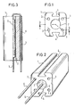
- Fig. 1 zeigt die Ansicht einer Stirnseite eines Keramikgehäuses für einen erfindungsgemäßen Hochlast-Drahtwiderstand.
- Fig. 2 zeigt perspektivisch einen Teil des erfindungsgemäßen Drahtwiderstandes.
- Fig. 3 zeigt einen Schnitt durch den Widerstand nach Fig. 1 entlang 3-3.
- Ein im wesentlichen quaderförmiges längliches Keramikgehäuse 1 besitzt eine mittige Durchbohrung 2 und vier außermittige Durchbohrungen 3 kleineren Durchmessers, die in den Eckbereichen angeordnet sind und deren Achsen im übrigen parallel zur Achse der mittigen Durchbohrung 2 verlaufen. An zwei gegenüberliegenden Seiten sind keilförmige Nuten 4 in die Längsseiten des Keramikgehäuses eingeformt. Für die Erfindung sind sie jedoch ohne Bedeutung.
- Die Durchbohrung 2 nimmt ein Drahtwiderstandselement 7 auf, das von bekannter Bauart ist und deshalb nicht näher beschrieben sein soll.
- Das Drahtwiderstandselement 7 besitzt zwei Anschlußdrähte 5 und 6, wobei der Anschlußdraht 6 über eine der außermittigen Bohrungen 3 parallel zum Anschlußdraht 5 zurückgeführt ist. Erfindungsgemäß ist der Anschlußdraht 6 aus einer ab 6230K schmelzenden Legierung gebildet. Da die höchste Temperatur im Keramikgehäuse etwa auf zwei Drittel der Höhe des Gehäuses 1 entsteht (in der Zeichnung von der gezeigten Stirnfläche aus gesehen), ist sichergestellt, daß im Falle der Überlastung ein Schmelzen des Anschlußdrahtes 6 stets innerhalb der außermittigen Durchbohrung 3 stattfindet.
- Die Unterbringung der Sicherung innerhalb des Keramikgehäuses hat im übrigen den Vorteil, daß eine Temperaturbeeinflussung durch die Umgebung, beispielsweise durch unterschiedlich starke und unterschiedlich warme Luftströmungen oder dergleichen, nahezu fortfällt. Der Anschlußdraht 6 spricht somit im wesentlichen nur auf die Temperatur an, die vom Drahtwiderstandselement 7 selbst entwickelt wird.
Claims (1)
1. Hochlast-Drahtwiderstand, bei dem ein Drahtwiderstandselement in einer durchgehenden Bohrung eines Keramikgehäuses eingesetzt ist und ein Anschlußdraht über eine Schmelzsicherung in den Bereich des anderen Anschlußdrahtes zurückgeführt ist, dadurch gekennzeichnet, daß das Keramikgehäuse (1) in bekannter Weise eine außermittige Durchbohrung (3) aufweist, durch die ein Anschlußdraht (6) zurückgeführt ist und der zurückgeführte Anschlußdraht (6) aus einer ab 623°K schmelzenden Legierung besteht.
Applications Claiming Priority (2)
| Application Number | Priority Date | Filing Date | Title |
|---|---|---|---|
| DE7809564U | 1978-03-31 | ||
| DE19787809564U DE7809564U1 (de) | 1978-03-31 | 1978-03-31 | Hochlast-drahtwiderstand |
Publications (2)
| Publication Number | Publication Date |
|---|---|
| EP0004539A2 true EP0004539A2 (de) | 1979-10-17 |
| EP0004539A3 EP0004539A3 (de) | 1979-10-31 |
Family
ID=6690029
Family Applications (1)
| Application Number | Title | Priority Date | Filing Date |
|---|---|---|---|
| EP79100262A Withdrawn EP0004539A3 (de) | 1978-03-31 | 1979-01-30 | Hochlast-Drahtwiderstand |
Country Status (3)
| Country | Link |
|---|---|
| EP (1) | EP0004539A3 (de) |
| DE (1) | DE7809564U1 (de) |
| IT (1) | IT1112984B (de) |
Cited By (4)
| Publication number | Priority date | Publication date | Assignee | Title |
|---|---|---|---|---|
| DE8807972U1 (de) * | 1988-06-21 | 1988-08-18 | M. Krah Elektrotechnische Fabrik GmbH & Co KG, 57489 Drolshagen | Elektrischer Widerstandsbauteil |
| WO1995013622A3 (en) * | 1993-11-09 | 1995-06-15 | Littelfuse Inc | Surge resistor fuse |
| WO2001061718A1 (de) * | 2000-02-17 | 2001-08-23 | Robert Bosch Gmbh | Halbleiter-leistungsbauelement mit schmelzsicherung |
| WO2015097050A1 (de) * | 2013-12-24 | 2015-07-02 | Dbk David + Baader Gmbh | Widerstand und verfahren zur herstellung eines solchen widerstandes |
Families Citing this family (5)
| Publication number | Priority date | Publication date | Assignee | Title |
|---|---|---|---|---|
| DE19628471C2 (de) * | 1995-07-14 | 2003-08-28 | Eldis Ehmki & Schmid Ohg | Gehäusewiderstand |
| DE102005024346B4 (de) | 2005-05-27 | 2012-04-26 | Infineon Technologies Ag | Sicherungselement mit Auslöseunterstützung |
| DE102005024347B8 (de) * | 2005-05-27 | 2010-07-08 | Infineon Technologies Ag | Elektrisches Bauteil mit abgesichertem Stromzuführungsanschluss |
| DE102005024321B8 (de) | 2005-05-27 | 2012-10-04 | Infineon Technologies Ag | Absicherungsschaltung |
| DE102016215782A1 (de) * | 2016-08-23 | 2018-03-01 | Hanon Systems | Widerstandsvorrichtung für einen Gebläsemotor |
Family Cites Families (3)
| Publication number | Priority date | Publication date | Assignee | Title |
|---|---|---|---|---|
| DE1615985A1 (de) * | 1967-09-22 | 1970-06-04 | Vitrohm Gmbh Co Kg | Hochbelastbarer Drahtwiderstand |
| DE2262276A1 (de) * | 1972-12-20 | 1974-06-27 | Vitrohm Gmbh Co Kg | Hochbelastbarer elektrischer widerstand |
| DE2531291B2 (de) * | 1975-07-12 | 1978-10-26 | Draloric Electronic Gmbh, 8500 Nuernberg | Elektrischer Schichtwiderstand mit Schmelzsicherung für stehenden Einbau in gedruckte Schaltungen |
-
1978
- 1978-03-31 DE DE19787809564U patent/DE7809564U1/de not_active Expired
-
1979
- 1979-01-30 EP EP79100262A patent/EP0004539A3/de not_active Withdrawn
- 1979-03-30 IT IT21457/79A patent/IT1112984B/it active
Cited By (5)
| Publication number | Priority date | Publication date | Assignee | Title |
|---|---|---|---|---|
| DE8807972U1 (de) * | 1988-06-21 | 1988-08-18 | M. Krah Elektrotechnische Fabrik GmbH & Co KG, 57489 Drolshagen | Elektrischer Widerstandsbauteil |
| WO1995013622A3 (en) * | 1993-11-09 | 1995-06-15 | Littelfuse Inc | Surge resistor fuse |
| WO2001061718A1 (de) * | 2000-02-17 | 2001-08-23 | Robert Bosch Gmbh | Halbleiter-leistungsbauelement mit schmelzsicherung |
| US6667532B2 (en) | 2000-02-17 | 2003-12-23 | Robert Bosch Gmbh | Semiconductor power component comprising a safety fuse |
| WO2015097050A1 (de) * | 2013-12-24 | 2015-07-02 | Dbk David + Baader Gmbh | Widerstand und verfahren zur herstellung eines solchen widerstandes |
Also Published As
| Publication number | Publication date |
|---|---|
| IT1112984B (it) | 1986-01-20 |
| EP0004539A3 (de) | 1979-10-31 |
| DE7809564U1 (de) | 1978-08-17 |
| IT7921457A0 (it) | 1979-03-30 |
Similar Documents
| Publication | Publication Date | Title |
|---|---|---|
| DE3033323C2 (de) | ||
| DE60030619T2 (de) | Schutzvorrichtung | |
| DE3785835T2 (de) | Chip-sicherung. | |
| DE4305216A1 (en) | NTC thermistor made as electronic component - has electrodes on each side so current flows to thermistor and component is encased in resin | |
| DE20007462U1 (de) | Oberflächenmontierte elektrische Vorrichtung | |
| DE3909302A1 (de) | Schmelzsicherung und verfahren zur herstellung derselben | |
| DE112013001682T5 (de) | Widerstand und Aufbau zum Montieren von diesem | |
| DE69501807T2 (de) | Eine elektrische sicherung und schutzschaltung | |
| DE2947185A1 (de) | Gesicherte elektrolyt-kondensatoranordnung | |
| DE3340939A1 (de) | Thermische sicherung | |
| DE112019004080T5 (de) | Schmelzsicherungselement und Schutzelement | |
| DE60313069T2 (de) | Thermische Legierungsschmelzsicherung und Sicherungselement dafür | |
| DE1102249B (de) | Widerstand mit Schmelzsicherung | |
| DE7809564U1 (de) | Hochlast-drahtwiderstand | |
| DE4311116C2 (de) | Festkörper-Elektrolyt-Kondensator | |
| DE10307522B4 (de) | Schmelzsicherung und Verfahren zur Herstellung der Schmelzsicherung | |
| DE60308453T2 (de) | Thermische Legierungsschmelzsicherung und Draht für ein Sicherungselement | |
| EP0110134B1 (de) | Festelektrolytkondensator | |
| DE1515624B1 (de) | Elektrischer Widerstand mit Schmelzsicherung | |
| DE3909303A1 (de) | Schmelzsicherung | |
| DE1588034A1 (de) | Von der Umgebungstemperatur abhaengiger Stromkreisunterbrecher | |
| DE4112076A1 (de) | Chip-schmelzsicherung mit variabler zeit/strom-kennlinie | |
| DE2262276A1 (de) | Hochbelastbarer elektrischer widerstand | |
| DE102016103220A1 (de) | Elektrische Sicherungseinrichtung und Verfahren zum Herstellen einer elektrischen Sicherungseinrichtung | |
| DE3035665C2 (de) |
Legal Events
| Date | Code | Title | Description |
|---|---|---|---|
| PUAI | Public reference made under article 153(3) epc to a published international application that has entered the european phase |
Free format text: ORIGINAL CODE: 0009012 |
|
| PUAL | Search report despatched |
Free format text: ORIGINAL CODE: 0009013 |
|
| AK | Designated contracting states |
Designated state(s): BE CH DE FR GB LU NL SE |
|
| AK | Designated contracting states |
Designated state(s): BE CH DE FR GB LU NL SE |
|
| STAA | Information on the status of an ep patent application or granted ep patent |
Free format text: STATUS: THE APPLICATION IS DEEMED TO BE WITHDRAWN |
|
| 18D | Application deemed to be withdrawn | ||
| RIN1 | Information on inventor provided before grant (corrected) |
Inventor name: TIELENS, THEO ASMUND, DIPL.-ING. |