EP0004674A2 - Trépan pour l'exécution de forages dans le sol et la roche - Google Patents
Trépan pour l'exécution de forages dans le sol et la roche Download PDFInfo
- Publication number
- EP0004674A2 EP0004674A2 EP79101061A EP79101061A EP0004674A2 EP 0004674 A2 EP0004674 A2 EP 0004674A2 EP 79101061 A EP79101061 A EP 79101061A EP 79101061 A EP79101061 A EP 79101061A EP 0004674 A2 EP0004674 A2 EP 0004674A2
- Authority
- EP
- European Patent Office
- Prior art keywords
- drill bit
- jaws
- bit according
- starting position
- base body
- Prior art date
- Legal status (The legal status is an assumption and is not a legal conclusion. Google has not performed a legal analysis and makes no representation as to the accuracy of the status listed.)
- Withdrawn
Links
Images


Classifications
-
- E—FIXED CONSTRUCTIONS
- E21—EARTH OR ROCK DRILLING; MINING
- E21B—EARTH OR ROCK DRILLING; OBTAINING OIL, GAS, WATER, SOLUBLE OR MELTABLE MATERIALS OR A SLURRY OF MINERALS FROM WELLS
- E21B10/00—Drill bits
- E21B10/26—Drill bits with leading portion, i.e. drill bits with a pilot cutter; Drill bits for enlarging the borehole, e.g. reamers
- E21B10/32—Drill bits with leading portion, i.e. drill bits with a pilot cutter; Drill bits for enlarging the borehole, e.g. reamers with expansible cutting tools
-
- E—FIXED CONSTRUCTIONS
- E21—EARTH OR ROCK DRILLING; MINING
- E21B—EARTH OR ROCK DRILLING; OBTAINING OIL, GAS, WATER, SOLUBLE OR MELTABLE MATERIALS OR A SLURRY OF MINERALS FROM WELLS
- E21B10/00—Drill bits
- E21B10/36—Percussion drill bits
- E21B10/38—Percussion drill bits characterised by conduits or nozzles for drilling fluids
-
- E—FIXED CONSTRUCTIONS
- E21—EARTH OR ROCK DRILLING; MINING
- E21B—EARTH OR ROCK DRILLING; OBTAINING OIL, GAS, WATER, SOLUBLE OR MELTABLE MATERIALS OR A SLURRY OF MINERALS FROM WELLS
- E21B7/00—Special methods or apparatus for drilling
- E21B7/20—Driving or forcing casings or pipes into boreholes, e.g. sinking; Simultaneously drilling and casing boreholes
Definitions
- the invention now relates to a drill bit that can be connected to a drill pipe or a down-the-hole hammer (deep hole hammer drill) for the production of holes in the ground or rock for percussive and / or rotating drilling and aims to avoid the disadvantages described.
- the invention consists essentially in the fact that the drill bit has a base body on which at least two jaws having the work surfaces are pivotably articulated from a pivoted-in starting position into a pivoted-out work position in which the work surfaces protrude beyond the largest diameter of the base body, in which Starting position, the center of gravity of the end face of each jaw, viewed in the axial direction, lies between the outer edge and the articulation axis thereof.
- the drill bit according to the invention When using the drill bit according to the invention for cased bores, it is thus possible to enlarge the working diameter of the drill bit beyond the inner diameter of the casing and even beyond the outside diameter thereof.
- the rod with the drill bit In the starting position, the rod with the drill bit can be passed through the piping and in the working position, the drilling can be carried out in such a diameter that the piping can be easily pushed on. Because the center of gravity of the end face of each jaw lies outside the articulation axis, the jaws are automatically pivoted into the working position by the drilling pressure exerted on the drill bit.
- the fact that at least two swiveling jaws are provided prevents or at least reduces side stress on the guide of the drill bit in the piping.
- the drill bit according to the invention can also be used for non-cased bores, in cases in which it is necessary or desirable to enlarge the diameter of the bore from a certain depth. This can be the case, for example, in the manufacture of anchors in order to obtain a step which improves the anchoring effect. In such a case, it is simply drilled to the relevant depth with a conventional drill bit and then the drilling work is fixed with the drill bit according to the invention.
- two jaws are articulated to the base body by means of a common, diametrically arranged bolt.
- the drill bit according to the invention can be used for rotary drilling or for percussion drilling or for rotary and percussion drilling.
- the pivoting movement of the jaws to the outside is limited by stops of the base body against which the jaws are supported in the working position.
- the bore diameter is thus clearly determined.
- the measure of supporting the jaws in the working position against stops of the base body is particularly advantageous for impact drilling, since in this way the impact forces are introduced directly into the jaws via the stops without the pivot bearing of the same being stressed.
- the impact forces can be exerted directly on the drill pipe in a known manner by means of an in-hole hammer or, in the case of a short drill pipe.
- the end faces of the jaws are preferably inclined from the center of the drill bit to the edge thereof in the direction of advance. In this way, the spreading movement from the starting position into the working position is favored and initiated with certainty.
- the arrangement is expediently such that in the working position the front working surface of at least one jaw extends over the drill bit axis. This configuration ensures that the borehole center is also machined.
- the design is preferably such that the jaws are held in the starting position by a force which is less than the spreading force occurring during operation. In this way, the jaws are secured in the starting position when inserted through the piping or through a borehole of smaller diameter, so that sticking to pipe sections or to the rough borehole wall is avoided.
- This backup can be achieved in a simple manner by means of a binding wire which breaks under drilling stress, and the jaws can therefore have transverse holes for a binding wire according to the invention.
- the largest diameter of the jaws in the working position determines the diameter of the bore to be produced and the largest diameter of the jaws in the starting position or the largest diameter of the base body is decisive for the insertion of the drill pipe with the drill bit into a piping or into a bore.
- the largest diameter of the jaws in the working position can easily be 15% to 30%, preferably up to 35% larger than the largest diameter of the jaws in the starting position or the largest diameter of the base body.
- the largest diameter of the jaws in the starting position is smaller than the guide diameter of the drill bit in the casing.
- the work surfaces of the jaws can be equipped or designed in a known manner with one or more rows of cutting edges or warts.
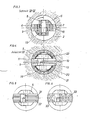
- FIG. 1 and 2 show the implementation of a cased bore, the pivoting jaws being shown in FIG. 1 in the starting position and FIG. 2 in the working position.
- 3 shows a section along line IV-IV of Figure 2
- Figure 4 shows an end view of the jaws in the working position in the direction of arrow III of Figure 2.
- 5 and 6 show an end view of a further embodiment of the drill bit
- FIG. 7 shows an axial section through a further embodiment
- FIG. 8 shows a further axial section through a rotary drill bit according to the invention in the working position.
- 1 represents the tubing with the Schuhkro- J e 20, 2 the borehole wall and 3 the shaft of the drill bit to which the drill pipe or the down-the-hole hammer 19 connects.
- the shoe crown is preferably fitted with cutting tools 22.
- the drill bit 4 has a base body 5, on which two jaws 6 and 7 are articulated by means of a bolt 8. 9 and 10 are the cutting edges, for example made of hard metal, with which the end faces 11 and 12 of the jaws 6 and 7 are fitted.
- the two jaws 6 and 7 are bound together in the pivoted-in starting position by a binding wire 13 which is pulled through holes 14 and 15 of the jaws 6 and 7. In this position, which is shown in FIG. 1, the largest diameter of the jaws is smaller than the inside diameter of the tubing 1, so that the rod assembly with the drill bit 4 can be inserted through the tubing 1.
- the drill bit is designed for percussive and rotating drilling, and the strikes are carried out either by an in-hole hammer or by a hammer acting on the drill pipe.
- the end faces 11 and 12 of the two jaws 6 and 7 are inclined obliquely from the center of the borehole to the edge of the borehole in the direction of advance.
- the centering ring 18 has grooves 21 on the circumference, which allow passage of the cuttings with the flush.
- the body of the bit can be used for multiple sets of jaws or different types of the same.
- two parallel cutting edges 31, 32 are fastened to the base body 5 of the drill bit, and in FIG. 6, warts 33 are used for the cutting body.
- FIG. 7 shows a wear plate 23 arranged between the crown body and the impact surface of the jaws, which prevents damage to the crown body at the point of transmission of the impact on the jaws and can be exchanged together with them.
- One or more mud channels 24 can pass through the body of the crown, thereby improving the removal of the cuttings from the bottom of the borehole.
- Downhole hammers generally have outlet channels for the rinsing air 25 and / or rinsing water 25 '(see FIG. 7) on the underside next to the receiving part for the drill bit.
- flushing bores 24 running through the crown body such that on the one hand they are exactly opposite the outlet opening of the flushing in the hammer and on the other hand open into the front part of the crown body in such a way that an improved flushing effect is achieved than with a pure flow.
- the drill bit according to the invention is designed as a rotary drill bit 28, as shown in FIG. 8, these flushes run ducts 27-27 'from the center 30 of the crown body.
- the jaws are each provided with cutting inserts 26, which have a clearance angle 29 corresponding to the working purpose.
Landscapes
- Engineering & Computer Science (AREA)
- Life Sciences & Earth Sciences (AREA)
- Geology (AREA)
- Mining & Mineral Resources (AREA)
- Physics & Mathematics (AREA)
- Environmental & Geological Engineering (AREA)
- Fluid Mechanics (AREA)
- General Life Sciences & Earth Sciences (AREA)
- Geochemistry & Mineralogy (AREA)
- Mechanical Engineering (AREA)
- Earth Drilling (AREA)
Applications Claiming Priority (2)
| Application Number | Priority Date | Filing Date | Title |
|---|---|---|---|
| AT243578A AT354960B (de) | 1978-04-06 | 1978-04-06 | Bohrkrone fuer die herstellung von bohrungen in erdreich oder gestein |
| AT2435/78 | 1978-04-06 |
Publications (2)
| Publication Number | Publication Date |
|---|---|
| EP0004674A2 true EP0004674A2 (fr) | 1979-10-17 |
| EP0004674A3 EP0004674A3 (fr) | 1979-10-31 |
Family
ID=3534299
Family Applications (1)
| Application Number | Title | Priority Date | Filing Date |
|---|---|---|---|
| EP79101061A Withdrawn EP0004674A3 (fr) | 1978-04-06 | 1979-04-06 | Trépan pour l'exécution de forages dans le sol et la roche |
Country Status (2)
| Country | Link |
|---|---|
| EP (1) | EP0004674A3 (fr) |
| AT (1) | AT354960B (fr) |
Cited By (2)
| Publication number | Priority date | Publication date | Assignee | Title |
|---|---|---|---|---|
| EP0358786A1 (fr) * | 1988-09-13 | 1990-03-21 | Ing. G. Klemm Bohrtechnik GmbH | Dispositif de forage superposé |
| RU2419713C1 (ru) * | 2010-05-18 | 2011-05-27 | Открытое акционерное общество "Кыштымское машиностроительное объединение" | Раздвижной буровой снаряд |
Families Citing this family (1)
| Publication number | Priority date | Publication date | Assignee | Title |
|---|---|---|---|---|
| DE102014104516A1 (de) * | 2014-03-31 | 2015-10-01 | Sysbohr Gmbh - Bohrtechnik Für Den Spezialtiefbau | Bohrkrone, insbesondere zum Überlagerungsbohren, sowie Bohrvorrichtung mit einer Bohrkrone |
Family Cites Families (12)
| Publication number | Priority date | Publication date | Assignee | Title |
|---|---|---|---|---|
| DE3971C (de) * | H. GÖTZE, Schlossermeister, in Neumünster in Holstein | Erdbohrer | ||
| DE39674C (de) * | A. FAUCK und E. HASENÖRL in Wien | Freifallbohrer für Tiefbohrungen | ||
| FR505941A (fr) * | 1918-11-12 | 1920-08-10 | Chas L Stickney | Perfectionnements aux dispositifs de forage |
| US1428774A (en) * | 1921-09-19 | 1922-09-12 | William R Gardner | Fishtail bit |
| US1733452A (en) * | 1926-12-13 | 1929-10-29 | John W Doody | Underreamer |
| GB297285A (en) * | 1928-03-02 | 1928-09-20 | Colon Dev Co | Improvements in well-boring apparatus |
| GB540027A (en) * | 1940-04-26 | 1941-10-02 | Percy Cox | Improvements in and relating to rock boring and like tools |
| US2397652A (en) * | 1944-02-03 | 1946-04-02 | Jr Woyman B Dunlap | Underreamer |
| US2599167A (en) * | 1946-02-23 | 1952-06-03 | Dionisotti Joseph | Scraping out device for mining boreholes |
| DE830033C (de) * | 1950-01-15 | 1952-01-31 | Guenther Fluegge Dr Ing | Bohrmeissel |
| BE795205A (fr) * | 1972-02-10 | 1973-05-29 | Atlas Copco Ab | Procede et appareillage pour le forage rotatif |
| FR2274780A1 (fr) * | 1974-06-12 | 1976-01-09 | Ugine Aciers | Taillants a boutons pour perforation au rocher au moyen d'un marteau fond de trou a soufflage lateral |
-
1978
- 1978-04-06 AT AT243578A patent/AT354960B/de not_active IP Right Cessation
-
1979
- 1979-04-06 EP EP79101061A patent/EP0004674A3/fr not_active Withdrawn
Cited By (2)
| Publication number | Priority date | Publication date | Assignee | Title |
|---|---|---|---|---|
| EP0358786A1 (fr) * | 1988-09-13 | 1990-03-21 | Ing. G. Klemm Bohrtechnik GmbH | Dispositif de forage superposé |
| RU2419713C1 (ru) * | 2010-05-18 | 2011-05-27 | Открытое акционерное общество "Кыштымское машиностроительное объединение" | Раздвижной буровой снаряд |
Also Published As
| Publication number | Publication date |
|---|---|
| AT354960B (de) | 1980-02-11 |
| EP0004674A3 (fr) | 1979-10-31 |
| ATA243578A (de) | 1979-07-15 |
Similar Documents
| Publication | Publication Date | Title |
|---|---|---|
| DE60117372T2 (de) | Vorrichtung und verfahren zur herstellung einer lateralbohrung | |
| DE69815255T2 (de) | Drebohrmeissel zum Fräsen einer Bohrlochverrohrung und zum Bohren einer unterirdischen Formation | |
| DE60127112T2 (de) | Expandierbarer meissel | |
| DE3633749A1 (de) | Druckluft-schlagbohrverfahren und vorrichtung hierfuer | |
| DE3114612A1 (de) | In ein in hartem gestein, insbesondere felsen, vorzutreibendes bohrloch absenkbare bohrvorrichtung und verfahren zur herstellung eines bohrloches | |
| DE3503893C1 (de) | Bohrvorrichtung | |
| DE2107112A1 (de) | Impulsformendes Element fur Schlag werkzeuge | |
| DE2701044A1 (de) | Erdbohrvorrichtung | |
| DE69119402T2 (de) | Im bohrloch zu gebrauchendes bohrwerkzeug zum bohren vor einer verrohrung | |
| DE2839868A1 (de) | Bohrkrone | |
| DE10328609B3 (de) | Nassbohrwerkzeug, Bohranlage und Verfahren zum Niederbringen einer Bohrung im Boden | |
| DE3939538C2 (fr) | ||
| DE19652530C2 (de) | Imlochhammer | |
| AT501696B1 (de) | Verfahren und vorrichtung zum bohren von löchern in boden- oder gesteinsmaterial | |
| DE2758385C3 (de) | Schlag-Bohreinrichtung für Großlochbohrungen | |
| EP0358786A1 (fr) | Dispositif de forage superposé | |
| EP0004674A2 (fr) | Trépan pour l'exécution de forages dans le sol et la roche | |
| DE3109367C2 (de) | Bohrwerkzeug für Tieflochhämmer | |
| DE60117234T2 (de) | Verfahren zum Bohren eines Bohrlochs unter Verwendung einer bizentrischen Bohrkrone | |
| DE3783699T2 (de) | Drehbohrwerkzeug mit einem ausstellbaren raeumer. | |
| DE1188014B (de) | Gesteinsbohrgeraet mit exzentrisch arbeitendem Bohrwerkzeug | |
| DE3024102A1 (de) | Exzenter-bohrvorrichtung | |
| DE3024218C2 (de) | Schlag-Bohreinrichtungen für Großlochbohrungen | |
| DE102004042195A1 (de) | Erdbohrsystem | |
| DE2155540B2 (de) | Vorrichtung zum Überlagerungsbohren |
Legal Events
| Date | Code | Title | Description |
|---|---|---|---|
| PUAI | Public reference made under article 153(3) epc to a published international application that has entered the european phase |
Free format text: ORIGINAL CODE: 0009012 |
|
| PUAL | Search report despatched |
Free format text: ORIGINAL CODE: 0009013 |
|
| AK | Designated contracting states |
Designated state(s): BE CH DE FR GB IT LU NL SE |
|
| AK | Designated contracting states |
Designated state(s): BE CH DE FR GB IT LU NL SE |
|
| 17P | Request for examination filed | ||
| STAA | Information on the status of an ep patent application or granted ep patent |
Free format text: STATUS: THE APPLICATION HAS BEEN WITHDRAWN |
|
| 18W | Application withdrawn |
Withdrawal date: 19810205 |
|
| RIN1 | Information on inventor provided before grant (corrected) |
Inventor name: SULZER,JOSEF |