EP0004729A2 - Dispositif et procédé pour l'enregistrement de phénomènes optiques répétitifs ultra-rapides - Google Patents
Dispositif et procédé pour l'enregistrement de phénomènes optiques répétitifs ultra-rapides Download PDFInfo
- Publication number
- EP0004729A2 EP0004729A2 EP79300451A EP79300451A EP0004729A2 EP 0004729 A2 EP0004729 A2 EP 0004729A2 EP 79300451 A EP79300451 A EP 79300451A EP 79300451 A EP79300451 A EP 79300451A EP 0004729 A2 EP0004729 A2 EP 0004729A2
- Authority
- EP
- European Patent Office
- Prior art keywords
- laser
- tube
- electron
- image
- pulse train
- Prior art date
- Legal status (The legal status is an assumption and is not a legal conclusion. Google has not performed a legal analysis and makes no representation as to the accuracy of the status listed.)
- Granted
Links
- 230000003287 optical effect Effects 0.000 title claims abstract description 22
- 230000003252 repetitive effect Effects 0.000 title claims abstract description 14
- 238000000034 method Methods 0.000 title claims description 10
- 230000001360 synchronised effect Effects 0.000 claims abstract description 11
- 230000001960 triggered effect Effects 0.000 claims 1
- 239000000975 dye Substances 0.000 description 19
- 230000009021 linear effect Effects 0.000 description 10
- 238000005259 measurement Methods 0.000 description 10
- XKRFYHLGVUSROY-UHFFFAOYSA-N argon Substances [Ar] XKRFYHLGVUSROY-UHFFFAOYSA-N 0.000 description 8
- 229910052786 argon Inorganic materials 0.000 description 6
- 238000010586 diagram Methods 0.000 description 5
- 238000000605 extraction Methods 0.000 description 5
- OAICVXFJPJFONN-UHFFFAOYSA-N Phosphorus Chemical compound [P] OAICVXFJPJFONN-UHFFFAOYSA-N 0.000 description 4
- 239000006096 absorbing agent Substances 0.000 description 2
- 230000000694 effects Effects 0.000 description 2
- 238000005086 pumping Methods 0.000 description 2
- 238000009825 accumulation Methods 0.000 description 1
- 238000013459 approach Methods 0.000 description 1
- 238000004891 communication Methods 0.000 description 1
- 230000005492 condensed matter physics Effects 0.000 description 1
- 230000008878 coupling Effects 0.000 description 1
- 238000010168 coupling process Methods 0.000 description 1
- 238000005859 coupling reaction Methods 0.000 description 1
- 238000001514 detection method Methods 0.000 description 1
- 230000005284 excitation Effects 0.000 description 1
- 238000011835 investigation Methods 0.000 description 1
- 239000000463 material Substances 0.000 description 1
- 238000012544 monitoring process Methods 0.000 description 1
- 230000009022 nonlinear effect Effects 0.000 description 1
- 238000012545 processing Methods 0.000 description 1
- 239000010453 quartz Substances 0.000 description 1
- 238000002310 reflectometry Methods 0.000 description 1
- 238000000926 separation method Methods 0.000 description 1
- VYPSYNLAJGMNEJ-UHFFFAOYSA-N silicon dioxide Inorganic materials O=[Si]=O VYPSYNLAJGMNEJ-UHFFFAOYSA-N 0.000 description 1
- 239000000126 substance Substances 0.000 description 1
Images
Classifications
-
- G—PHYSICS
- G04—HOROLOGY
- G04F—TIME-INTERVAL MEASURING
- G04F13/00—Apparatus for measuring unknown time intervals by means not provided for in groups G04F5/00 - G04F10/00
- G04F13/02—Apparatus for measuring unknown time intervals by means not provided for in groups G04F5/00 - G04F10/00 using optical means
- G04F13/026—Measuring duration of ultra-short light pulses, e.g. in the pico-second range; particular detecting devices therefor
-
- G—PHYSICS
- G03—PHOTOGRAPHY; CINEMATOGRAPHY; ANALOGOUS TECHNIQUES USING WAVES OTHER THAN OPTICAL WAVES; ELECTROGRAPHY; HOLOGRAPHY
- G03B—APPARATUS OR ARRANGEMENTS FOR TAKING PHOTOGRAPHS OR FOR PROJECTING OR VIEWING THEM; APPARATUS OR ARRANGEMENTS EMPLOYING ANALOGOUS TECHNIQUES USING WAVES OTHER THAN OPTICAL WAVES; ACCESSORIES THEREFOR
- G03B39/00—High-speed photography
- G03B39/005—High-speed photography using image converters or amplifiers
Definitions
- This invention relates generally to the measurement and study of optical phenomena which occur at very high repetition rates and which have a time durd--ion in the picosecond or sub-picosecond range.
- the invention is particularly concerned with electron-optical image tube systems for use in obtaining a record of pulses generated from a laser, and also with streak cameras operating with a time resolution in the picosecond or sub-picosecond range and capable of providing direct linear measurement of such ultra-short pulses.
- My UK patent specification No. 1443926 describes an electron-optical image tube system which is particularly suited for use with a continuous wave mode-locked laser and which enables a direct linear intensity profile of the average pulse of a pulse train to be obtained.
- the image tube system described in the aforesaid patent specification comprises a photocathode for receiving repetitive pulse-form light images and converting them to pulses of photoelectrons, an extraction electrode immediately adjacent to the emission side of the photocathode to accelerate the photoelectrons away from the photocathode and project them into a path on the output side of the extraction electrode at increased velocity, deflection electrodes on the path of the photoelectrons beyond the extraction electrode, means defining an aperture beyond said deflection electrodes on which the photoelectrons are arranged to impinge, the deflection electrodes being arranged to cause the electrons to follow a path at the aperture-defining means having a rotational component of motion about the longitudinal axis of the tube, control means adjustable so that the photoelectron pulses may be caused to coincide with the aperture, and detector means on the side of the aperture remote from the electrodes to receive photoelectrons passing through the aperture.
- the means defining the aperture may be a plate positioned on the axis of the tube and perpendicular to the axis, with one or more slits therethrough disposed along radii of the tube.
- the known system may include phase control means to control the phase of the woltage wapplied to the deflection electrodes to produce a circular or spiral deflection path on the means defining the aperture.
- Frequency- tunable mode-locked dye lasers are routinely used in conjunction with picosecond streak cameras for selective excitation and direct measurement of the resulting phenomena, luminous or absorptive, occurring in materials of biological, chemical and condensed matter physics interest.
- the method and apparatus of the present invention have applications also to optical communications, data processing, telecommunications, etc. In all these areas one can have phenomena occurring at very high repetition rates, for example up to gigabits.
- apparatus for obtaining a record of repetitive optical phenomena having durations in the picosecond or sub-picosecond range comprising a streak image tube arranged to receive repetitive pulse-form images and convert them to electron images, and a continuous wave mode-locked laser arranged to generate a repetitive series of pulses, characterised by synchronising means arranged to synchronise the deflection of the electron image in the tube with the repetition rate of the pulse train from the continuous wave mode-locked laser.
- a method of obtaining a record of repetitive optical phenomena having durations in the picosecond or sub-picosecond range in which a continuous wave mode-locked laser generates a repetitive series of pulses which are fed to a streaking image tube, characterised in that the streaking image tube is operated in a continuous scanning mode with the streak deflecting voltage driven synchronously at the repetition frequency of the pulse train from the laser.
- the synchronisation of the image tube streak deflecting voltage with the repetition frequency of the laser pulse train means that instead of the streaks being recorded as transients, successive streaks are superimposed precisely on one another.
- This accumulation of time-resolved data means that one can obtain a steady streak image on the streak tube detector, such as a phosphor screen.
- Data can be accumulated at the rate of the order of 10 8 pulses per second. Because of the low photoelectron currents no image intensification is needed in order to overcome photocathode or electron-optical saturation effects.
- the use of the mode-locked laser in synchronism with a streak camera avoids any non-linear effects in the experimental medium under investigation, since the power of the individual pulses can be kept low, for example by using pulses having an average power of only tens of milliwatts.
- a steady streak image can readily be obtained, which means that if an optical multichannel analyser is used to record and store the superimposed streak images the system is equivalent to a picosecond oscilloscope.
- This use of digital recording and storage techniques enables one to achieve a very convenient system for the study of low light level phenomena with picosecond time resolution.
- the method and apparatus of the present invention involve the use of an electron-optical streaking image tube which forms the basis of the streak camera.
- the image tube is preferably of the type described in my UK patent specification No. 1329977, my UK patent specification No. 1443926 or my UK patent specification No. 1516298.
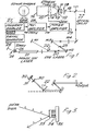
- Fig. 1 shows one arrangement for synchronous operation of a continuous wave mode-locked dye laser and a picosecond streak camera.
- the image tube 10 of the streak camera comprises a photocathode 11, an extraction mesh 12, focussing electrodes 13, an anode 14, a single pair of deflection electrode plates 15, and a phosphor screen 16.
- a pulse train from a variable length optical delay line 17 is filtered in a filter 18 and is passed through a linear slit 19 and is focussed on the photocathode 11.
- the pulse train comes from a continuous wave mode-locked dye laser 20 which is synchronously pumped by an argon ion laser 21.
- the dye laser 20 comprises four mirrors M1, M2, M3 and M4, a quartz prism 22 for frequency narrowing.and tuning, and a dye jet 23. Output coupling is through the mirror M4 which is a 6% transmitting plane mirror.
- the C.W. dye laser 20 is mode-locked by virtue of the fact that the pumping argon ion laser 21 is actively mode-locked with anacousto-opticmodulator indicated generally at 24. This comprises a mode-locking prism 25 fitted with a transducer.
- a signal generator 26 which incorporates a master RF oscillator provides a 70 MHz, 1 watt signal to the transducer of the acousto-optic mode-locking prism 25.
- the signal generator 26 also feeds a 70 MHz, 20mW signal to a frequency doubler 27 which passes a 140 MHz, 20 mW signal to a pre-amplifier 28, which boosts the signal to 1 watt.
- a power amplifier 29 then provides a 140 MHz, 20 W output which is connected by way of a coaxial line to the streak-tube deflection plates 15.
- the driving voltage is preferably sinusoidal and of the order of 3 kV.
- the driving voltage for the deflection plates 15 of the streak tube can provide a linear deflection of more than 5 cm on the phosphor screen 16.
- the synchronously pumped dye laser gives pulses of duration less than 3 picoseconds and the writing speed of the streak camera is adjusted accordingly.
- the optical delay line 17 is arranged to produce two sub- pulses of variable separation from each incident pulse for calibration purposes. A time resolution of the order of 5 picoseconds or less can be achieved with this arrangement.
- Fig. 2 shows an alternative laser arrangement.
- a hybrid system with synchronous pumping and the use of a saturable absorber dye cell.
- the dye laser beam is focussed down by a plano-convex lens 30 into a thin variable-gap dye cell 31 containing a saturable absorber solution flowing in contact with a 100% reflectivity mirror 32.
- This hybrid laser arrangement generates peak power comparable with the laser system of Fig. 1 but at reduced efficiency.
- Fig. 3 shows a pulse train incident on a reflecting mirror 33.
- the mirror is carried on a piezoelectric element 34 which is connected to a suitable voltage supply and is carried on a mechanical mount 35.
- the mechanical scanning system shown in Fig. 3 can be used as an alternative to the use of a relatively slow deflection system inside the image tube lO.
- the optical delay of the laser pulses can be varied by using a scanning mirror driven by for example a piezoelectric mechanical movement.
- the master RF oscillator for the modulator is used also to drive the amplifier 28, 29 to generate the synchronous streak camera deflection voltage signal.
- synchronisation between the laser pulse train and the deflection electrode voltage signal can be achieved by detecting the laser pulses with a photo-detector 36 and then feeding an electrical output signal therefrom to a sync circuit 37 to lock the driving voltage from a signal generator 38 to the pulse train.
- the optical length of the dye laser can be adjusted for optimum performance by adjusting the position of one of the mirrors Ml and M4. These adjustments of the ion laser and of the dye laser can be carried out iteratively until optimum performance of the two lasers is achieved, since the continuously available display of the synchronously driven streak camera provides the necessary monitor of the pulse profiles and intensities.
- an image tube which comprises a photocathode, an extraction electrode in the form of a mesh immediately adjacent to the emission side of the photocathode, a focussing electrode, an anode, opposed pairs of deflector electrodes, and an apertured disc beyond the deflector electrodes and which replaces the conventional phosphor screen.
- an electron multiplier On the output side of the apertured disc there is provided an electron multiplier.
- the aperture in the disc in the aforesaid patent specification is a radially extending slot or slots and the pairs of deflector electrodes are controlled to produce a continuous circular or spiral deflection path on the disc.
- the apertured plate or disc is provided within the image tube itself.
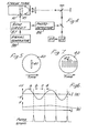
- this image tube plate with a radial slot is replaced by a plate or disc 40 having a slit 41 perpendicular to the axis of the tube as shown in Fig. 5.
- the optical image is thus likewise a slit-form image and an array of photodiodes can be mounted along the length of the slit, inside the tube, or on the end window, to give the desired spatial information about the streak image along the length of the slit.
- Fig. 6 illustrates how the scanning can be carried out in the image tube lO in practice.
- the electron-optical image is deflected repetitively across the plane containing the slit 41 at a rapid speed to give time resolution.
- the deflection voltage is a simple sinusoidal voltage as shown in Fig. 6a applied to the deflection plates 15 and synchronised with the laser pulse train.
- a slowly varying d.c. bias voltage as shown in Fig.-6b is also applied to the deflection electrodes 15 from a separate signal generator, so that the optical image is then scanned across the slit 41 sequentially in order to give the intensity profile in a direction perpendicular to the slit length. This occurs at the same time that the rapidly oscillating sine voltage provides the time resolution.
- the deflection voltage shown in Fig. 6a at a frequency of hundreds of MHz is arranged so that the linear parts ab, cd cover the working area of the plane containing the slit 41.
- the reading scanning voltage shown in'Fig. 6b is arranged to vary slowly compared with the time resolution scanning voltage, for example by arranging that it varies in ramp fashion up and down at a rate of kilohertz or slower.
- a single slit 41 instead of using just a single slit 41, one can use an array of parallel slits 42, each perpendicular to the time-varying direction, as shown in Fig. 7.
- the individual slits 42 are each separated by a distance equal to the slit width, for example of the order of lopm.
- a smaller slow voltage deflection (Fig. 6b) is needed in this case, as compared with the single slit arrangement of Fig. 5, in order to read out the information.
- the necessary spatial deflection is the width of the slit only.
- a charge-coupled detector array can be used and the information read out using electronic techniques only.
- Such a system could be for example an electron-bombarded self-scanned array (ISSA) or an optical multichannel analyser (OMA) at the end of the image tube to record the superimposed streak images.
- ISSA electron-bombarded self-scanned array
- OMA optical multichannel analyser
- the linear intensity profiles can then be displayed subsequently on an oscilloscope or printed out with a penrecorder.
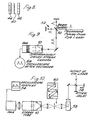
- Fig. 8 shows the use of a microchannel plate amplifier 44 positioned in front of the apertured plate 40 in the image tube with an array of photodetectors 46 behind the plate.
- the microchannel plate amplifier 44 can be mounted in front of the ISSA or similar device to act as a preamplifier.
- Fig. 9 shows an arrangement, using a synchronously driven streak camera, which, by the use of a beam splitter 50 and an interferometer 52, enables each laser pulse to be doubled in order to give a time-scale.
- the image tube lO is here shown as including an optical multichannel analyser (OMA) connected to an oscilloscope or pen recorder 54. Picosecond pulses from a dye laser are incident on the beam splitter 50 and by varying one arm of the interferometer 52 one can achieve accurate calibration of the linearity of the repetitive scanning deflection.
- OMA optical multichannel analyser
- Fig. 10 shows yet another application of the synchronously_driven streak tube, wherein the streak tube is used for the measurement of dye fluorescence lifetimes.
- the output of a dye laser is passed through an optical delay system 56 and is focussed into a cell 58 containing the sample.
- the output is then dealt with as described above using the streak tube lO, an OMA and an oscilloscope 54.
- the streak tube lO, an OMA and an oscilloscope 54 By this means one can obtain measurements of the fluorescence of dyes with what is essentially a picosecond oscilloscope due to the use of the optical multichannel analyser. Variation of decay times as a function of wavelength can be studied by passing the fluorescence from the sample through a scanning monochromator 60 before the streak tube, as shown in Fig. 10.
Landscapes
- Physics & Mathematics (AREA)
- General Physics & Mathematics (AREA)
- Nonlinear Science (AREA)
- Optics & Photonics (AREA)
- Photometry And Measurement Of Optical Pulse Characteristics (AREA)
- Image-Pickup Tubes, Image-Amplification Tubes, And Storage Tubes (AREA)
- Investigating Or Analysing Materials By Optical Means (AREA)
Applications Claiming Priority (2)
| Application Number | Priority Date | Filing Date | Title |
|---|---|---|---|
| GB1154678 | 1978-03-23 | ||
| GB1154678 | 1978-03-23 |
Publications (3)
| Publication Number | Publication Date |
|---|---|
| EP0004729A2 true EP0004729A2 (fr) | 1979-10-17 |
| EP0004729A3 EP0004729A3 (en) | 1979-10-31 |
| EP0004729B1 EP0004729B1 (fr) | 1983-02-23 |
Family
ID=9988230
Family Applications (1)
| Application Number | Title | Priority Date | Filing Date |
|---|---|---|---|
| EP79300451A Expired EP0004729B1 (fr) | 1978-03-23 | 1979-03-21 | Dispositif et procédé pour l'enregistrement de phénomènes optiques répétitifs ultra-rapides |
Country Status (4)
| Country | Link |
|---|---|
| US (1) | US4327285A (fr) |
| EP (1) | EP0004729B1 (fr) |
| JP (1) | JPS5529787A (fr) |
| DE (1) | DE2964884D1 (fr) |
Cited By (1)
| Publication number | Priority date | Publication date | Assignee | Title |
|---|---|---|---|---|
| GB2131165A (en) * | 1982-09-28 | 1984-06-13 | Hamamatsu Photonics Kk | Device for measuring low intensity light |
Families Citing this family (28)
| Publication number | Priority date | Publication date | Assignee | Title |
|---|---|---|---|---|
| US4413178A (en) * | 1981-03-23 | 1983-11-01 | University Of Rochester | Sweep drive circuit for a streak camera |
| US4431914A (en) * | 1981-08-27 | 1984-02-14 | The University Of Rochester | Photoelectron switching in semiconductors in the picosecond time domain |
| JPS5895476A (ja) * | 1981-10-15 | 1983-06-07 | ジヨン・ハドランド(フオトグラフイツク・インスツルメンテイシヨン)リミテツド | 画像変換器 |
| US4630925A (en) * | 1982-11-01 | 1986-12-23 | Hamamatsu Corp. | Compact temporal spectral photometer |
| JPS59104519A (ja) * | 1982-12-07 | 1984-06-16 | Hamamatsu Photonics Kk | 高速繰返しパルス光計測装置 |
| JPS59174742A (ja) * | 1983-03-25 | 1984-10-03 | Agency Of Ind Science & Technol | 微小粒子を区分又は選別する方法及びその装置 |
| US4681436A (en) * | 1984-02-28 | 1987-07-21 | Ching Neng H | Femtosecond laser pulse measuring system |
| US4814599A (en) * | 1984-09-28 | 1989-03-21 | The United States Of America As Represented By The United States Department Of Energy | Microchannel plate streak camera |
| JPS61182534A (ja) * | 1985-02-08 | 1986-08-15 | Hamamatsu Photonics Kk | 超高速光現象の多チャンネル同時計測装置 |
| JPS62124443A (ja) * | 1985-11-26 | 1987-06-05 | Hamamatsu Photonics Kk | 光により物体内部の情報を得る装置 |
| JPS62237344A (ja) * | 1986-04-08 | 1987-10-17 | Hamamatsu Photonics Kk | 時間分解測定システム |
| JPS62277538A (ja) * | 1986-05-27 | 1987-12-02 | Hamamatsu Photonics Kk | 3次元物体計測装置 |
| JPS6326555A (ja) * | 1986-07-18 | 1988-02-04 | Hamamatsu Photonics Kk | 光を用いた物体内部構造の3次元計測装置 |
| JPS6331374A (ja) * | 1986-07-25 | 1988-02-10 | Hamamatsu Photonics Kk | 高速現象観測装置 |
| JPH06100532B2 (ja) * | 1986-08-25 | 1994-12-12 | 浜松ホトニクス株式会社 | 高空間・時間分解計測装置 |
| US4769534A (en) * | 1986-11-17 | 1988-09-06 | Tektronix, Inc. | Optical detector with storage effects reduction |
| JPS649325A (en) * | 1987-06-30 | 1989-01-12 | Hamamatsu Photonics Kk | Light waveform observing instrument |
| US4868380A (en) * | 1988-03-02 | 1989-09-19 | Tektronix, Inc. | Optical waveguide photocathode |
| JPH0617819B2 (ja) * | 1988-05-13 | 1994-03-09 | 浜松ホトニクス株式会社 | 電気光学式ストリークカメラ |
| US5003168A (en) * | 1988-12-22 | 1991-03-26 | Alfano Robert R | Trigger circuit for a streak camera sweep drive circuit |
| GB2226693B (en) * | 1988-12-28 | 1993-09-01 | Hamamatsu Photonics Kk | Optical waveform observing apparatus |
| US5034903A (en) * | 1989-01-30 | 1991-07-23 | Alfano Robert R | Apparatus and method for measuring the time evolution of carriers propogating within submicron and micron electronic devices |
| US5083849A (en) * | 1990-05-18 | 1992-01-28 | Tektronix, Inc. | Light signal sampling system |
| DE4023175A1 (de) * | 1990-07-20 | 1992-01-30 | Max Planck Gesellschaft | Verfahren und vorrichtung zum gewinnen von daten zur bestimmung der dauer und frequenzmodulation von ultrakurzen laserpulsen |
| DE19501441C1 (de) * | 1995-01-19 | 1996-04-04 | Seepex Seeberger Gmbh & Co | Mehrflutige Schlauchpumpe |
| US5949065A (en) * | 1997-12-12 | 1999-09-07 | Fastlite | Sweep generator circuit for a streak camera |
| JP2005294801A (ja) * | 2004-03-11 | 2005-10-20 | Advanced Lcd Technologies Development Center Co Ltd | レーザー結晶化装置及びレーザー結晶化方法 |
| US8138460B1 (en) | 2010-03-08 | 2012-03-20 | Jefferson Science Associates, Llc | Radio frequency phototube |
Family Cites Families (2)
| Publication number | Priority date | Publication date | Assignee | Title |
|---|---|---|---|---|
| GB1329977A (en) * | 1970-06-26 | 1973-09-12 | Bradley D J | Electron optical image tubes and image tube streak cameras |
| GB1443926A (en) * | 1972-07-24 | 1976-07-28 | Bradley D J | Elec-ron-optical image tube systems |
-
1979
- 1979-03-21 DE DE7979300451T patent/DE2964884D1/de not_active Expired
- 1979-03-21 EP EP79300451A patent/EP0004729B1/fr not_active Expired
- 1979-03-23 JP JP3418179A patent/JPS5529787A/ja active Granted
- 1979-03-23 US US06/023,312 patent/US4327285A/en not_active Expired - Lifetime
Non-Patent Citations (4)
| Title |
|---|
| IEEE TRANSACTIONS ON INSTRUMENTATION AND MEASUREMENT, vol. IM-25, nr. 4, December 1976, New York, USA, T. HONDA et al.: "Measurements of picosecond laser pulses from mode-locked ND; YAG laser", pages 397-400. * Page 397; figure 1 * * |
| OPTICS COMMUNICATIONS, vol. 26, nr. 2, August 1978, Amsterdam, NL, M.C. ADAMS et al.: "Linear picosecond electron-optical chronoscopy at a repetition rate of 140 MHz", pages 273-276. * Page 273, right-hand column; page 274; page 275, left-hand column; figures 1, 4 * * |
| OPTO ELECTRONICS, vol. 6, nr. 1 January 1974, London, GB, D.J. BRADLEY; "Generation and measurement of frequency-tunable picosecond pulses from dye lasers", pages 25-42. * Pages 29-31; paragraph 3 * * |
| REVIEW OF SCIENTIFIC INSTRUMENTS, vol. 47, nr. 8, August 1976, New York, USA, A.C. WALKER et al.: "Picosecond resolution real-time, linear detection system for 10-mum radiation", pages 915-920. * Page 919, paragraph VI; figures 1, 4 * * |
Cited By (3)
| Publication number | Priority date | Publication date | Assignee | Title |
|---|---|---|---|---|
| GB2131165A (en) * | 1982-09-28 | 1984-06-13 | Hamamatsu Photonics Kk | Device for measuring low intensity light |
| US4611920A (en) * | 1982-09-28 | 1986-09-16 | Hamamatsu Photonics Kabushiki Kaisha | Device for measuring extremely diminished intensity of light |
| USRE33241E (en) * | 1982-09-28 | 1990-06-26 | Hamamatsu Photonics Kabushiki Kaisha | Device for measuring extremely diminished intensity of light |
Also Published As
| Publication number | Publication date |
|---|---|
| JPH0219889B2 (fr) | 1990-05-07 |
| EP0004729B1 (fr) | 1983-02-23 |
| JPS5529787A (en) | 1980-03-03 |
| EP0004729A3 (en) | 1979-10-31 |
| DE2964884D1 (en) | 1983-03-31 |
| US4327285A (en) | 1982-04-27 |
Similar Documents
| Publication | Publication Date | Title |
|---|---|---|
| US4327285A (en) | Electron-optical image tubes and streak cameras | |
| US4694154A (en) | Instruments for measuring light pulses clocked at high repetition rate and electron tube devices therefor | |
| Adams et al. | Linear picosecond electron-optical chronoscopy at a repetition rate of 140 MHz | |
| US4740685A (en) | Double sweep streak camera device | |
| JPS6224737B2 (fr) | ||
| Fleming et al. | Picosecond fluorescence spectroscopy with a streak camera | |
| US4801796A (en) | Streak camera unit with elliptical deflection | |
| US4718761A (en) | Instrument for concurrently measuring ultra-high-speed light signals on a plurality of channels | |
| French et al. | A versatile computer‐controlled spectrometer for hyper Rayleigh and hyper Raman spectroscopy | |
| JPH02262038A (ja) | 光波形測定装置 | |
| US3973117A (en) | Electron-optical image tubes | |
| US5925877A (en) | Optical beam spatial pattern recording device | |
| US8138460B1 (en) | Radio frequency phototube | |
| JPH0466298B2 (fr) | ||
| EP0344986B1 (fr) | Dispositif pour observer des signaux électriques | |
| Adams et al. | Electron optical picosecond streak camera operating at 140 MHz and 165 MHz repetition rates | |
| JP2680398B2 (ja) | 光波形測定装置 | |
| US4947031A (en) | Sampling streak tube with accelerating electrode plate having an opening | |
| Baggs et al. | Subpicosecond chronoscopy using a Photochron IV streak camera | |
| GB2172991A (en) | Concurrently measuring a plurality of light signals | |
| JPS59104519A (ja) | 高速繰返しパルス光計測装置 | |
| Bradley et al. | A new synchroscan streak-camera read-out system for use with CW mode-locked lasers | |
| US20240274422A1 (en) | Single electron and photon radio frequency timer | |
| US3955117A (en) | Optical pulse demodulator | |
| Sibbett et al. | Internally intensified Photochron II streak tube |
Legal Events
| Date | Code | Title | Description |
|---|---|---|---|
| PUAI | Public reference made under article 153(3) epc to a published international application that has entered the european phase |
Free format text: ORIGINAL CODE: 0009012 |
|
| PUAL | Search report despatched |
Free format text: ORIGINAL CODE: 0009013 |
|
| AK | Designated contracting states |
Designated state(s): CH DE FR GB IT NL SE |
|
| AK | Designated contracting states |
Designated state(s): CH DE FR GB IT NL SE |
|
| 17P | Request for examination filed | ||
| ITF | It: translation for a ep patent filed | ||
| GRAA | (expected) grant |
Free format text: ORIGINAL CODE: 0009210 |
|
| AK | Designated contracting states |
Designated state(s): CH DE FR GB IT NL SE |
|
| PG25 | Lapsed in a contracting state [announced via postgrant information from national office to epo] |
Ref country code: SE Effective date: 19830223 Ref country code: NL Effective date: 19830223 Ref country code: CH Effective date: 19830223 |
|
| REF | Corresponds to: |
Ref document number: 2964884 Country of ref document: DE Date of ref document: 19830331 |
|
| REG | Reference to a national code |
Ref country code: CH Ref legal event code: PL |
|
| ET | Fr: translation filed | ||
| NLV1 | Nl: lapsed or annulled due to failure to fulfill the requirements of art. 29p and 29m of the patents act | ||
| PGFP | Annual fee paid to national office [announced via postgrant information from national office to epo] |
Ref country code: FR Payment date: 19840921 Year of fee payment: 6 |
|
| PG25 | Lapsed in a contracting state [announced via postgrant information from national office to epo] |
Ref country code: FR Free format text: LAPSE BECAUSE OF NON-PAYMENT OF DUE FEES Effective date: 19871130 |
|
| REG | Reference to a national code |
Ref country code: FR Ref legal event code: ST |
|
| PGFP | Annual fee paid to national office [announced via postgrant information from national office to epo] |
Ref country code: DE Payment date: 19901130 Year of fee payment: 12 |
|
| PG25 | Lapsed in a contracting state [announced via postgrant information from national office to epo] |
Ref country code: DE Effective date: 19920101 |
|
| PGFP | Annual fee paid to national office [announced via postgrant information from national office to epo] |
Ref country code: GB Payment date: 19980330 Year of fee payment: 20 |
|
| PG25 | Lapsed in a contracting state [announced via postgrant information from national office to epo] |
Ref country code: GB Free format text: LAPSE BECAUSE OF EXPIRATION OF PROTECTION Effective date: 19990320 |
|
| REG | Reference to a national code |
Ref country code: GB Ref legal event code: PE20 Effective date: 19990320 |
|
| PLBE | No opposition filed within time limit |
Free format text: ORIGINAL CODE: 0009261 |
|
| STAA | Information on the status of an ep patent application or granted ep patent |
Free format text: STATUS: NO OPPOSITION FILED WITHIN TIME LIMIT |