EP0004801A2 - Schalter mit einer elektromagnetischen Einrichtung zur schnellen Öffnung des beweglichen Kontaktes - Google Patents
Schalter mit einer elektromagnetischen Einrichtung zur schnellen Öffnung des beweglichen Kontaktes Download PDFInfo
- Publication number
- EP0004801A2 EP0004801A2 EP79400135A EP79400135A EP0004801A2 EP 0004801 A2 EP0004801 A2 EP 0004801A2 EP 79400135 A EP79400135 A EP 79400135A EP 79400135 A EP79400135 A EP 79400135A EP 0004801 A2 EP0004801 A2 EP 0004801A2
- Authority
- EP
- European Patent Office
- Prior art keywords
- contacts
- arm
- circuit
- contact arm
- circuit breaker
- Prior art date
- Legal status (The legal status is an assumption and is not a legal conclusion. Google has not performed a legal analysis and makes no representation as to the accuracy of the status listed.)
- Granted
Links
Images

Classifications
-
- H—ELECTRICITY
- H01—ELECTRIC ELEMENTS
- H01H—ELECTRIC SWITCHES; RELAYS; SELECTORS; EMERGENCY PROTECTIVE DEVICES
- H01H77/00—Protective overload circuit-breaking switches operated by excess current and requiring separate action for resetting
- H01H77/02—Protective overload circuit-breaking switches operated by excess current and requiring separate action for resetting in which the excess current itself provides the energy for opening the contacts, and having a separate reset mechanism
- H01H77/10—Protective overload circuit-breaking switches operated by excess current and requiring separate action for resetting in which the excess current itself provides the energy for opening the contacts, and having a separate reset mechanism with electrodynamic opening
- H01H77/107—Protective overload circuit-breaking switches operated by excess current and requiring separate action for resetting in which the excess current itself provides the energy for opening the contacts, and having a separate reset mechanism with electrodynamic opening characterised by the blow-off force generating means, e.g. current loops
- H01H77/108—Protective overload circuit-breaking switches operated by excess current and requiring separate action for resetting in which the excess current itself provides the energy for opening the contacts, and having a separate reset mechanism with electrodynamic opening characterised by the blow-off force generating means, e.g. current loops comprising magnetisable elements, e.g. flux concentrator, linear slot motor
Definitions
- a known circuit breaker of the kind mentioned (US Pat. No. 3,815,059) comprises a plurality of U-shaped ferromagnetic sheets, aligned to form an open notch for housing the contact arm extending in a direction perpendicular to the plane of the sheets.
- the electromagnetic forces generated by the fault current cause the arm to quickly drive towards the inside of the notch and the opening of the contacts with an effect of limiting the fault current.
- the circuit breaker is of large size, it is difficult to maintain a controlled electrodynamic resistance of the contacts up to a predetermined value of the current without increasing the contact pressure, which would require an oversized operating mechanism.
- the object of the invention is to remedy this drawback and to produce a circuit breaker with controlled electrodynamic resistance up to an overcurrent threshold, and quickly limiter beyond.
- the current flowing through the contact arm generates a magnetic flux in the magnetic circuit with a value less than the saturation value of the derived magnetic circuit. Almost the entire flow follows this derivative circuit of low reluctance and the electromagnetic device exerts on the contact arm a negligible force of attraction.
- the branch circuit becomes saturated and the flow crosses the air gap E containing the contact arm which is attracted quickly.
- the derivative circuit establishes a frank operating threshold of the limiting electromagnetic device and this threshold, defined by the section of the derivative circuit, is chosen to be substantially equal to the threshold of the electromagnetic trigger, or instantaneous trip trigger. tor, which causes the definitive opening of the contacts following the rapid separation generated by the electromagnetic device.
- the main magnetic circuit comprises a U-shaped stirrup whose wings, separated by the first air gap, extend in planes parallel to the longitudinal direction of the arm.
- the derivative circuit is constituted by a pair of tabs of reduced section compared to that of the wings, which extend the wings and join together leaving a small gap or air gap remaining.
- the circuit breaker is advantageously a multipolar circuit breaker with molded case having a toggle operating mechanism and an automatic thermal and electromagnetic trip device ensuring the opening of the contacts when a fault or short-circuit current appears.
- the fast opening electromagnetic device becomes active when a short-circuit current appears to move the movable contact to an intermediate opening position I, and the operating mechanism controlled by the electromagnetic trip device then takes over to drive the contact arm from the intermediate position I to the final opening position 0.
- a multipolar circuit breaker with molded housing 12 having a bottom 14 and a cover 16 comprises a tripping device 15 and a toggle control mechanism 17 common to the different poles.
- a fixed contact 18 connected to an input pad 20 by a conductor 21 and a movable contact 22, carried by a contact arm 28 connected to an output pad 24 by a braid 26 and a connection strip 27.
- a chamber 34 to cut désionisa- tion plates 36 is associated with contacts 18, 22, and a horn 3 8 connected to the conductor 21, guide the arc drawn between the contacts 18, 22 at their separation to breaking chamber 34.
- the contact arm 28 is rotatably mounted in its middle 50 on an axis 48, carried by a support 30 in the shape of a U.
- the ends of the axis 48 are fitted in blind holes 52 of the wings 54 of the U-shaped support 30 (fig. 4).
- a rotary bar 32 secures the supports 30 of the different poles and the toggle mechanism 17 communicates to the support 30 and bar 32 assembly a rotational movement around the axis of the bar 32 to open or close the contacts 18, 22.
- the toggle switch mechanism 17 is controlled by the trigger device 15 for automatic opening on fault current, or by a lever 40 passing through an opening 42 provided in cover 16.
- a molded case circuit breaker is well known to specialists.
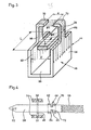
- an electromagnetic member 44 for accelerating the movable contact 22 to the open position comprises, by pole, a U-shaped ferromagnetic stirrup 46 (FIGS. 3 and 4).
- the core 56 of the U-shaped bracket 46 is fixed and centered by lugs 58, 60 at the bottom 14 of the housing 12 and the two wings 62, 64 of the U-shaped bracket 46 extend in the opening direction of the contact 22 in planes parallel to the deflection plane of the contact arm 28, framing a section of length L of the contact arm 28, located between the axis 48 and the braid 26.
- Each wing 62, 64 extends in the direction opening of contact 22 by an extension 66, 68 of length 1 less than L , the ends 70, 72 of which are folded at right angles to face each other and define an air gap e of thickness less than the spacing or air gap E of wings 62, 64.
- the air gap e can be zero.
- the contact arm 28 In the closed position of the contacts 18, 22, the contact arm 28 extends substantially at the ends of the wings 62, 64 of the stirrup 46 and it is easy to see that the current I, flowing at a given time the contact arm 28, generates in the magnetic circuit formed by the stirrup 46, which surrounds the contact arm 28, a magnetic flux which is distributed in two branches (fig. 3).
- the branch crossed by the flow 1 2 comprises the main U-shaped magnetic circuit 56, 62, 64, and the air gap E, and the branch crossed by the flow It comprises the extensions 66, 68 and the air gap e forming a derived circuit magnetic shunt of the main circuit.
- the section of the extensions 66, 68 is notably smaller than that of the main magnetic circuit 56, 62, 64, and this section is chosen to obtain saturation for a value of the current I in the contact arm 28 exceeding a predetermined threshold S M , corresponding to the threshold of the magnetic trigger of the trigger device 15.
- the flow ⁇ 2 borrows the branch to air gap E by exerting on the contact arm 28 an electromagnetic Laplace force which attracts the contact arm 28 towards the bottom of the U-shaped stirrup 46 in position d opening of the contacts 18, 22.
- a compression spring 7 4 is interposed between the core 56 and the contact arm 28 to urge the latter towards the closed position of the contacts 18, 22, the ends 70, 72 serving as a stop limitation of pivoting in this direction.
- the electromagnetic member 44 is active and causes rapid separation of the contacts 18, 22, favoring the increase in the arc voltage and the limitation of the short-circuit current.
- the contact arm 28 is in the intermediate separation position I (FIG. 2, fine lines), and the control mechanism 17, actuated by the electromagnetic trip device after exceeding the threshold S M takes the relay for moving the support 30 and the contact arm 28 towards the stable position 0 of definitive opening (strong lines, FIG. 2), thus preventing any reclosing of the contacts 18, 22.
- the electromagnetic member 44 for accelerating the contact arm 28 maintains an electrodynamic resistance of the contacts 18, 22 up to the overcurrent threshold S M , and the rapid and frank opening of the contacts after the said threshold is exceeded.
- the contact arm 22 is made of a conductive material, preferably non-magnetic. In the case of use of a ferromagnetic material the value of the air gap E is modified.
- the magnetic U-shaped circuit can of course have a different configuration and be arranged differently, for example above the contact arm 28 between the axis 48 and the contact 22.
Landscapes
- Physics & Mathematics (AREA)
- Electromagnetism (AREA)
- Breakers (AREA)
Applications Claiming Priority (2)
| Application Number | Priority Date | Filing Date | Title |
|---|---|---|---|
| FR7809833 | 1978-03-31 | ||
| FR7809833A FR2421458A1 (fr) | 1978-03-31 | 1978-03-31 | Disjoncteur multipolaire a dispositif electromagnetique d'ouverture rapide du contact mobile |
Publications (3)
| Publication Number | Publication Date |
|---|---|
| EP0004801A2 true EP0004801A2 (de) | 1979-10-17 |
| EP0004801A3 EP0004801A3 (en) | 1979-10-31 |
| EP0004801B1 EP0004801B1 (de) | 1982-02-03 |
Family
ID=9206613
Family Applications (1)
| Application Number | Title | Priority Date | Filing Date |
|---|---|---|---|
| EP79400135A Expired EP0004801B1 (de) | 1978-03-31 | 1979-03-05 | Schalter mit einer elektromagnetischen Einrichtung zur schnellen Öffnung des beweglichen Kontaktes |
Country Status (6)
| Country | Link |
|---|---|
| US (1) | US4219790A (de) |
| EP (1) | EP0004801B1 (de) |
| JP (1) | JPS54161074A (de) |
| CA (1) | CA1101025A (de) |
| DE (1) | DE2962017D1 (de) |
| FR (1) | FR2421458A1 (de) |
Cited By (2)
| Publication number | Priority date | Publication date | Assignee | Title |
|---|---|---|---|---|
| EP0177437A3 (en) * | 1984-09-28 | 1987-08-19 | Siemens Aktiengesellschaft Berlin Und Munchen | Contact assembly for a power circuit breaker with current-dependant break |
| FR2612687A1 (fr) * | 1987-03-18 | 1988-09-23 | Licentia Gmbh | Commutateur de puissance electrique comportant un systeme de contacts a ouverture electro-dynamique |
Families Citing this family (4)
| Publication number | Priority date | Publication date | Assignee | Title |
|---|---|---|---|---|
| FR2547122B1 (fr) * | 1983-06-03 | 1985-07-05 | Merlin Gerin | Declencheur electronique selectif associe a un disjoncteur limiteur |
| JPS63308820A (ja) * | 1987-06-10 | 1988-12-16 | Fuji Electric Co Ltd | 回路遮断器の接触子装置 |
| US4835501A (en) * | 1987-09-11 | 1989-05-30 | Cooper Industries, Inc. | Current limiting assembly for circuit breakers |
| FR2788164B1 (fr) * | 1998-12-30 | 2001-02-16 | Schneider Electric Ind Sa | Appareillage electrique de coupure dont un organe de contact est muni d'une fente |
Family Cites Families (7)
| Publication number | Priority date | Publication date | Assignee | Title |
|---|---|---|---|---|
| DE827821C (de) * | 1950-01-21 | 1952-01-14 | Voigt & Haeffner Ag | Unverzoegerter magnetischer UEberstromausloeser |
| US3263042A (en) * | 1963-02-18 | 1966-07-26 | Westinghouse Electric Corp | Electric control device with electromagnetic contact-biasing means |
| FR2185853B1 (de) * | 1972-05-26 | 1977-12-30 | Merlin Gerin | |
| US3815059A (en) * | 1972-12-01 | 1974-06-04 | Westinghouse Electric Corp | Circuit interrupter comprising electromagnetic opening means |
| DE2348613C2 (de) * | 1973-09-27 | 1975-11-06 | Siemens Ag, 1000 Berlin Und 8000 Muenchen | Selbstschalter, insbesondere Schutzschalter |
| US4056798A (en) * | 1975-09-23 | 1977-11-01 | Westinghouse Electric Corporation | Current limiting circuit breaker |
| US4132968A (en) * | 1977-09-06 | 1979-01-02 | Westinghouse Electric Corp. | Current limiting circuit breaker with improved magnetic drive device |
-
1978
- 1978-03-31 FR FR7809833A patent/FR2421458A1/fr active Granted
-
1979
- 1979-03-05 EP EP79400135A patent/EP0004801B1/de not_active Expired
- 1979-03-05 US US06/017,557 patent/US4219790A/en not_active Expired - Lifetime
- 1979-03-05 DE DE7979400135T patent/DE2962017D1/de not_active Expired
- 1979-03-12 CA CA323,208A patent/CA1101025A/en not_active Expired
- 1979-03-27 JP JP3615879A patent/JPS54161074A/ja active Granted
Cited By (2)
| Publication number | Priority date | Publication date | Assignee | Title |
|---|---|---|---|---|
| EP0177437A3 (en) * | 1984-09-28 | 1987-08-19 | Siemens Aktiengesellschaft Berlin Und Munchen | Contact assembly for a power circuit breaker with current-dependant break |
| FR2612687A1 (fr) * | 1987-03-18 | 1988-09-23 | Licentia Gmbh | Commutateur de puissance electrique comportant un systeme de contacts a ouverture electro-dynamique |
Also Published As
| Publication number | Publication date |
|---|---|
| FR2421458B1 (de) | 1980-09-05 |
| EP0004801B1 (de) | 1982-02-03 |
| FR2421458A1 (fr) | 1979-10-26 |
| US4219790A (en) | 1980-08-26 |
| JPS54161074A (en) | 1979-12-20 |
| DE2962017D1 (en) | 1982-03-11 |
| EP0004801A3 (en) | 1979-10-31 |
| JPS6142371B2 (de) | 1986-09-20 |
| CA1101025A (en) | 1981-05-12 |
Similar Documents
| Publication | Publication Date | Title |
|---|---|---|
| CA1239692A (fr) | Dispositif de commutation a composition variable | |
| FR2578355A1 (fr) | Disjoncteur limiteur de courant | |
| EP0059118B1 (de) | Mehrpoliger elektrischer Schalter mit Strombegrenzungsvorrichtung | |
| EP0004801B1 (de) | Schalter mit einer elektromagnetischen Einrichtung zur schnellen Öffnung des beweglichen Kontaktes | |
| EP2330611B1 (de) | Selektiv-Leistungsschalter | |
| EP0537090B1 (de) | Elektrischer Schützschalter mit Einfügung von zusätzlichen Windungen im Magnetauslöser | |
| EP0013642A1 (de) | Strombegrenzender Selbstschalter für Niederspannung | |
| EP0003447B1 (de) | Vorrichtung zur Beschränkung und Unterbrechung des Stroms | |
| EP3699943B1 (de) | Magnetauslöser für stromunterbrechungsgerät | |
| EP0027404A1 (de) | Elektrischer Miniaturschutzschalter mit gegossenem Gehäuse | |
| EP0232637B1 (de) | Elektrischer Kleinschalter mit Mehrfachkontakt | |
| FR2550376A1 (fr) | Disjoncteur a mecanisme a declenchement automatique et rearmement manuel | |
| EP1134767B1 (de) | Magnetisch wirkende Auslösevorrichtung für einen Schutzschalter, und elektrischer Schutzapparat ausgerüstet mit einer solchen Vorrichtung | |
| EP0047696B1 (de) | Kleinstselbstschalter mit Lichtbogenkontakten | |
| EP1282146A1 (de) | Lichtbogenlöschvorrichtung | |
| EP0310469A1 (de) | Schutzschalter mit Blende zum Unterbrechen des Lichtbogens | |
| EP0566462B1 (de) | Selbstschalter | |
| EP0905735B1 (de) | Schutzschalter mit elektromagnetischen Auslöser mit Antrieb für einen beweglichen und gabelförmigen Kontakt | |
| FR2829869A1 (fr) | Appareil electrique interrupteur muni d'un dispositif de commutation de contact | |
| EP0649156B1 (de) | Schutzeinrichtung dargestellt durch die Reihenschaltung eines Schutzschalters mit einem Schaltgerät | |
| EP0479694B1 (de) | Stromverteilungsvorrichtung für die elektrische Energie einer Verteilertafel | |
| FR2620265A1 (fr) | Ensemble magnetique de declenchement pour disjoncteur | |
| FR2602091A1 (fr) | Interrupteur de circuit | |
| EP0097557B1 (de) | Nebenschlussstromkreis für den Auslöser eines Leistungsschalters | |
| FR2480031A1 (fr) | Disjoncteur limiteur de courant comportant un commutateur commande a la maniere d'un relais et independamment de la ligne protegee |
Legal Events
| Date | Code | Title | Description |
|---|---|---|---|
| PUAI | Public reference made under article 153(3) epc to a published international application that has entered the european phase |
Free format text: ORIGINAL CODE: 0009012 |
|
| PUAL | Search report despatched |
Free format text: ORIGINAL CODE: 0009013 |
|
| AK | Designated contracting states |
Designated state(s): BE CH DE GB IT NL SE |
|
| AK | Designated contracting states |
Designated state(s): BE CH DE GB IT NL SE |
|
| 17P | Request for examination filed | ||
| ITF | It: translation for a ep patent filed | ||
| GRAA | (expected) grant |
Free format text: ORIGINAL CODE: 0009210 |
|
| AK | Designated contracting states |
Designated state(s): BE CH DE GB IT NL SE |
|
| REF | Corresponds to: |
Ref document number: 2962017 Country of ref document: DE Date of ref document: 19820311 |
|
| PGFP | Annual fee paid to national office [announced via postgrant information from national office to epo] |
Ref country code: CH Payment date: 19900322 Year of fee payment: 12 |
|
| PGFP | Annual fee paid to national office [announced via postgrant information from national office to epo] |
Ref country code: NL Payment date: 19900331 Year of fee payment: 12 |
|
| PGFP | Annual fee paid to national office [announced via postgrant information from national office to epo] |
Ref country code: GB Payment date: 19910222 Year of fee payment: 13 |
|
| PGFP | Annual fee paid to national office [announced via postgrant information from national office to epo] |
Ref country code: SE Payment date: 19910320 Year of fee payment: 13 |
|
| ITTA | It: last paid annual fee | ||
| PG25 | Lapsed in a contracting state [announced via postgrant information from national office to epo] |
Ref country code: CH Effective date: 19910331 |
|
| PGFP | Annual fee paid to national office [announced via postgrant information from national office to epo] |
Ref country code: BE Payment date: 19910503 Year of fee payment: 13 |
|
| PG25 | Lapsed in a contracting state [announced via postgrant information from national office to epo] |
Ref country code: NL Effective date: 19911001 |
|
| NLV4 | Nl: lapsed or anulled due to non-payment of the annual fee | ||
| REG | Reference to a national code |
Ref country code: CH Ref legal event code: PL |
|
| PG25 | Lapsed in a contracting state [announced via postgrant information from national office to epo] |
Ref country code: GB Effective date: 19920305 |
|
| PG25 | Lapsed in a contracting state [announced via postgrant information from national office to epo] |
Ref country code: SE Effective date: 19920306 |
|
| PG25 | Lapsed in a contracting state [announced via postgrant information from national office to epo] |
Ref country code: BE Effective date: 19920331 |
|
| BERE | Be: lapsed |
Owner name: MERLIN GERIN Effective date: 19920331 |
|
| GBPC | Gb: european patent ceased through non-payment of renewal fee | ||
| PGFP | Annual fee paid to national office [announced via postgrant information from national office to epo] |
Ref country code: DE Payment date: 19940915 Year of fee payment: 16 |
|
| EUG | Se: european patent has lapsed |
Ref document number: 79400135.4 Effective date: 19921005 |
|
| PG25 | Lapsed in a contracting state [announced via postgrant information from national office to epo] |
Ref country code: DE Effective date: 19951201 |
|
| PLBE | No opposition filed within time limit |
Free format text: ORIGINAL CODE: 0009261 |
|
| STAA | Information on the status of an ep patent application or granted ep patent |
Free format text: STATUS: NO OPPOSITION FILED WITHIN TIME LIMIT |