EP0004802A1 - Verfahren und Aggregat zum Montieren einer elastischen Ummantelungshülse - Google Patents
Verfahren und Aggregat zum Montieren einer elastischen Ummantelungshülse Download PDFInfo
- Publication number
- EP0004802A1 EP0004802A1 EP79400159A EP79400159A EP0004802A1 EP 0004802 A1 EP0004802 A1 EP 0004802A1 EP 79400159 A EP79400159 A EP 79400159A EP 79400159 A EP79400159 A EP 79400159A EP 0004802 A1 EP0004802 A1 EP 0004802A1
- Authority
- EP
- European Patent Office
- Prior art keywords
- sleeve
- support tube
- sheathing
- tube
- receiving element
- Prior art date
- Legal status (The legal status is an assumption and is not a legal conclusion. Google has not performed a legal analysis and makes no representation as to the accuracy of the status listed.)
- Granted
Links
- 238000000034 method Methods 0.000 title claims abstract description 28
- 230000000694 effects Effects 0.000 claims description 8
- 239000007788 liquid Substances 0.000 claims description 4
- 238000003860 storage Methods 0.000 claims description 4
- 239000013013 elastic material Substances 0.000 claims description 2
- 239000000463 material Substances 0.000 abstract description 4
- 238000013022 venting Methods 0.000 abstract 2
- 229920001971 elastomer Polymers 0.000 description 7
- 239000000806 elastomer Substances 0.000 description 6
- 238000009434 installation Methods 0.000 description 3
- 239000012212 insulator Substances 0.000 description 3
- RYGMFSIKBFXOCR-UHFFFAOYSA-N Copper Chemical compound [Cu] RYGMFSIKBFXOCR-UHFFFAOYSA-N 0.000 description 2
- 241001415961 Gaviidae Species 0.000 description 2
- XEEYBQQBJWHFJM-UHFFFAOYSA-N Iron Chemical compound [Fe] XEEYBQQBJWHFJM-UHFFFAOYSA-N 0.000 description 2
- XAGFODPZIPBFFR-UHFFFAOYSA-N aluminium Chemical compound [Al] XAGFODPZIPBFFR-UHFFFAOYSA-N 0.000 description 2
- 229910052782 aluminium Inorganic materials 0.000 description 2
- 238000005253 cladding Methods 0.000 description 2
- 230000000295 complement effect Effects 0.000 description 2
- 239000004020 conductor Substances 0.000 description 2
- 229910052802 copper Inorganic materials 0.000 description 2
- 239000010949 copper Substances 0.000 description 2
- 239000002654 heat shrinkable material Substances 0.000 description 2
- 238000011065 in-situ storage Methods 0.000 description 2
- 238000002360 preparation method Methods 0.000 description 2
- 230000001681 protective effect Effects 0.000 description 2
- 239000004065 semiconductor Substances 0.000 description 2
- 239000000243 solution Substances 0.000 description 2
- 229920002943 EPDM rubber Polymers 0.000 description 1
- 229920000181 Ethylene propylene rubber Polymers 0.000 description 1
- 239000004606 Fillers/Extenders Substances 0.000 description 1
- 229920000426 Microplastic Polymers 0.000 description 1
- 229910000831 Steel Inorganic materials 0.000 description 1
- 239000000853 adhesive Substances 0.000 description 1
- 230000001070 adhesive effect Effects 0.000 description 1
- 239000002390 adhesive tape Substances 0.000 description 1
- 239000000956 alloy Substances 0.000 description 1
- 229910045601 alloy Inorganic materials 0.000 description 1
- -1 aluminum-polyethylene Chemical group 0.000 description 1
- 230000000903 blocking effect Effects 0.000 description 1
- 125000000484 butyl group Chemical group [H]C([*])([H])C([H])([H])C([H])([H])C([H])([H])[H] 0.000 description 1
- 239000006229 carbon black Substances 0.000 description 1
- 239000002131 composite material Substances 0.000 description 1
- 230000006835 compression Effects 0.000 description 1
- 238000007906 compression Methods 0.000 description 1
- 239000000470 constituent Substances 0.000 description 1
- 238000005520 cutting process Methods 0.000 description 1
- 238000009795 derivation Methods 0.000 description 1
- 238000010292 electrical insulation Methods 0.000 description 1
- 230000005611 electricity Effects 0.000 description 1
- 239000004744 fabric Substances 0.000 description 1
- 229920001973 fluoroelastomer Polymers 0.000 description 1
- 239000011521 glass Substances 0.000 description 1
- 238000010438 heat treatment Methods 0.000 description 1
- 229920002681 hypalon Polymers 0.000 description 1
- 238000002347 injection Methods 0.000 description 1
- 239000007924 injection Substances 0.000 description 1
- 238000003780 insertion Methods 0.000 description 1
- 230000037431 insertion Effects 0.000 description 1
- 238000009413 insulation Methods 0.000 description 1
- 238000009421 internal insulation Methods 0.000 description 1
- 229910052742 iron Inorganic materials 0.000 description 1
- 230000007774 longterm Effects 0.000 description 1
- 238000012423 maintenance Methods 0.000 description 1
- 230000014759 maintenance of location Effects 0.000 description 1
- 238000004519 manufacturing process Methods 0.000 description 1
- 239000000203 mixture Substances 0.000 description 1
- 238000012986 modification Methods 0.000 description 1
- 230000004048 modification Effects 0.000 description 1
- 230000007935 neutral effect Effects 0.000 description 1
- 229920003023 plastic Polymers 0.000 description 1
- 239000004033 plastic Substances 0.000 description 1
- 229920001084 poly(chloroprene) Polymers 0.000 description 1
- 229920000642 polymer Polymers 0.000 description 1
- 239000011347 resin Substances 0.000 description 1
- 229920005989 resin Polymers 0.000 description 1
- 238000005096 rolling process Methods 0.000 description 1
- 239000005060 rubber Substances 0.000 description 1
- 239000004576 sand Substances 0.000 description 1
- 238000007789 sealing Methods 0.000 description 1
- 238000000926 separation method Methods 0.000 description 1
- 229920002379 silicone rubber Polymers 0.000 description 1
- 239000010935 stainless steel Substances 0.000 description 1
- 229910001220 stainless steel Inorganic materials 0.000 description 1
- 239000010959 steel Substances 0.000 description 1
- 239000000126 substance Substances 0.000 description 1
Images



Classifications
-
- H—ELECTRICITY
- H02—GENERATION; CONVERSION OR DISTRIBUTION OF ELECTRIC POWER
- H02G—INSTALLATION OF ELECTRIC CABLES OR LINES, OR OF COMBINED OPTICAL AND ELECTRIC CABLES OR LINES
- H02G1/00—Methods or apparatus specially adapted for installing, maintaining, repairing or dismantling electric cables or lines
- H02G1/14—Methods or apparatus specially adapted for installing, maintaining, repairing or dismantling electric cables or lines for joining or terminating cables
-
- B—PERFORMING OPERATIONS; TRANSPORTING
- B29—WORKING OF PLASTICS; WORKING OF SUBSTANCES IN A PLASTIC STATE IN GENERAL
- B29C—SHAPING OR JOINING OF PLASTICS; SHAPING OF MATERIAL IN A PLASTIC STATE, NOT OTHERWISE PROVIDED FOR; AFTER-TREATMENT OF THE SHAPED PRODUCTS, e.g. REPAIRING
- B29C63/00—Lining or sheathing, i.e. applying preformed layers or sheathings of plastics; Apparatus therefor
- B29C63/18—Lining or sheathing, i.e. applying preformed layers or sheathings of plastics; Apparatus therefor using tubular layers or sheathings
- B29C63/20—Lining or sheathing, i.e. applying preformed layers or sheathings of plastics; Apparatus therefor using tubular layers or sheathings using pressure difference, e.g. vacuum
Definitions
- the present invention relates to a method and a device for fitting an elastic sheathing sleeve.
- the present invention aims generally to solve the problem of the sheathing, by an elastic sleeve of medium elasticity and relatively long, of the outside of a cylinder or the inside of a hollow cylinder.
- FIG. 1 represents a cable end comprising a stranded core 1, an insulator 2, a semiconductor screen 3 (that is to say in cable language, made of a composite material based on polymer made conductive of electricity by suitable carbon black), a conductive covering 4 such as an aluminum or copper strip, and an insulating sheath 5.
- a cable end is for example intended to be connected to a terminal 6; but it should be noted that the terminal can be replaced by a connection member which allows the junction with another cable or the derivation with other cables.
- the length of the insulating sleeve 11 must be approximately 60 cm.
- the insulating sheathing sleeve 11 is a elastic sleeve, it is not possible to introduce it along the end of the cable simply by sliding it because one then obtains repression effects, and the various constituent layers of the cable can be turned up as well as the product to be nonlinear resistance 10.
- the present invention provides a method of fitting a sheathing sleeve, having longitudinal dimensions greater than its transverse dimensions in an elastic material at least radially, on a substantially cylindrical receiving element consisting of: applying the sheathing sleeve against a support tube having substantially the length of the sleeve to be laid, by varying the elasticity radial of this sleeve, keep the sleeve applied against the support tube; sliding the support tube along the receiving element to the desired cladding position, the cladding sleeve being on the tube between the latter and the element; release the sleeve from the support tube and slide the tool outside the support.
- the sheathing sleeve is applied against the support tube by differential pressure effects and this sleeve is held against the support tube under the effect of atmospheric pressure.
- the present invention also relates, as a new industrial product, to the assembly constituted by the support tube on which the expanded or contracted sleeve is kept ready to be placed around a cable or inside a tube respectively. It also relates by way of application to any receiving element such as a cable or the like provided with a sleeve applied according to the method of the invention.
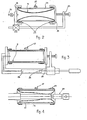
- FIG. 2 illustrates a sheathing sleeve 11, intended to be applied to the external periphery of a receiving member such as the cable 30 illustrated in FIG. 4.
- the sleeve 11 is inserted re inside a hollow support tube 22 of much larger diameter having for example a cylindrical shape.
- the two ends of the sleeve are rolled up towards the outside at each end of the rigid tube 22 and held in place by two washers 23.
- This assembly is then placed between the flanges 24 of a tool 25 of the clamp type.
- These flanges 24 provide a substantially sealed connection with the ends of the tube 22 covered with a portion of the sheathing sleeve 11.
- One of the flanges 24 comprises a valve 26 by which air may be introduced at overpressure, for example at using a compressor or a bicycle pump.
- the tube comprises several closable holes 27.
- the sleeve 11 Under the effect of the overpressure 21, the sleeve 11 is then applied against the internal walls of the rigid tube 22, the air escaping through the openings 27.
- the sleeve 11 then takes the position illustrated in FIG. 3.
- the closable openings 27 are then blocked, for example with the aid of valves or simply with a waterproof adhesive tape.
- the tool 25 is removed and the elastic sleeve 11 remains applied in an expanded or expanded conformation inside the rigid support tube 22, the air no longer being able to return due to the blocking of the orifices 27.
- FIG. 3 represents a variant of the tool 25 of FIG. 2 combining shutter flanges fixed by a clamp and an inflation means of the bicycle pump type 28. This tool will be used for example for in applications if you.
- FIG. 4 illustrates the application of the elastic sleeve 11, previously applied and held by vacuum against the support tube 22, on one end of a cable 30.
- the orifice or orifices 27 are released so as to allow them to enter suddenly or gradually air between the support tube and the elastic sleeve.
- the sleeve then tends to press against the cable 30 first at its central part to take the position shown in dotted lines in Figure 4.
- the upturned ends of the elastic sleeve are released to obtain a finished product such as that shown in Figure 1.
- the release of the ends can be done either by releasing the washers 23 or by cutting the elastomeric sleeve in the vicinity of the end of the support tube 22 or even by releasing the washers 23 followed c ' a cutout of the ends of the sleeve.
- FIG. 5 illustrates another embodiment of the present invention in which the elastic sleeve 11 is provided with skirts or discs 12.
- the support tube 22 can be linked to autonomous flanges 30 instead of a tool of the clamp type as has been illustrated previously, one of the flanges 30 being provided with a device air injection 31, of the bicycle valve type for example.
- the mounting of an elastic sleeve on a support tube according to the present invention is carried out in the factory and the application of the sleeve to the element to be sheathed is carried out in situ.
- the elastic sleeve-support tube assembly it is necessary to store for a certain period the elastic sleeve-support tube assembly, the elastic sleeve having to remain applied against the support tube.
- there are still leaks especially in the case where the aim is to produce a particularly economical device and, in any case, the elastic sleeve is liable to have a certain porosity in air. It is therefore envisaged, according to the present invention, as shown in FIG.
- the elastic sleeve-support tube assembly inside a container 32 containing a neutral liquid 33.
- This container can be a sachet in an aluminum-polyethylene complex.
- the elastic protective sleeve then remains expanded throughout the storage period. In use, the bag is destroyed, the liquid thrown away and the assembly is slipped over the object or end of the cable to be sheathed. Air is then admitted through the openings 27 in the manner described above.
- the rigid support tube 22 can be connected by screwing or snap-fastening to flanges 34 to form an enclosure which is internally stuffed with a powdery product or in grains 35, for example fine or coarse sand, plastic granules ...
- a powdery product or in grains 35 for example fine or coarse sand, plastic granules ...
- the flanges or plugs 34 will be removed, the pulverulent product thrown away and the sleeve placed on the object to be sheathed in the previously explained.
- Figures 8 and 9 illustrate a reverse process of the previous process, in which we want to apply a sleeve to sheath the inside of a receiving tube and not the outside of a cylindrical object.
- This embodiment can in particular be applied to the production of internal seals in pipes, the action of such seals being reinforced by the overpressure possibly existing inside the pipes. Also, it may happen that in some pipes, we want to get provide internal insulation in certain locations, plug cracks or make connections. But, of course, this application is not limited to the case of pipes transferring liquids.
- a support tube 42 of diameter smaller than that of the sheathing sleeve 11 is provided.
- the ends of the sleeve are fixed to the ends of the support tube 42, for example using internal washers 43, but they can of course be fixed to the outside of the support tube. Then, the sleeve 11 is compressed to empty the air pocket between this sleeve and the tube via a closable opening 44.
- This evacuation can be carried out by suction, by compression, by providing for the mounting of the 'support-sleeve tube assembly' in a suitable tool, or simply by manual pressure on the sheath.
- the closable opening 44 is blocked and the sleeve is in the position shown in solid lines in FIG. 9.
- the sleeve assembly tube'support is introduced inside a tube 45 to be sheathed internally; the opening 44 is released to introduce air between the sleeve and the support tube, so that the sleeve is pressed against the internal wall of the receiver tube 45; and the seals or other fastening means 43 are removed.
- access means must be provided to remove the seals 43 and open the openings 44 inside the tube 45. This can be done by example using hooks, or the seals 43 and the valve or other closure means 44 can be connected to extenders escaping towards the outside of the tube.
- One of the fundamental advantages of the present invention is that it does not impose any constraint on the nature of the material constituting the elastic sleeve 11, unlike the case of the use of heat-shrinkable sheaths.
- the composition of these elastic sleeves can therefore be freely chosen according to the problem to be solved.
- the qualities of insulator or conductor of the sheathing sleeve can be freely chosen independently of the effects of temperature.
- the applicant has produced elastomer sleeves with a length of 60 cm and an internal diameter at rest of 20 mm intended to sheath cables 25 mm in diameter, the support tube having an internal diameter of the order of 50 mm, which allows easy positioning of the tube.
- the elastic sheath commonly made of elastomer, does not necessarily have a regular straight cylindrical shape, but may have a shape complementary to the receiving element for which it is intended, for example a connection between two cylinders of different sections.
- the support tube will preferably have a shape complementary to that of the sheathing sleeve.
- FIG. 10 represents a sleeve 60 placed on a support 61 to be placed on an end of a cable with several conductors 62.
- the sleeve 60 has in a way the shape of a glove with pierced fingers and the support 61 has a shape corresponding.
- Figure 11 shows the sleeve placed on a cable.
- Figures 12 and 13 illustrate the installation of a sheath forming a cover 70 on one end of the cylinder 71 using a support tube 72.
- the end of the sheathing sleeve can have the shape illustrated in FIG. 14 to facilitate its initial mounting and the rolling up of its ends on the support tube 22. In this case, after mounting of the elastic sheath on the final receiving element, this will be cut in the vicinity of the location indicated by the dotted line 50.
- the sleeve may take the form of a smooth tube or of a tube provided with discs or skirts forming an insulator produced from elastomer products with a low modulus of elasticity, namely: rubbers, natural and synthetic, silicone elastomers, elastomers based on butyl, polychloroprene, elastomers EPDM or EPR, chlorosulfonated polyethylene, fluoroelastomer, etc.
- this sheathing may be carried out over a product with non-linear resistance such as the product 10 illustrated in FIG. 1, this product preferably being unlikely to drip or to creep due to tightening of the sleeve.
- the non-linear resistance product can also be initially glued inside of the elastic sleeve, this product then follows the expansion of the sleeve at the time of inflation, then is reformed on the cable at the time of deflation.
- the product constituting the elastomeric sleeve itself can contain at a desired level a material giving it a characteristic of non-linear resistance.
- the support tube according to the present invention which allows the expansion and the dilated maintenance of the elastic sheathing sleeve is produced in appropriate dimensions without limitation of diameter or length in a way compatible with easy handling manually or using '' a tool, hoist, etc ...
- This support tube can be made of conventional and known materials such as iron, steel, stainless steel, aluminum, copper and their alloys, plastics, reinforced and laminated elastomers, glass and fabrics impregnated with hot and cold hardening resin, etc.
- the closure for the initial pressurization can be carried out using flanges screwed or fastened quickly to the support tube using quick couplers, bolts and butterfly nuts, or maintained by a tool of the kind clamp.
Landscapes
- Engineering & Computer Science (AREA)
- Manufacturing & Machinery (AREA)
- Cable Accessories (AREA)
- Insulating Bodies (AREA)
- Investigation Of Foundation Soil And Reinforcement Of Foundation Soil By Compacting Or Drainage (AREA)
Applications Claiming Priority (2)
| Application Number | Priority Date | Filing Date | Title |
|---|---|---|---|
| FR7810673A FR2423077A1 (fr) | 1978-04-11 | 1978-04-11 | Nouveau procede et ensemble de pose d'un manchon elastique de gainage |
| FR7810673 | 1978-04-11 |
Publications (2)
| Publication Number | Publication Date |
|---|---|
| EP0004802A1 true EP0004802A1 (de) | 1979-10-17 |
| EP0004802B1 EP0004802B1 (de) | 1983-12-28 |
Family
ID=9206965
Family Applications (1)
| Application Number | Title | Priority Date | Filing Date |
|---|---|---|---|
| EP79400159A Expired EP0004802B1 (de) | 1978-04-11 | 1979-03-09 | Verfahren und Aggregat zum Montieren einer elastischen Ummantelungshülse |
Country Status (5)
| Country | Link |
|---|---|
| EP (1) | EP0004802B1 (de) |
| DE (1) | DE2966503D1 (de) |
| ES (1) | ES479438A1 (de) |
| FR (1) | FR2423077A1 (de) |
| PT (1) | PT69438A (de) |
Cited By (6)
| Publication number | Priority date | Publication date | Assignee | Title |
|---|---|---|---|---|
| FR2503476A1 (fr) * | 1981-04-01 | 1982-10-08 | Fabrication Cables Elect Cie G | Procede de depose d'une gaine protectrice sur l'extremite d'un cable electrique et dispositif pour la mise en oeuvre de celui-ci |
| US4519014A (en) * | 1983-05-09 | 1985-05-21 | Magnetic Controls Company | Cable access assembly |
| FR2592825A1 (fr) * | 1986-01-13 | 1987-07-17 | Artema | Manchon auxiliaire de positionnement, dispositif dote d'un tel manchon et procede de positionnement correspondant |
| AU580268B2 (en) * | 1983-12-27 | 1989-01-12 | Societa' Cavi Pirelli S.P.A. | Process and device for realizing cable joints |
| WO1989011318A1 (fr) * | 1988-05-24 | 1989-11-30 | Braeutigam Hans Juergen | Procede pour produire des tubes a membranes en caoutchouc au silicone avec renforcement mecanique des parois, formation desdits tubes a membranes et leur application |
| EP1006632A1 (de) * | 1998-12-02 | 2000-06-07 | Sagem S.A. | Vorrichtung zum Halten einer elastischen Muffe in ausgedehntem Zustand, sowie Verfahren und Vorrichtung zum Ausdehnen einer elastischen Muffe |
Families Citing this family (2)
| Publication number | Priority date | Publication date | Assignee | Title |
|---|---|---|---|---|
| ZA804854B (en) * | 1979-08-23 | 1981-08-26 | Thomas & Betts Corp | Electrical cable covering assembly |
| FR2674605B1 (fr) * | 1991-03-29 | 1993-06-04 | Silec Liaisons Elec | Manchon elastique conditionne sur un organe support utilisable pour une pose du manchon. |
Citations (8)
| Publication number | Priority date | Publication date | Assignee | Title |
|---|---|---|---|---|
| NL292391A (de) * | 1962-05-04 | 1900-01-01 | ||
| US2560369A (en) * | 1946-03-18 | 1951-07-10 | Roberts Robert Eldon | Method of making flexible tubes |
| US2952298A (en) * | 1959-12-17 | 1960-09-13 | Gustin Bacon Mfg Co | Method and apparatus for affixing flexible tubing to work pieces using tubing from a continuous source |
| FR1321467A (fr) * | 1962-01-09 | 1963-03-22 | Gustin Bacon Mfg Co | Machine pour la pose de gaines élastiques sur des pièces telles que des conduits ou tuyaux |
| US3513051A (en) * | 1966-03-14 | 1970-05-19 | Us Air Force | Method of applying liners with a protective cover,to rocket motor casings |
| FR2086837A5 (de) * | 1970-04-10 | 1971-12-31 | Minnesota Mining & Mfg | |
| FR2183912A1 (de) * | 1972-05-08 | 1973-12-21 | Goodyear Tire & Rubber | |
| FR2234688A1 (de) * | 1973-06-25 | 1975-01-17 | Amp Inc |
-
1978
- 1978-04-11 FR FR7810673A patent/FR2423077A1/fr active Granted
-
1979
- 1979-03-09 EP EP79400159A patent/EP0004802B1/de not_active Expired
- 1979-03-09 DE DE7979400159T patent/DE2966503D1/de not_active Expired
- 1979-04-05 PT PT6943879A patent/PT69438A/pt unknown
- 1979-04-09 ES ES479438A patent/ES479438A1/es not_active Expired
Patent Citations (8)
| Publication number | Priority date | Publication date | Assignee | Title |
|---|---|---|---|---|
| US2560369A (en) * | 1946-03-18 | 1951-07-10 | Roberts Robert Eldon | Method of making flexible tubes |
| US2952298A (en) * | 1959-12-17 | 1960-09-13 | Gustin Bacon Mfg Co | Method and apparatus for affixing flexible tubing to work pieces using tubing from a continuous source |
| FR1321467A (fr) * | 1962-01-09 | 1963-03-22 | Gustin Bacon Mfg Co | Machine pour la pose de gaines élastiques sur des pièces telles que des conduits ou tuyaux |
| NL292391A (de) * | 1962-05-04 | 1900-01-01 | ||
| US3513051A (en) * | 1966-03-14 | 1970-05-19 | Us Air Force | Method of applying liners with a protective cover,to rocket motor casings |
| FR2086837A5 (de) * | 1970-04-10 | 1971-12-31 | Minnesota Mining & Mfg | |
| FR2183912A1 (de) * | 1972-05-08 | 1973-12-21 | Goodyear Tire & Rubber | |
| FR2234688A1 (de) * | 1973-06-25 | 1975-01-17 | Amp Inc |
Cited By (7)
| Publication number | Priority date | Publication date | Assignee | Title |
|---|---|---|---|---|
| FR2503476A1 (fr) * | 1981-04-01 | 1982-10-08 | Fabrication Cables Elect Cie G | Procede de depose d'une gaine protectrice sur l'extremite d'un cable electrique et dispositif pour la mise en oeuvre de celui-ci |
| US4519014A (en) * | 1983-05-09 | 1985-05-21 | Magnetic Controls Company | Cable access assembly |
| AU580268B2 (en) * | 1983-12-27 | 1989-01-12 | Societa' Cavi Pirelli S.P.A. | Process and device for realizing cable joints |
| FR2592825A1 (fr) * | 1986-01-13 | 1987-07-17 | Artema | Manchon auxiliaire de positionnement, dispositif dote d'un tel manchon et procede de positionnement correspondant |
| WO1989011318A1 (fr) * | 1988-05-24 | 1989-11-30 | Braeutigam Hans Juergen | Procede pour produire des tubes a membranes en caoutchouc au silicone avec renforcement mecanique des parois, formation desdits tubes a membranes et leur application |
| EP1006632A1 (de) * | 1998-12-02 | 2000-06-07 | Sagem S.A. | Vorrichtung zum Halten einer elastischen Muffe in ausgedehntem Zustand, sowie Verfahren und Vorrichtung zum Ausdehnen einer elastischen Muffe |
| FR2786954A1 (fr) * | 1998-12-02 | 2000-06-09 | Sagem | Dispositif de maintien en expansion d'un manchon elastique, et procede et dispositif de mise en expansion d'un manchon elastique |
Also Published As
| Publication number | Publication date |
|---|---|
| DE2966503D1 (en) | 1984-02-02 |
| ES479438A1 (es) | 1980-01-01 |
| EP0004802B1 (de) | 1983-12-28 |
| PT69438A (fr) | 1979-05-01 |
| FR2423077B1 (de) | 1981-12-31 |
| FR2423077A1 (fr) | 1979-11-09 |
Similar Documents
| Publication | Publication Date | Title |
|---|---|---|
| EP1033801B1 (de) | Abgedichtete Durchführungsvorrichtung | |
| FR2624665A1 (fr) | Materiau d'etancheite electrique au milieu environnant et procede d'etancheite utilisant ce materiau | |
| EP0504035B1 (de) | Verbindungsvorrichtung für ein oder zwei elektrische Kabel, und Verfahren zum Montieren der Vorrichtung an das Ende des oder der Kabel | |
| FR2581806A1 (fr) | Procede de formation d'epissures de cables, et ensemble ainsi obtenu | |
| EP0004802B1 (de) | Verfahren und Aggregat zum Montieren einer elastischen Ummantelungshülse | |
| FR2964409A1 (fr) | Film polymere pour le conditionnement de tubes d'extraction de petrole | |
| FR2507403A1 (fr) | Procede de realisation de raccords et/ou d'embouts de cables electriques, et raccords et embouts ainsi obtenus | |
| EP1407183B1 (de) | Komprimierte, schalenförmige rohrisolierung | |
| EP0619691B1 (de) | Glasscheibe mit Anschlusselement | |
| WO1998034061A1 (fr) | Enveloppe d'isolation thermique, notamment pour la construction de canalisations sous-marines vehiculant des produits petroliers | |
| EP1166287B1 (de) | Verfahren zur herstellung von überspannungsableiter und überspannungsableiter mit elektrischen varistoren | |
| EP1037352B1 (de) | Träger für schrumpfbare Muffe zum Verbinden von elektrischen Kabeln und Vorrichtung zum Verbinden | |
| EP1413815A1 (de) | Kupplung für zwei Rohre mit aufgeweiteten Enden | |
| WO2008155483A2 (fr) | Conteneur souple de transfert et procédé de fabrication | |
| FR2463972A1 (fr) | Isolateur electrique etanche et flexible pour epissure de cable | |
| FR2831645A1 (fr) | Coquille de calorifugeage compressee | |
| EP1398561A1 (de) | Abstandshalter für Rohre | |
| FR2678765A1 (fr) | Procede de fabrication d'un parafoudre et parafoudre obtenu par mise en óoeuvre de ce procede. | |
| EP0490725B1 (de) | Abdichtungsvorrichtung einer rohrförmigen Kabeldurchführung | |
| FR2594269A1 (fr) | Dispositif pour la protection de jonctions de cables d'energie et d'epissures de cables telephoniques et procede de mise en oeuvre du dispositif. | |
| EP0944934B1 (de) | Verfahren für die erdungskontaktierung einer fernmeldekabelabschirmung und verwendete ausrüstung | |
| EP0506784B1 (de) | Siegel zur feststellung des zugangs zu einem gegenstand | |
| EP0687850A1 (de) | Thermisch isolierte Umhüllung für eine Rohrleitung und Verfahren zu ihrer Herstellung | |
| EP2841342A1 (de) | Steriles einzelset zur herstellung von biopharmazeutischen produkten | |
| FR3048814A1 (fr) | Systeme pour proteger un fil electriquement conducteur |
Legal Events
| Date | Code | Title | Description |
|---|---|---|---|
| PUAI | Public reference made under article 153(3) epc to a published international application that has entered the european phase |
Free format text: ORIGINAL CODE: 0009012 |
|
| AK | Designated contracting states |
Designated state(s): BE CH DE GB IT LU NL |
|
| 17P | Request for examination filed | ||
| 18R | Application refused |
Effective date: 19811212 |
|
| D18R | Application refused (deleted) | ||
| GRAA | (expected) grant |
Free format text: ORIGINAL CODE: 0009210 |
|
| AK | Designated contracting states |
Designated state(s): BE CH DE GB IT LU NL |
|
| D18R | Application refused (deleted) | ||
| PG25 | Lapsed in a contracting state [announced via postgrant information from national office to epo] |
Ref country code: NL Effective date: 19831228 Ref country code: IT Free format text: LAPSE BECAUSE OF FAILURE TO SUBMIT A TRANSLATION OF THE DESCRIPTION OR TO PAY THE FEE WITHIN THE PRESCRIBED TIME-LIMIT;WARNING: LAPSES OF ITALIAN PATENTS WITH EFFECTIVE DATE BEFORE 2007 MAY HAVE OCCURRED AT ANY TIME BEFORE 2007. THE CORRECT EFFECTIVE DATE MAY BE DIFFERENT FROM THE ONE RECORDED. Effective date: 19831228 |
|
| REF | Corresponds to: |
Ref document number: 2966503 Country of ref document: DE Date of ref document: 19840202 |
|
| NLV1 | Nl: lapsed or annulled due to failure to fulfill the requirements of art. 29p and 29m of the patents act | ||
| PLBE | No opposition filed within time limit |
Free format text: ORIGINAL CODE: 0009261 |
|
| STAA | Information on the status of an ep patent application or granted ep patent |
Free format text: STATUS: NO OPPOSITION FILED WITHIN TIME LIMIT |
|
| 26N | No opposition filed | ||
| EPTA | Lu: last paid annual fee | ||
| PGFP | Annual fee paid to national office [announced via postgrant information from national office to epo] |
Ref country code: LU Payment date: 19960201 Year of fee payment: 18 |
|
| PGFP | Annual fee paid to national office [announced via postgrant information from national office to epo] |
Ref country code: GB Payment date: 19960208 Year of fee payment: 18 |
|
| PGFP | Annual fee paid to national office [announced via postgrant information from national office to epo] |
Ref country code: BE Payment date: 19960313 Year of fee payment: 18 |
|
| PGFP | Annual fee paid to national office [announced via postgrant information from national office to epo] |
Ref country code: CH Payment date: 19960319 Year of fee payment: 18 |
|
| PGFP | Annual fee paid to national office [announced via postgrant information from national office to epo] |
Ref country code: DE Payment date: 19960530 Year of fee payment: 18 |
|
| PG25 | Lapsed in a contracting state [announced via postgrant information from national office to epo] |
Ref country code: LU Free format text: LAPSE BECAUSE OF NON-PAYMENT OF DUE FEES Effective date: 19970309 Ref country code: GB Effective date: 19970309 |
|
| PG25 | Lapsed in a contracting state [announced via postgrant information from national office to epo] |
Ref country code: CH Effective date: 19970331 Ref country code: BE Effective date: 19970331 |
|
| BERE | Be: lapsed |
Owner name: SOC. INDUSTRIELLE DE LIAISONS ELECTRIQUES SILEC Effective date: 19970331 |
|
| GBPC | Gb: european patent ceased through non-payment of renewal fee |
Effective date: 19970309 |
|
| REG | Reference to a national code |
Ref country code: CH Ref legal event code: PL |
|
| PG25 | Lapsed in a contracting state [announced via postgrant information from national office to epo] |
Ref country code: DE Effective date: 19971202 |