EP0004805A2 - Sonnenkollektor mit einem die Strahlung selektiv absorbierenden Element - Google Patents
Sonnenkollektor mit einem die Strahlung selektiv absorbierenden Element Download PDFInfo
- Publication number
- EP0004805A2 EP0004805A2 EP79400174A EP79400174A EP0004805A2 EP 0004805 A2 EP0004805 A2 EP 0004805A2 EP 79400174 A EP79400174 A EP 79400174A EP 79400174 A EP79400174 A EP 79400174A EP 0004805 A2 EP0004805 A2 EP 0004805A2
- Authority
- EP
- European Patent Office
- Prior art keywords
- solar energy
- support
- tube
- radiation
- energy collector
- Prior art date
- Legal status (The legal status is an assumption and is not a legal conclusion. Google has not performed a legal analysis and makes no representation as to the accuracy of the status listed.)
- Granted
Links
Images

Classifications
-
- F—MECHANICAL ENGINEERING; LIGHTING; HEATING; WEAPONS; BLASTING
- F24—HEATING; RANGES; VENTILATING
- F24S—SOLAR HEAT COLLECTORS; SOLAR HEAT SYSTEMS
- F24S10/00—Solar heat collectors using working fluids
- F24S10/40—Solar heat collectors using working fluids in absorbing elements surrounded by transparent enclosures, e.g. evacuated solar collectors
- F24S10/45—Solar heat collectors using working fluids in absorbing elements surrounded by transparent enclosures, e.g. evacuated solar collectors the enclosure being cylindrical
-
- F—MECHANICAL ENGINEERING; LIGHTING; HEATING; WEAPONS; BLASTING
- F24—HEATING; RANGES; VENTILATING
- F24S—SOLAR HEAT COLLECTORS; SOLAR HEAT SYSTEMS
- F24S10/00—Solar heat collectors using working fluids
- F24S10/70—Solar heat collectors using working fluids the working fluids being conveyed through tubular absorbing conduits
- F24S10/74—Solar heat collectors using working fluids the working fluids being conveyed through tubular absorbing conduits the tubular conduits are not fixed to heat absorbing plates and are not touching each other
-
- F—MECHANICAL ENGINEERING; LIGHTING; HEATING; WEAPONS; BLASTING
- F24—HEATING; RANGES; VENTILATING
- F24S—SOLAR HEAT COLLECTORS; SOLAR HEAT SYSTEMS
- F24S10/00—Solar heat collectors using working fluids
- F24S10/70—Solar heat collectors using working fluids the working fluids being conveyed through tubular absorbing conduits
- F24S10/75—Solar heat collectors using working fluids the working fluids being conveyed through tubular absorbing conduits with enlarged surfaces, e.g. with protrusions or corrugations
-
- F—MECHANICAL ENGINEERING; LIGHTING; HEATING; WEAPONS; BLASTING
- F24—HEATING; RANGES; VENTILATING
- F24S—SOLAR HEAT COLLECTORS; SOLAR HEAT SYSTEMS
- F24S70/00—Details of absorbing elements
- F24S70/20—Details of absorbing elements characterised by absorbing coatings; characterised by surface treatment for increasing absorption
- F24S70/225—Details of absorbing elements characterised by absorbing coatings; characterised by surface treatment for increasing absorption for spectrally selective absorption
-
- F—MECHANICAL ENGINEERING; LIGHTING; HEATING; WEAPONS; BLASTING
- F24—HEATING; RANGES; VENTILATING
- F24S—SOLAR HEAT COLLECTORS; SOLAR HEAT SYSTEMS
- F24S70/00—Details of absorbing elements
- F24S70/60—Details of absorbing elements characterised by the structure or construction
-
- Y—GENERAL TAGGING OF NEW TECHNOLOGICAL DEVELOPMENTS; GENERAL TAGGING OF CROSS-SECTIONAL TECHNOLOGIES SPANNING OVER SEVERAL SECTIONS OF THE IPC; TECHNICAL SUBJECTS COVERED BY FORMER USPC CROSS-REFERENCE ART COLLECTIONS [XRACs] AND DIGESTS
- Y02—TECHNOLOGIES OR APPLICATIONS FOR MITIGATION OR ADAPTATION AGAINST CLIMATE CHANGE
- Y02E—REDUCTION OF GREENHOUSE GAS [GHG] EMISSIONS, RELATED TO ENERGY GENERATION, TRANSMISSION OR DISTRIBUTION
- Y02E10/00—Energy generation through renewable energy sources
- Y02E10/40—Solar thermal energy, e.g. solar towers
- Y02E10/44—Heat exchange systems
Definitions
- the present invention relates to the field of solar energy collectors.
- It relates to a sensor comprising an element which selectively absorbs radiated energy, that is to say more precisely, which is endowed with a high absorption coefficient in the wavelength range corresponding to light solar, and a low emission coefficient in the wavelength range corresponding to infrared.
- Tubular type solar energy collectors are known, constituted by a cylindrical tube in which a heat transfer fluid circulates.
- the tube is made of glass or metal and it is covered with a layer absorbing solar radiation.
- the sensor further comprises a material reflecting infrared radiation, placed around the absorbent layer.
- the tube can be surrounded by a transparent envelope allowing it to be placed under vacuum, in order to improve its thermal insulation.
- Such a structure therefore leads in particular to the deposition of two layers: a material absorbing the incident radiation and a infrared reflecting material, the first of these at least being deposited on the sensor tube itself, which, in the case where the latter is made of glass, is technologically difficult to achieve, and therefore expensive.
- the subject of the present invention is an element which is both absorbent and selective, in particular intended for solar energy collectors, and making it possible to reduce the manufacturing costs of the latter.
- the support is cylindrical in shape and it is placed around the collector tube with or without contact with the latter, its first surface outwards.
- the element according to the invention can constitute the same wall of the tube.
- FIG. 1a represents, seen in section, an embodiment of the selectively absorbent element according to the invention.
- the support 1 is a rigid sheet of a material having a high thermal conductivity, for example a metal such as silver, gold or copper, or even alumimium, nickel, iron, chromium, etc. ...
- Part 3 receives the incident radiation '30 and is characterized by a high absorptivity coefficient in the field of sunlight and a low emittivity coefficient in the infrared domain. It is obtained from support 1 by treatment of one of the surfaces of the latter: spraying or chemical or electrolytic treatment.
- part 3 can be produced as follows: from a copper support 1, a layer 3 of copper oxide Cu20 is produced by hot etching, which is a quality semiconductor poor, the thickness of which is such that it absorbs solar radiation but is transparent infrared radiation.
- the layer 2 which is highly emissive in the infrared, can be deposited on the surface 12 of the support 1 which is opposite to the part 3, in order to improve the infrared radiation 20 of the element.
- Layer 2 is for example constituted by smoke black, titanium oxide, or even by certain black paints.
- the element according to the invention is particularly applicable to solar energy collectors, as illustrated by way of example in FIGS. 2 and 3.
- a collector may include areas not subjected to solar radiation: It is then advantageous to modify the element of FIG. 1a, in order to reduce the energy losses, as shown in FIG. 1b and described below.
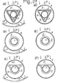
- FIG. 2a represents, seen in section, a solar energy collector.
- the tube 7 can be opened or closed at each of its ends; it contains a heat transfer fluid which circulates therein according to an operation of the open circuit or closed circuit type (heat pipe), this circulation being able to be facilitated by a system operating or not by capillary action, and not described here.
- the entire sensor can be placed at the focal point of a reflector such as an exterior reflector 8, which returns the solar radiation 31 to the tube 7.
- a reflector such as an exterior reflector 8
- the element 5 is then subjected to solar radiation over its entire exterior surface.
- the element 5 is here of cylindrical shape with a triangular base, placed around the tube 7, the layer 2 being on the side of the tube 7.
- the element 5 although seen in section, is not not hatched for clarity.
- the element 5 In the case where the element 5 is placed, in the vacuum envelope 6, without contact with the tube 7, it transmits the energy which it has absorbed only by radiation towards the tube 7.
- the element 5 In the case where, as in Figure 2a, the element 5 is exinscribed to the tube 7, the energy is transmitted to the latter also by conduction at the contact points.
- FIG. 2b makes it possible to further improve the heat transfer between the element 5 and the tube 7.
- FIG. 2c makes it possible to combine the advantages of the two preceding figures at the cost of a slight complication of the shape of the element 5.
- FIG. 2c therefore shows the casing 6, the tube 7, the reflector 8 and the element 5.
- the latter is drawn in such a way that it has a maximum surface area with incident radiation 30: it has a flat surface area 52 , the rest 51 of the surface of the element 5 resulting from a compromise aiming to have a maximum surface in contact with the tube 7 while minimizing the total surface of the part 51.
- This variant also makes it possible to reduce the section of the tube 7, with given incident energy absorption, which makes it possible to reduce the cost of the device.
- Figures 2, d to f show a solar energy sensor similar to the previous ones, but having no reflector.
- Part 5 of the selective absorbent according to the invention which receives the incident radiation 30 is produced in accordance with what is described in FIG.
- the part of the absorbent element which does not receive the radiation 30 re-emits at least the infrared radiation which it receives from the inside in order to limit the energy losses.
- the structure of this part (marked 9) of the element according to the invention is shown in section in Figure lb.
- the support 1 still carries on one of its surfaces 12 the layer 2, but its other surface 11 is now etched and polished to have a high reflection coefficient, therefore of low emittance.
- Figures 3, a to d, show alternative applications of the selectively absorbent element of the invention to a solar energy sensor made of metal.
- a sensor tube 70 has been shown in which a heat transfer fluid circulates, isolated by the vacuum envelope 6, subjected to incident solar radiation 30 and to radiation 31 reflected by the reflector 8.
- the wall of the tube 70 is formed by the selective absorbent described in FIG. 1 a, that is to say comprising a support 1 and a selectively absorbent part 3, but no layer such as 2.
- the solar energy absorbed by the layer 3 is then transmitted to the inner wall of the tube 70 only by conduction, and the layer 2 of the previous figures becomes unnecessary.
- FIG. 3b represents a variant embodiment similar to that of FIG. 2c: the sensor tube 70, constituted as above, further comprises a flat surface 72 of large extent oriented towards the incident radiation 30, and constituted by a metal plate 10, treated on both sides so as to present a selectively absorbent zone 32.
- the solar energy collectors shown in Figures 3c and 3d also include a sensor tube 71 metallic, but without reflector 8.
- the wall of the tube 71 is, like the tube 70 of the preceding figures, constituted by the absorbent element described in FIG. 1 a, without the layer 2, but preferably only on the side of the incident radiation 30.
- the tube 71 is constituted by the single metal support 1, the outer surface 11 of which is etched and polished as described in FIG. 1b, still without the layer 2.
- Figure 3d is a variant corresponding to Figure 3b, but without the reflector 8.
- the entire outer part 11 of the tube 71 is therefore devoid of absorbent layer 3 but polished, and the device further comprises a plate 73 exposed to incident radiation 30 , consisting of a metal sheet 10 whose surface 32 exposed to radiation 30 is made selectively absorbent and the other surface 13 is etched and polished like the surface 11.
Landscapes
- Engineering & Computer Science (AREA)
- Physics & Mathematics (AREA)
- Chemical & Material Sciences (AREA)
- Sustainable Development (AREA)
- Sustainable Energy (AREA)
- Thermal Sciences (AREA)
- Life Sciences & Earth Sciences (AREA)
- Combustion & Propulsion (AREA)
- Mechanical Engineering (AREA)
- General Engineering & Computer Science (AREA)
- Dispersion Chemistry (AREA)
- Spectroscopy & Molecular Physics (AREA)
- Photometry And Measurement Of Optical Pulse Characteristics (AREA)
- Photovoltaic Devices (AREA)
Applications Claiming Priority (2)
| Application Number | Priority Date | Filing Date | Title |
|---|---|---|---|
| FR7809873 | 1978-04-04 | ||
| FR7809873A FR2422117A1 (fr) | 1978-04-04 | 1978-04-04 | Element absorbant selectivement l'energie rayonnee et capteur d'energie solaire comportant un tel element |
Publications (3)
| Publication Number | Publication Date |
|---|---|
| EP0004805A2 true EP0004805A2 (de) | 1979-10-17 |
| EP0004805A3 EP0004805A3 (en) | 1980-02-20 |
| EP0004805B1 EP0004805B1 (de) | 1981-11-25 |
Family
ID=9206639
Family Applications (1)
| Application Number | Title | Priority Date | Filing Date |
|---|---|---|---|
| EP79400174A Expired EP0004805B1 (de) | 1978-04-04 | 1979-03-16 | Sonnenkollektor mit einem die Strahlung selektiv absorbierenden Element |
Country Status (9)
| Country | Link |
|---|---|
| EP (1) | EP0004805B1 (de) |
| AU (1) | AU535326B2 (de) |
| BR (1) | BR7901901A (de) |
| DE (1) | DE2961402D1 (de) |
| ES (1) | ES479181A1 (de) |
| FR (1) | FR2422117A1 (de) |
| IL (1) | IL56994A (de) |
| MX (1) | MX147313A (de) |
| OA (1) | OA06226A (de) |
Cited By (6)
| Publication number | Priority date | Publication date | Assignee | Title |
|---|---|---|---|---|
| DE4335914A1 (de) * | 1992-10-22 | 1994-04-28 | Michael Nord | Solarkollektor |
| US5537991A (en) * | 1994-12-23 | 1996-07-23 | Solar Enterprises International, Llc | Nonimaging solar collector |
| WO2012130283A3 (en) * | 2011-03-29 | 2012-11-22 | Siemens Aktiengesellschaft | Heat receiver tube, method for manufacturing the heat receiver tube, parabolic trough collector with the receiver tube and use of the parabolic trough collector |
| CN103499149A (zh) * | 2013-09-28 | 2014-01-08 | 无锡环特太阳能科技有限公司 | 一种新型分离膜层式太阳能热水器真空管 |
| US20160273804A1 (en) * | 2010-09-23 | 2016-09-22 | Roland Winston | Solar thermal concentrator apparatus, system, and method |
| CN116379621A (zh) * | 2023-04-07 | 2023-07-04 | 天津商业大学 | 一种热泵用内聚焦集热管太阳能蒸发器 |
Families Citing this family (1)
| Publication number | Priority date | Publication date | Assignee | Title |
|---|---|---|---|---|
| WO2010032110A1 (en) * | 2008-09-18 | 2010-03-25 | Kloben S.A.S. Di Turco Adelino E C. | Evacuated tube solar collector device |
Family Cites Families (14)
| Publication number | Priority date | Publication date | Assignee | Title |
|---|---|---|---|---|
| GB821237A (en) * | 1955-03-25 | 1959-10-07 | Hamoetza Hamadait | Improvements in or relating to solar heaters |
| DE2330722A1 (de) * | 1973-06-16 | 1975-01-16 | Nikolaus Laing | Vorrichtung zur rueckfuehrung von kondensat in waermegleichrichterplatten |
| DE2502594C2 (de) * | 1975-01-23 | 1984-05-24 | BOMIN Bochumer Mineralöl GmbH & Co, 4630 Bochum | Sonnenkollektor mit einem aus Metallblechen bestehenden Absorber mit Kanälen für eine die absorbierte Wärme abführende Flüssigkeit |
| US4026272A (en) * | 1975-06-13 | 1977-05-31 | Bottum Edward W | Solar collector |
| US4059093A (en) * | 1975-09-22 | 1977-11-22 | Grumman Aerospace Corporation | Solar energy collector |
| FR2296826A1 (fr) * | 1975-12-24 | 1976-07-30 | Keller Arnold | Collecteur de chaleur solaire et procede pour le former |
| SE396094B (sv) * | 1976-01-05 | 1977-09-05 | Teknoterm Systems Ab | Solenergikollektor |
| DE2604019A1 (de) * | 1976-02-03 | 1977-08-11 | Philips Patentverwaltung | Selektiver absorber fuer strahlung aus dem bereich des sonnenspektrums |
| FR2345675A1 (fr) * | 1976-03-25 | 1977-10-21 | Comp Generale Electricite | Convertisseur d'energie solaire en energie thermique |
| DE2618651C2 (de) * | 1976-04-28 | 1983-04-28 | Philips Patentverwaltung Gmbh, 2000 Hamburg | Sonnenkollektor mit einem langgestreckten Absorber in einem evakuierten Abdeckrohr |
| FR2349802A1 (fr) * | 1976-04-30 | 1977-11-25 | Thomson Csf | Collecteur d'energie solaire |
| DE2622252A1 (de) * | 1976-05-19 | 1977-12-01 | Philips Patentverwaltung | Sonnenkollektor mit einem langgestreckten dewar-gefaess |
| AU504928B2 (en) * | 1976-07-29 | 1979-11-01 | Showa Aluminium K.K. | Solar heat collector |
| CH631540A5 (de) * | 1977-09-24 | 1982-08-13 | Emil Baechli | Sonnenkollektor. |
-
1978
- 1978-04-04 FR FR7809873A patent/FR2422117A1/fr active Granted
-
1979
- 1979-03-16 EP EP79400174A patent/EP0004805B1/de not_active Expired
- 1979-03-16 DE DE7979400174T patent/DE2961402D1/de not_active Expired
- 1979-03-28 BR BR7901901A patent/BR7901901A/pt unknown
- 1979-03-29 MX MX177106A patent/MX147313A/es unknown
- 1979-03-30 AU AU45633/79A patent/AU535326B2/en not_active Ceased
- 1979-04-02 IL IL56994A patent/IL56994A/xx unknown
- 1979-04-02 ES ES479181A patent/ES479181A1/es not_active Expired
- 1979-04-03 OA OA56777A patent/OA06226A/xx unknown
Cited By (13)
| Publication number | Priority date | Publication date | Assignee | Title |
|---|---|---|---|---|
| DE4335914C2 (de) * | 1992-10-22 | 1998-12-03 | Michael Nord | Solarkollektor |
| DE4335914A1 (de) * | 1992-10-22 | 1994-04-28 | Michael Nord | Solarkollektor |
| US5537991A (en) * | 1994-12-23 | 1996-07-23 | Solar Enterprises International, Llc | Nonimaging solar collector |
| US20160273804A1 (en) * | 2010-09-23 | 2016-09-22 | Roland Winston | Solar thermal concentrator apparatus, system, and method |
| US10352589B2 (en) * | 2010-09-23 | 2019-07-16 | Roland Winston | Solar thermal concentrator apparatus, system, and method |
| US20170097175A9 (en) * | 2010-09-23 | 2017-04-06 | Roland Winston | Solar thermal concentrator apparatus, system, and method |
| WO2012130283A3 (en) * | 2011-03-29 | 2012-11-22 | Siemens Aktiengesellschaft | Heat receiver tube, method for manufacturing the heat receiver tube, parabolic trough collector with the receiver tube and use of the parabolic trough collector |
| CN103562654B (zh) * | 2011-03-29 | 2016-08-17 | 西门子聚集太阳能有限公司 | 热接收管、用于制造热接收管的方法、具有接收管的抛物形槽式集热器以及抛物形槽式集热器的用途 |
| CN103562654A (zh) * | 2011-03-29 | 2014-02-05 | 西门子聚集太阳能有限公司 | 热接收管、用于制造热接收管的方法、具有接收管的抛物形槽式集热器以及抛物形槽式集热器的用途 |
| US9732989B2 (en) | 2011-03-29 | 2017-08-15 | Siemens Concentrated Solar Power Ltd. | Heat receiver tube, method for manufacturing the heat receiver tube, parabolic trough collector with the receiver tube and use of the parabolic trough collector |
| CN103499149B (zh) * | 2013-09-28 | 2017-01-25 | 无锡环特太阳能科技有限公司 | 一种分离膜层式太阳能热水器真空管 |
| CN103499149A (zh) * | 2013-09-28 | 2014-01-08 | 无锡环特太阳能科技有限公司 | 一种新型分离膜层式太阳能热水器真空管 |
| CN116379621A (zh) * | 2023-04-07 | 2023-07-04 | 天津商业大学 | 一种热泵用内聚焦集热管太阳能蒸发器 |
Also Published As
| Publication number | Publication date |
|---|---|
| AU4563379A (en) | 1979-10-11 |
| FR2422117A1 (fr) | 1979-11-02 |
| MX147313A (es) | 1982-11-10 |
| FR2422117B1 (de) | 1981-10-30 |
| IL56994A0 (en) | 1979-07-25 |
| IL56994A (en) | 1983-05-15 |
| DE2961402D1 (en) | 1982-01-28 |
| OA06226A (fr) | 1981-06-30 |
| EP0004805B1 (de) | 1981-11-25 |
| EP0004805A3 (en) | 1980-02-20 |
| ES479181A1 (es) | 1979-12-01 |
| AU535326B2 (en) | 1984-03-15 |
| BR7901901A (pt) | 1979-11-27 |
Similar Documents
| Publication | Publication Date | Title |
|---|---|---|
| US4334523A (en) | Solar energy collector having solar selective coating of low reflectance | |
| FR2723633A1 (fr) | Panneau sandwich a nid d'abeilles contenant des tubes de chaleur integres | |
| FR2466864A1 (fr) | Convertisseur thermophotovoltaique | |
| EP0004242A1 (de) | Sonnenlicht Konzentrator | |
| FR2512273A1 (fr) | Lampe a vapeur de metal alcalin haute pression | |
| EP0004805A2 (de) | Sonnenkollektor mit einem die Strahlung selektiv absorbierenden Element | |
| WO2011104479A1 (fr) | Panneau solaire thermique a rendement eleve | |
| JPS5911827B2 (ja) | 集熱部の選択吸収面 | |
| FR2543268A1 (fr) | Appareil de chauffage et/ou de cuisson a energie rayonnante | |
| FR2558569A1 (fr) | Perfectionnements aux appareils d'eclairage pour bicyclettes et autres applications | |
| EP0012678B1 (de) | Solarenergiekollektor | |
| EP0016693A1 (de) | Solarenergie-Kollektorvorrichtung und Verfahren zur Herstellung einer solchen Vorrichtung | |
| CA3142844A1 (fr) | Absorbeur hybride de rayonnements pour centrale solaire, et procede de preparation d'un tel absorbeur | |
| CA1132020A (fr) | Capteur solaire | |
| EP0080961A1 (de) | Wärmeschirm und seine Verwendung in einem Gewächshaus | |
| FR2501846A1 (fr) | Tube pour echangeur thermique et application de ce tube | |
| FR2927154A1 (fr) | Capteur solaire | |
| EP0234962B1 (de) | Rückstrahlungsschirm, seine Herstellungsmethode und seine Verwendung für eine thermische Isolationsvorrichtung | |
| EP0013214B1 (de) | Sonnenenergie absorbierendes Element, mit einem solchen Element versehener Sonnenkollektor und solche Kollektoren enthaltende Sonneplatte | |
| FR2511130A1 (fr) | Capteur solaire a cellules tubulaires | |
| FR2489943A1 (fr) | Dispositif a pouvoir d'emission thermique differentiel pour le transport d'une energie, telle l'energie solaire | |
| WO1995010732A1 (fr) | Generateur de lumiere a bouclier thermique pour ensemble d'eclairage ou d'illumination mettant en oeuvre un guide de lumiere | |
| FR2768522A1 (fr) | Detecteur a scintillation, revetement refracteur pour scintillateur et procede de fabrication d'un tel revetement | |
| FR2567252A1 (fr) | Generateur helio-thermique a faible concentration et rendement eleve | |
| FR2478281A1 (fr) | Procede et installation pour capter un rayonnement et pour l'exploiter dans une enceinte receptrice |
Legal Events
| Date | Code | Title | Description |
|---|---|---|---|
| PUAI | Public reference made under article 153(3) epc to a published international application that has entered the european phase |
Free format text: ORIGINAL CODE: 0009012 |
|
| AK | Designated contracting states |
Designated state(s): DE GB IT NL |
|
| PUAL | Search report despatched |
Free format text: ORIGINAL CODE: 0009013 |
|
| AK | Designated contracting states |
Designated state(s): DE GB IT NL |
|
| 17P | Request for examination filed | ||
| ITF | It: translation for a ep patent filed | ||
| GRAA | (expected) grant |
Free format text: ORIGINAL CODE: 0009210 |
|
| AK | Designated contracting states |
Designated state(s): DE GB IT NL |
|
| REF | Corresponds to: |
Ref document number: 2961402 Country of ref document: DE Date of ref document: 19820128 |
|
| PGFP | Annual fee paid to national office [announced via postgrant information from national office to epo] |
Ref country code: NL Payment date: 19830331 Year of fee payment: 5 |
|
| PG25 | Lapsed in a contracting state [announced via postgrant information from national office to epo] |
Ref country code: NL Effective date: 19841001 |
|
| NLV4 | Nl: lapsed or anulled due to non-payment of the annual fee | ||
| PGFP | Annual fee paid to national office [announced via postgrant information from national office to epo] |
Ref country code: DE Payment date: 19900523 Year of fee payment: 12 |
|
| PGFP | Annual fee paid to national office [announced via postgrant information from national office to epo] |
Ref country code: GB Payment date: 19910301 Year of fee payment: 13 |
|
| ITTA | It: last paid annual fee | ||
| PG25 | Lapsed in a contracting state [announced via postgrant information from national office to epo] |
Ref country code: DE Effective date: 19920101 |
|
| PG25 | Lapsed in a contracting state [announced via postgrant information from national office to epo] |
Ref country code: GB Effective date: 19920316 |
|
| GBPC | Gb: european patent ceased through non-payment of renewal fee | ||
| PLBE | No opposition filed within time limit |
Free format text: ORIGINAL CODE: 0009261 |
|
| STAA | Information on the status of an ep patent application or granted ep patent |
Free format text: STATUS: NO OPPOSITION FILED WITHIN TIME LIMIT |