EP0004842A2 - Relais thermique - Google Patents
Relais thermique Download PDFInfo
- Publication number
- EP0004842A2 EP0004842A2 EP79930002A EP79930002A EP0004842A2 EP 0004842 A2 EP0004842 A2 EP 0004842A2 EP 79930002 A EP79930002 A EP 79930002A EP 79930002 A EP79930002 A EP 79930002A EP 0004842 A2 EP0004842 A2 EP 0004842A2
- Authority
- EP
- European Patent Office
- Prior art keywords
- electrical
- snap disc
- heater
- housing
- contacts
- Prior art date
- Legal status (The legal status is an assumption and is not a legal conclusion. Google has not performed a legal analysis and makes no representation as to the accuracy of the status listed.)
- Granted
Links
Images

Classifications
-
- H—ELECTRICITY
- H01—ELECTRIC ELEMENTS
- H01H—ELECTRIC SWITCHES; RELAYS; SELECTORS; EMERGENCY PROTECTIVE DEVICES
- H01H61/00—Electrothermal relays
- H01H61/02—Electrothermal relays wherein the thermally-sensitive member is heated indirectly, e.g. resistively, inductively
-
- H—ELECTRICITY
- H01—ELECTRIC ELEMENTS
- H01H—ELECTRIC SWITCHES; RELAYS; SELECTORS; EMERGENCY PROTECTIVE DEVICES
- H01H37/00—Thermally-actuated switches
- H01H37/02—Details
- H01H37/10—Compensation for variation of ambient temperature or pressure
Definitions
- time delay relays in which a PTC heater is located in heat transfer relationship with a bimetal snap disc are well known.
- Typical of such devices is the one shown in the U.S. Patent No. 3,858,139 in which a bimetal disc is located in a cup-shaped member to which the PTC heater is adhesively attached.
- one electrical connection to the heater is made by a spring blade biased against the heater and the other connection is made by a second spring blade biased into engagement with the cup-shaped member.
- the bimetal snap disc is arranged such that it moves a yoke having two projections thereon which each actuate a switch when the yoke is moved by the bimetal disc.
- thermal coupling between the PTC heater and the bimetal snap disc is dependent on ambient temperature conditions to a greater extent than is desired because of the terminal extending from outside the housing to make electrical contact to the cup-shaped member.
- thermal coupling between the PTC heater and the bimetal snap disc in the aforementioned prior art device is dependent on the position of the bimetal snap disc to a certain extent.
- the yoke structure used in the prior art device to actuate a pair of switches is subject to substantial variations in size, and these size variations will result in differences in the operating temperature of the two switches.
- the present invention provides a thermal relay construction in which an improved thermal coupling between the PTC heater and bimetal snap disc is obtained by mounting the heater element directly against the bimetal snap disc.
- the thermal coupling of the thermal relay of the present invention is less affected by ambient temperature conditions because the one electrical connection to the heater is made through the bimetal snap disc rather than by a separate terminal extending from outside the housing as in the prior art.
- the thermal relay of the present invention uses two separate actuating pins rather than a yoke with two actuating-extensions as in the prior art to actuate the two switches. By using the two separate actuating pins, the problem with prior art yoke structure is substantially overcome because it is possible to determine the optimum length for each pin separately.
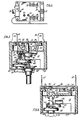
- an electric range oven control embodying the principles of the present invention has a housing assembly which includes a central housing section 12 of plastic or other suitable electrical insulating material having an interior wall 14 which serves to divide the housing into upper and lower cavities 16 and 18, . respectively. Cavities 16 and 18 are closed off by suitable upper and lower insulating plates 20 and 22, respectively, which are attached to housing section 12 by screws 24 or other suitable fasteners. Also mounted on the central housing section is a snap acting micro-switch assembly 26 which is actuated by a capillary action type thermostatic bulb 28. inasmuch as the switch 26 does not form a part of the present invention, it will not be described in detail.
- a plurality of electric terminals denoted by reference numerals 30-44 are riveted to the housing at various positions in order to make electrical contact to electrical components situated within housing cavities 16 and 18.
- Thermostatic bulb 28 is connected to a conventional diaphragm assembly by a tube 48 which extends through a sidewall of central housing section 12.
- Diaphragm assembly 46 is suitably secured to lower housing plate 22 by a hex nut 50 in a conventional manner; and since tube 48 is connected to.diaphragm 46 in a conventional manner, that particular connection is not illustrated in the drawings.
- a substantially conventional adjusting mechanism 52 including a shaft 54 upon which a knob (not shown) carrying suitable temperature indicia is mounted.
- the adjusting mechanism 52 be of the conventional type which controls the oven over the normal operating bake and broil modes.
- Adjustment mechanism 52 as is conventional in the art, accomplishes its adjustment function by providing an adjusting stud 56 which is moved toward a protracted position as the shaft 54 is moved toward higher desired temperature.
- a pair of elongated contact spring blades 60 and 62 having cooperating electrical contacts 64 and 66, respectively, at their interior ends.
- Contacts 64 and 66 form a set of main temperature sensitive electrical contacts which control current flow to the electrical heater of a thermal relay which will hereinafter be described. It will be noted that both spring blades 60 and 62 are biased toward plate 22 and adjustment stud 56 bears against the underside of blade 62 such that the position of contact 66 is determined by adjustment mechanism 52.
- An elongated actuator member 68 is slidably mounted in the interior wall 14 and is axially aligned in abutting contact with diaphragm assembly 46 such that movement of the diaphragm caused by temperature changes in the environment in which bulb 28 is located, causes actuator 68 to move axially also.
- the actuator 68 includes an integral lateral extension 70 which extends to a point beneath a dimpled section 72 of switch blade 60 such that movement of actuator 68 away from plate 22 causes blade 60 to move away from blade 62 to break contacts 64 and 66.
- a pair of normally closed auxiliary contacts are mounted in cavity 16 and include a fixed contact 74 mounted on a bracket extension 76 of terminal 42 and a resilient spring blade 78 riveted to terminal 44.
- the operating point of auxiliary contacts 80 and 82 which are mounted on spring blade 78 and bracket extension 76, respectively, is adjusted by a threaded adjustment screw 84 carried by spring blade 78 aligned axially with actuator 68. Access to adjustment screw 84 is provided through an aperture 86 in the cover plate.
- auxiliary contacts 80 and 82 are designed to operate an auxiliary heater during a self-clean cycle of an electric oven, and accordingly are adjusted to open at approximately 900° F. If the control is to be used in other applications, it will be clear to those skilled in the art that the operating point of the auxiliary contacts can be varied by using actuations of different length.
- thermally sensitive snap disc 88 that is shown in the drawings in its normal unheated position and is effective, when heated to a predetermined temperature, to change from a concave to a convex configuration with a snap action.
- Such snap discs are readily available and are generally contructed of bimetal.
- the peripheral edge of snap disc 88 is held against an integral seating surface of the housing wall 14, such that a change from the normal unheated position shown in the drawings to an opposite position of concavity results in axial movement of the center of disc 88.
- a disc-shaped positive temperature coefficient heater 92 is biased into intimate thermal and electrical contact with snap disc 88 by a spring blade 94 mounted upon housing section 12 at terminal 30. It will be seen that disc-shaped heater 92 is held on spring blade 94 by three tabs 96 struck out from the blade. Depending upon the ambient temperature range in which the control housing is to be located, it might be necessary to compensate for ambient temperature effects on snap disc 88. This can be accomplished by forming spring blade 94 from thermally sensitive material such as bimetal or compound bimetal.
- the electrical connections to heater 92 are made by spring blade 94 on the one side and snap disc 88 on the other side.
- an electrical connection between bimetal snap disc 88 and electrical terminal 38 is made by a leaf spring member 98 which is riveted to the housing along with terminal 38 and biased against the edge of snap disc 88.
- a pair of contact actuating pins 100 and 102 are mounted for slidable movement in wall 14 and are situated on the upper side of snap disc 88 such that movement of the snap disc is translated to a pair of normally closed switch mechanisms 104 and 106, respectively, which are both located in cavity 16.
- Switch mechanism 104 includes a fixed contact 108 mounted on a bracket extension 110 of terminal 40 and a movable contact 112 mounted at the end of a resilient spring blade 114 suitably riveted to terminal 38 and leaf spring contact 98. Spring blade 114 is biased so that contacts 108 and l12 are normally in engagement.
- Switch mechanism 106 is identical to switch mechanism 104 and is accordingly not shown in the drawings.
- an operating lever 116 connected with microswitch 26 is situated to be moved by actuator 68 so that the microswitch 26 is also operated by the actuator 68 in addition to the main contacts and the auxiliary contacts.
- the operating point of microswitch operating lever 116 is adjusted by an adjusting screw 118 threaded through wall 14 and situated against the operating lever.
- the thermal and electrical coupling between snap disc 88 and heater 92 is accomplished by biasing the heater into engagement with the snap disc.
- an electrically and thermally conductive gasket 120 may be situated between the heater 92 and snap disc 88 as shown in FIGURE 6.
- the gasket 120 is constructed of a mixture of a curable, resilient, compressible resin and a plurality of metallic conductive particles. Suitable materials for the gasket 120 are silicone rubbers and silver coated copper particles. The silicone rubber is prepared and cured in accordance with the manufacturer's directions except that, prior to curing, the metallic particles are added in sufficient quantity to make the finally cured gasket electrically and thermally conductive.
- main contacts 64 and 66 will be open and will be closed as adjustment mechanism 54 is rotated to the desired operating temperature. Closure of main contacts 64 and 66 will complete a circuit to heater 92 which may be traced as follows: terminal 32, spring blade 62, main contacts 66 and 64, spring blade 60, spring blade 94, heater 92, snap disc 88, spring leaf contact 98 and terminal 38. Thus, whenever main contacts are closed a circuit will be completed to heater 92 which will heat snap disc 88 and cause it to overcenter.
- switch mechanisms 104 and 106 which control the oven heaters will be closed a short time after the main contacts have closed. It will be clear, therefore, that the combination of the main contacts 64 and 66, heater 92, snap disc 88 and switch mechanisms 100 and 102 forms a thermal time delay relay.
- actuator 68 will continue to be moved away from plate 22 and will eventually open main contacts 64 and 66 to de-energize heater 92 and allow it to cool. While the heater 92 cools, the disc will cool also and will eventually return to its normal unheated position to open switch mechanisms 104 and 106 so as to de-energize the oven heaters.
- auxiliary contacts 80 and 82 which control current flow to an auxiliary heater used in self-clean mode will remain closed, but the auxiliary heater will not be energized because an external control circuit prevents its energization except in the self-clean mode.
- current flow to electrical heater 92 is provided by an external control circuit through terminal 30.
- actuator 68 will open the auxiliary contacts. The cycle will continue until the external self-clean circuit is de-energized.
Landscapes
- Control Of Resistance Heating (AREA)
- Thermally Actuated Switches (AREA)
Applications Claiming Priority (2)
| Application Number | Priority Date | Filing Date | Title |
|---|---|---|---|
| US05/892,437 US4177443A (en) | 1978-03-31 | 1978-03-31 | Thermal relay and electric range control utilizing the same |
| US892437 | 1978-03-31 |
Publications (3)
| Publication Number | Publication Date |
|---|---|
| EP0004842A2 true EP0004842A2 (fr) | 1979-10-17 |
| EP0004842A3 EP0004842A3 (en) | 1979-10-31 |
| EP0004842B1 EP0004842B1 (fr) | 1982-11-17 |
Family
ID=25399936
Family Applications (1)
| Application Number | Title | Priority Date | Filing Date |
|---|---|---|---|
| EP79930002A Expired EP0004842B1 (fr) | 1978-03-31 | 1979-03-29 | Relais thermique |
Country Status (4)
| Country | Link |
|---|---|
| US (1) | US4177443A (fr) |
| EP (1) | EP0004842B1 (fr) |
| CA (1) | CA1119218A (fr) |
| DE (1) | DE2964041D1 (fr) |
Cited By (3)
| Publication number | Priority date | Publication date | Assignee | Title |
|---|---|---|---|---|
| FR2448219A1 (fr) * | 1979-01-31 | 1980-08-29 | Pierburg Gmbh & Co Kg | Dispositif de commande d'une valve ou d'un interrupteur a temporisation thermique |
| WO1994005030A1 (fr) * | 1992-08-11 | 1994-03-03 | Ellenberger & Poensgen Gmbh | Dispositif protecteur pour un consommateur electrique |
| WO2004102038A1 (fr) | 2003-05-16 | 2004-11-25 | Michael Nassim | Transmission de commande rotative |
Families Citing this family (5)
| Publication number | Priority date | Publication date | Assignee | Title |
|---|---|---|---|---|
| US4365225A (en) * | 1980-05-05 | 1982-12-21 | Texas Instruments Incorporated | Time delay relay with spring clips |
| DE8300960U1 (de) * | 1983-01-15 | 1983-06-09 | Fritz Eichenauer GmbH & Co KG, 6744 Kandel | Temperaturwächter |
| GB9309805D0 (en) * | 1993-05-12 | 1993-06-23 | Strix Ltd | Thermally-actuated switches and thermal actuators |
| US5870014A (en) * | 1996-10-11 | 1999-02-09 | Texas Instruments Incorporated | Thermally actuatable auxiliary electrical switch apparatus |
| US7372356B2 (en) * | 2005-11-01 | 2008-05-13 | Homeease Industrial Co., Ltd. | Concealed adjustable temperature switch |
Family Cites Families (8)
| Publication number | Priority date | Publication date | Assignee | Title |
|---|---|---|---|---|
| DE533139C (de) * | 1926-09-11 | 1931-09-17 | Radio Patents Corp Inc | Einrichtung zum Steuern elektrischer Stromkreise durch ein mittels eines Kohlewiderstandes beheiztes waermeempfindliches Organ |
| US2848580A (en) * | 1954-08-10 | 1958-08-19 | Controls Co Of America | Electrical time delay switch |
| DE1538689B2 (de) * | 1966-08-27 | 1971-09-23 | Licentia Gmbh | Thermischer ausloeser |
| US3582853A (en) * | 1969-09-22 | 1971-06-01 | Therm O Disc Inc | Time delay relay |
| US3858139A (en) * | 1973-07-30 | 1974-12-31 | Texas Instruments Inc | Time-delay relay and method of assembling same |
| US3858140A (en) * | 1973-07-30 | 1974-12-31 | Texas Instruments Inc | Time-delay relay and method of assembling same |
| US3898422A (en) * | 1973-12-26 | 1975-08-05 | Texas Instruments Inc | PTC heater assembly bonding |
| IT1061220B (it) * | 1976-03-18 | 1983-02-28 | Texas Instruments Italia Spa | Perfezionamento nei dispositivi bloccaporta per lavatrici e simili ad azionamento mediante bimetallo a riscaldamento voltmetrico |
-
1978
- 1978-03-31 US US05/892,437 patent/US4177443A/en not_active Expired - Lifetime
-
1979
- 1979-03-29 EP EP79930002A patent/EP0004842B1/fr not_active Expired
- 1979-03-29 DE DE7979930002T patent/DE2964041D1/de not_active Expired
- 1979-03-30 CA CA000324727A patent/CA1119218A/fr not_active Expired
Cited By (4)
| Publication number | Priority date | Publication date | Assignee | Title |
|---|---|---|---|---|
| FR2448219A1 (fr) * | 1979-01-31 | 1980-08-29 | Pierburg Gmbh & Co Kg | Dispositif de commande d'une valve ou d'un interrupteur a temporisation thermique |
| WO1994005030A1 (fr) * | 1992-08-11 | 1994-03-03 | Ellenberger & Poensgen Gmbh | Dispositif protecteur pour un consommateur electrique |
| US5604476A (en) * | 1992-08-11 | 1997-02-18 | Ellenberger & Poensgen Gmbh | Protective device for an electrical consumer |
| WO2004102038A1 (fr) | 2003-05-16 | 2004-11-25 | Michael Nassim | Transmission de commande rotative |
Also Published As
| Publication number | Publication date |
|---|---|
| US4177443A (en) | 1979-12-04 |
| EP0004842B1 (fr) | 1982-11-17 |
| CA1119218A (fr) | 1982-03-02 |
| EP0004842A3 (en) | 1979-10-31 |
| DE2964041D1 (en) | 1982-12-23 |
Similar Documents
| Publication | Publication Date | Title |
|---|---|---|
| USRE31596E (en) | Electric power controllers | |
| CA1088601A (fr) | Regulateur de temperature avec compensation en fonction de la chaleur ambiante | |
| US6080967A (en) | Combined user actuation and thermostat switch assembly | |
| US5191310A (en) | Adjustable cycling switch for electric range | |
| US2394121A (en) | Resettable snap action thermal limit switch | |
| EP0004842B1 (fr) | Relais thermique | |
| US6833782B2 (en) | Bimetal snap disc thermostat with heaters | |
| US2897319A (en) | Electric switch | |
| US4703298A (en) | Thermostat with ceramic mounting pins of resistive material | |
| GB2040574A (en) | Temperature regulators | |
| USRE31597E (en) | Electric power controllers | |
| US3239633A (en) | Narrow temperature differential thermostatic control | |
| US4591820A (en) | Thermostatic electric switch and thermal biasing assembly therefor | |
| US3870985A (en) | Thermostatic switch with solid state heater | |
| US2635157A (en) | Thermostatic control switch | |
| US5835001A (en) | Temperature-dependent switch having a movable contact carrying a heating resistor | |
| JPH04241899A (ja) | 電気蒸気アイロン | |
| US3421131A (en) | Thermostat assembly | |
| US3786218A (en) | Adjustable thermostatic device with snap switches | |
| US3418617A (en) | Snap-acting, cycling, thermostatic switch | |
| US2870314A (en) | Control device | |
| US3221123A (en) | Thermoresponsive control for electrically energizable heating unit | |
| US2272459A (en) | Thermostatic control | |
| US3254184A (en) | Sequential thermally responsive switch mechanism | |
| US3047705A (en) | Thermostatic control device |
Legal Events
| Date | Code | Title | Description |
|---|---|---|---|
| PUAI | Public reference made under article 153(3) epc to a published international application that has entered the european phase |
Free format text: ORIGINAL CODE: 0009012 |
|
| PUAL | Search report despatched |
Free format text: ORIGINAL CODE: 0009013 |
|
| AK | Designated contracting states |
Designated state(s): DE FR GB |
|
| AK | Designated contracting states |
Designated state(s): DE FR GB |
|
| 17P | Request for examination filed | ||
| GRAA | (expected) grant |
Free format text: ORIGINAL CODE: 0009210 |
|
| AK | Designated contracting states |
Designated state(s): DE FR GB |
|
| REF | Corresponds to: |
Ref document number: 2964041 Country of ref document: DE Date of ref document: 19821223 |
|
| PGFP | Annual fee paid to national office [announced via postgrant information from national office to epo] |
Ref country code: FR Payment date: 19840215 Year of fee payment: 6 |
|
| PGFP | Annual fee paid to national office [announced via postgrant information from national office to epo] |
Ref country code: DE Payment date: 19840217 Year of fee payment: 6 |
|
| PG25 | Lapsed in a contracting state [announced via postgrant information from national office to epo] |
Ref country code: GB Effective date: 19890329 |
|
| GBPC | Gb: european patent ceased through non-payment of renewal fee | ||
| PG25 | Lapsed in a contracting state [announced via postgrant information from national office to epo] |
Ref country code: FR Free format text: LAPSE BECAUSE OF NON-PAYMENT OF DUE FEES Effective date: 19891130 |
|
| PG25 | Lapsed in a contracting state [announced via postgrant information from national office to epo] |
Ref country code: DE Effective date: 19891201 |
|
| REG | Reference to a national code |
Ref country code: FR Ref legal event code: ST |
|
| PLBE | No opposition filed within time limit |
Free format text: ORIGINAL CODE: 0009261 |
|
| STAA | Information on the status of an ep patent application or granted ep patent |
Free format text: STATUS: NO OPPOSITION FILED WITHIN TIME LIMIT |