EP0004875A2 - Dispositif de réglage en hauteur pour un meuble, en particulier une table - Google Patents
Dispositif de réglage en hauteur pour un meuble, en particulier une table Download PDFInfo
- Publication number
- EP0004875A2 EP0004875A2 EP79100844A EP79100844A EP0004875A2 EP 0004875 A2 EP0004875 A2 EP 0004875A2 EP 79100844 A EP79100844 A EP 79100844A EP 79100844 A EP79100844 A EP 79100844A EP 0004875 A2 EP0004875 A2 EP 0004875A2
- Authority
- EP
- European Patent Office
- Prior art keywords
- furniture
- piece
- spindle drive
- drive
- shaft
- Prior art date
- Legal status (The legal status is an assumption and is not a legal conclusion. Google has not performed a legal analysis and makes no representation as to the accuracy of the status listed.)
- Granted
Links
Images

Classifications
-
- A—HUMAN NECESSITIES
- A47—FURNITURE; DOMESTIC ARTICLES OR APPLIANCES; COFFEE MILLS; SPICE MILLS; SUCTION CLEANERS IN GENERAL
- A47B—TABLES; DESKS; OFFICE FURNITURE; CABINETS; DRAWERS; GENERAL DETAILS OF FURNITURE
- A47B9/00—Tables with tops of variable height
-
- A—HUMAN NECESSITIES
- A47—FURNITURE; DOMESTIC ARTICLES OR APPLIANCES; COFFEE MILLS; SPICE MILLS; SUCTION CLEANERS IN GENERAL
- A47B—TABLES; DESKS; OFFICE FURNITURE; CABINETS; DRAWERS; GENERAL DETAILS OF FURNITURE
- A47B2200/00—General construction of tables or desks
- A47B2200/0035—Tables or desks with features relating to adjustability or folding
- A47B2200/005—Leg adjustment
- A47B2200/0056—Leg adjustment with a motor, e.g. an electric motor
Definitions
- the invention relates to a lifting and lowering device for a piece of furniture, in particular a table, with a drive acting on a part of the piece of furniture which can be raised and lowered relative to a fixed part.
- Lifting and lowering devices of this type enable furniture to be adjusted to different heights. This is of particular importance for work tables, the height of which has to be adapted to the seat height or body size of a working person.
- lifting and lowering devices are known which work according to various possible principles, but have the disadvantage that they have to be complicated and thus expensive to guide the lifting and lowering part of the piece of furniture on the fixed part without tilting.
- tension elements for example wire cables.
- a device of the type mentioned is designed to solve this problem according to the invention in such a way that a spindle drive acting directly in a punctiform manner on the liftable and lowerable part is provided and that the liftable and lowerable part by means of spaced-apart vertical toothed racks on a common, stationary mounted shaft pinions is guided.
- This device is extremely simple and, as will be shown, can be constructed so that it can also be retrofitted to furniture.
- a spindle drive acting directly on the liftable and lowerable part and on the other hand a guide of the liftable and lowerable part on the fixed part is provided, which ensures a non-positive connection of the racks with one another via the stationary shaft, are tilted at the Lifting and lowering movements excluded.
- the spindle drive ensures a very fine working method, and only a small amount of force is required to operate it, so that, for example, a comparatively small electric motor can be used for this purpose.
- the device can advantageously be further developed in such a way that a guide frame is provided, each having a rack-containing telescopic devices, the fixed telescopic parts of which are connected by a horizontal and parallel to the shaft arranged transverse rail.
- This design results in a very rigid guide structure that can be retrofitted as a unit to a piece of furniture, for example on the underside of a table.
- the two telescopic devices can form table legs or can also be attached to side surfaces or table legs.
- the cross rail increases the stability of the piece of furniture significantly, so that the tilt-free guidance of the lifting and lowering part is also improved.
- the spindle drive can be attached to the cross rail in a simple manner in the last-described development, so that it is included in the lifting and lowering unit.
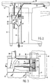
- a work table 10 for example a laboratory table or other equipment table, is shown in a front view, which essentially comprises a table plate 11 which can be raised and lowered, and fixed side parts 12 and 13 which are rigidly connected to one another, for example, by a vertical back plate 14 are.
- the work table 10 contains below the table top 11 a lifting and lowering device which comprises a spindle drive 15, a stationary shaft 16 and two telescopic devices 17 and 18 which are non-positively coupled to this shaft 16.
- the telescopic devices 17 and 18 are connected to the side parts 12 and 13 or fastened to lower cross members 19 and 20 mounted on the side parts 12 and 13.
- the movable elements 21 and 22 of the telescopic devices 17 and 18 are attached to the underside of the table top 11, so that they guide the table top 11 during its lifting and lowering movement in the fixed parts of the telescopic devices 17 and 18. During this movement, tilting of the movable elements 21 and 22 in the telescopic devices 17 and 18 is avoided in that the movable elements 21 and 22 are provided with toothed racks, not shown, which are each guided by a pinion, which is fixed on the shaft 16 . In this way, there is a non-positive coupling of the two movable elements 21 and 22, which in each case ensures corresponding movement lengths during the telescopic movement and thereby makes canting impossible.
- the drive 15 comprises an electric motor 25 which can be reversed with respect to its direction of rotation and which actuates a vertically arranged rotating spindle. This is guided in a sleeve 26 provided in the drive 15 and, by means of its rotary movement, causes a pressure stamp 27 on a thrust rod 28 is more or less far out of the drive 15 or moved into it.
- the pressure stamp 27 can be made of rubber or an elastic plastic, for example, and acts on the table top 11 from below, so that it lifts it or causes it to drop when inserted into the drive 15 due to its own weight.
- the drive 15 is mounted on a cross rail 30 which rigidly connects the two telescopic devices 17 and 18 to one another.
- the drive, the telescopic devices 17 and 18 and the transverse rail 30 thus form a unit which can be mounted on the table 10 in a very simple manner from below.
- the telescopic devices 17 and 18 are only to be connected to the side parts 12 and 13 of the work table 10, and the movable elements 21 and 22 must be fastened to the table top 11. Comparatively weak fastening elements are sufficient for this, since there is no power transmission via the movable elements 21 and 22, but rather they only serve for tilt-free guidance by means of the non-positive coupling realized via the shaft 16.
- the driving force for the lifting movement is transmitted solely to the table top 11 via the pressure stamp 27.
- a connecting cable 40 with a connector 41 for the power supply of the electric motor 25 is also shown.
- an actuating switch 42 can be seen, which is connected to the electric motor 25 via a connecting cable 43 and with two different switching positions enables the electric motor 25 to be actuated in the direction of rotation.
- Fig. 2 shows a sectional view of the lifting and lowering device according to the bleaching direction II indicated in Fig. 1.
- the work table 10 is shown for an uppermost position of the table top 11, the lowest limit position is indicated by dash-dotted lines.
- the view of the Side part 13 shows the telescopic device 17 attached to it and the fastening of the drive 15 by means of two hatch elements 31 and 32, which can be, for example, extended tabs of a mounting bracket 33.
- the tab 31 surrounds the cross rail 30, which has a U-profile and surrounds the shaft 16. It can also be seen that the telescopic device 17 is connected to a lower cross member 19 with the side part 13 of the work table 10.
- the actuation switch 42 for the electric motor 25 of the spindle drive 15 is arranged on the underside of the table top 11 facing a working person near the front edge and is designed as a rocker switch. He T enables a convenient switching on and off of the spindle drive 15 in one or the other possible direction of rotation and thus a very precise adjustment of the height of the table top 11 to the respective requirements.
- the telescopic devices 17 and 18 can be designed in the form of square tubes guided one inside the other. This brings a further improvement in the tilt-free guidance of the table top 11 on the fixed side parts 12 and 13 of the table 10.
- FIG. 3 shows a detail of the lifting and lowering device in accordance with the dash-dotted line in FIG. 1 for better illustration of the guidance of the toothed racks already mentioned, each on a pinion which is fastened on the shaft 16.
- the corresponding part of the lifting and lowering device shown in FIG. 3 is shown partially broken, so that the coupling of a pinion 35 arranged on the shaft 16 to a rack 36 can be seen, which is firmly connected to the movable element 21 of the telescopic device 17 is. It is one on the side part 13 of the Ar beitsticians 10 provided arrangement. This is surrounded by the dash-dotted line G in FIG. 3.
- Fig. 1 shows that a similar unit G is also provided on the side part 12 of the work table 10.
- the pinion 35 is fixed to the shaft 16. This is arranged in a bearing 37, which is shown in FIG. 3 as a simple sleeve and is firmly connected to the cross rail 30.
- the movable element 21 is displaceably guided in the telescopic device 17 in the vertical direction and is provided on its side facing the shaft 16 with a slot, not shown in FIG. 3, which enables movement relative to the shaft 16.
- an arrangement G is provided which is designed analogously to the arrangement of pinion 35 and rack 36 shown in FIG. 3, the two are with the movable elements 21 and 22 the telescopic devices 17 and 18 firmly connected racks non-positively connected to each other via the shaft 16, so that exactly matching lifting and lowering movements of the movable elements 21 and 22 are ensured when the plunger 27 acts on the table top 11 via the push rod 28 or from it Underside is removed.
- the result is a completely trouble-free, low-noise and extremely precise operation of the lifting and lowering device, which is also extremely simple.
- the lifting and lowering device according to the invention thus enables trouble-free guidance of the part moved relative to the fixed part despite the asymmetrical force.
- a device according to the invention can be used wherever the most precise and sensitive way of working is important. For example, use in height-adjustable chairs is also conceivable.
- the device can be used not only with furniture in the narrower sense, but also with all other furnishing or work equipment in which a relatively frequent change in height can be achieved.
Landscapes
- Tables And Desks Characterized By Structural Shape (AREA)
Applications Claiming Priority (2)
| Application Number | Priority Date | Filing Date | Title |
|---|---|---|---|
| DE19782816849 DE2816849A1 (de) | 1978-04-18 | 1978-04-18 | Hebe- und senkvorrichtung fuer ein moebelstueck, insbesondere einen tisch |
| DE2816849 | 1978-04-18 |
Publications (3)
| Publication Number | Publication Date |
|---|---|
| EP0004875A2 true EP0004875A2 (fr) | 1979-10-31 |
| EP0004875A3 EP0004875A3 (en) | 1979-11-14 |
| EP0004875B1 EP0004875B1 (fr) | 1981-05-13 |
Family
ID=6037328
Family Applications (1)
| Application Number | Title | Priority Date | Filing Date |
|---|---|---|---|
| EP79100844A Expired EP0004875B1 (fr) | 1978-04-18 | 1979-03-20 | Dispositif de réglage en hauteur pour un meuble, en particulier une table |
Country Status (2)
| Country | Link |
|---|---|
| EP (1) | EP0004875B1 (fr) |
| DE (2) | DE2816849A1 (fr) |
Cited By (1)
| Publication number | Priority date | Publication date | Assignee | Title |
|---|---|---|---|---|
| CN105725572A (zh) * | 2016-03-03 | 2016-07-06 | 祁旭东 | 一种支架 |
Families Citing this family (2)
| Publication number | Priority date | Publication date | Assignee | Title |
|---|---|---|---|---|
| EP0074019A3 (fr) * | 1981-09-04 | 1985-11-06 | Asea Ab | Pupitre de contrôle |
| US10034538B1 (en) * | 2017-05-05 | 2018-07-31 | Sauder Woodworking Co. | Height-adjustable work surface assembly |
Family Cites Families (3)
| Publication number | Priority date | Publication date | Assignee | Title |
|---|---|---|---|---|
| DE508600C (de) * | 1929-04-19 | 1930-09-29 | Arno Doerr | Als Fachgestell verwendbarer Tisch |
| DE930542C (de) * | 1949-06-26 | 1955-07-18 | Friedrich Moerschner | Gebrauchsmoebel, insbesondere Tische und Stuehle bzw. Polstersessel |
| SE360634B (fr) * | 1972-02-24 | 1973-10-01 | Linden Alimak Ab |
-
1978
- 1978-04-18 DE DE19782816849 patent/DE2816849A1/de not_active Ceased
-
1979
- 1979-03-20 DE DE7979100844T patent/DE2960337D1/de not_active Expired
- 1979-03-20 EP EP79100844A patent/EP0004875B1/fr not_active Expired
Cited By (1)
| Publication number | Priority date | Publication date | Assignee | Title |
|---|---|---|---|---|
| CN105725572A (zh) * | 2016-03-03 | 2016-07-06 | 祁旭东 | 一种支架 |
Also Published As
| Publication number | Publication date |
|---|---|
| DE2816849A1 (de) | 1979-10-25 |
| DE2960337D1 (en) | 1981-08-20 |
| EP0004875B1 (fr) | 1981-05-13 |
| EP0004875A3 (en) | 1979-11-14 |
Similar Documents
| Publication | Publication Date | Title |
|---|---|---|
| EP0017765B1 (fr) | Dispositif de levage hydraulique | |
| DE3521047C1 (de) | Mikroskop | |
| DE29500574U1 (de) | Hebe- und Senkvorrichtung für Möbelelemente | |
| EP0234008A2 (fr) | Balance de précision | |
| EP0074019A2 (fr) | Pupitre de contrôle | |
| DE9116652U1 (de) | Dachdeckelanordnung für ein Kraftfahrzeug | |
| EP0437283A1 (fr) | Toit ouvrant pour véhicules automobiles | |
| EP0401465A2 (fr) | Unité de travail pour la cuisine | |
| DE3127019A1 (de) | "vorrichtung fuer einen submast-hublader mit in fahrzeugrichtung laengsbeweglich gehaltenem batteriewagen" | |
| EP0004875B1 (fr) | Dispositif de réglage en hauteur pour un meuble, en particulier une table | |
| DE2846223A1 (de) | Arbeitstisch | |
| AT501777B1 (de) | Schubladenführung | |
| DE1559725B1 (de) | Hebebeschlag fuer den Fluegelrahmen eines Schiebefensters oder einer Schiebetuer | |
| DE3242523C2 (de) | Einrichtung zur Schnellverstellung von Mikroskoptischen | |
| DE1555632A1 (de) | Scheibenfuehrung fuer in den Fensterschacht eines Fahrzeuges versenkbare Schiebefenster | |
| DE19517656C2 (de) | Hebe- und Senkvorrichtung für Möbelelemente | |
| DE3037375A1 (de) | Hoehenverstellbarer objekttraeger | |
| DE202005000589U1 (de) | Hebeschiebeanlage | |
| DE3207177A1 (de) | Tisch mit einer verstellbaren tischplatte | |
| DE2649868A1 (de) | Zeichentisch fuer hoehenverstellbare zeichenbretter | |
| EP0132448B1 (fr) | Table à plateau réglable | |
| DE2952716A1 (de) | Fensterheber, insbesondere fuer kraftfahrzeugfenster | |
| DE3025958C2 (de) | Ausziehtisch für Möbel, insbesondere Küchenmöbel | |
| DE212018000408U1 (de) | Einstellvorrichtung | |
| DE29611496U1 (de) | Kombinationsbett |
Legal Events
| Date | Code | Title | Description |
|---|---|---|---|
| PUAI | Public reference made under article 153(3) epc to a published international application that has entered the european phase |
Free format text: ORIGINAL CODE: 0009012 |
|
| PUAL | Search report despatched |
Free format text: ORIGINAL CODE: 0009013 |
|
| AK | Designated contracting states |
Designated state(s): BE CH DE FR GB NL SE |
|
| AK | Designated contracting states |
Designated state(s): BE CH DE FR GB NL SE |
|
| 17P | Request for examination filed | ||
| GRAA | (expected) grant |
Free format text: ORIGINAL CODE: 0009210 |
|
| AK | Designated contracting states |
Designated state(s): BE CH DE FR GB NL SE |
|
| REF | Corresponds to: |
Ref document number: 2960337 Country of ref document: DE Date of ref document: 19810820 |
|
| PGFP | Annual fee paid to national office [announced via postgrant information from national office to epo] |
Ref country code: BE Payment date: 19890131 Year of fee payment: 11 |
|
| PGFP | Annual fee paid to national office [announced via postgrant information from national office to epo] |
Ref country code: NL Payment date: 19890331 Year of fee payment: 11 |
|
| PGFP | Annual fee paid to national office [announced via postgrant information from national office to epo] |
Ref country code: CH Payment date: 19890622 Year of fee payment: 11 |
|
| PG25 | Lapsed in a contracting state [announced via postgrant information from national office to epo] |
Ref country code: SE Effective date: 19900321 |
|
| PG25 | Lapsed in a contracting state [announced via postgrant information from national office to epo] |
Ref country code: CH Effective date: 19900331 Ref country code: BE Effective date: 19900331 |
|
| BERE | Be: lapsed |
Owner name: NIXDORF COMPUTER A.G. Effective date: 19900331 |
|
| PG25 | Lapsed in a contracting state [announced via postgrant information from national office to epo] |
Ref country code: NL Effective date: 19901001 |
|
| NLV4 | Nl: lapsed or anulled due to non-payment of the annual fee | ||
| REG | Reference to a national code |
Ref country code: CH Ref legal event code: PL |
|
| PGFP | Annual fee paid to national office [announced via postgrant information from national office to epo] |
Ref country code: GB Payment date: 19920228 Year of fee payment: 14 |
|
| PGFP | Annual fee paid to national office [announced via postgrant information from national office to epo] |
Ref country code: FR Payment date: 19920323 Year of fee payment: 14 |
|
| PGFP | Annual fee paid to national office [announced via postgrant information from national office to epo] |
Ref country code: SE Payment date: 19920331 Year of fee payment: 14 |
|
| PGFP | Annual fee paid to national office [announced via postgrant information from national office to epo] |
Ref country code: DE Payment date: 19920521 Year of fee payment: 14 |
|
| REG | Reference to a national code |
Ref country code: FR Ref legal event code: CD |
|
| PG25 | Lapsed in a contracting state [announced via postgrant information from national office to epo] |
Ref country code: GB Effective date: 19930320 |
|
| GBPC | Gb: european patent ceased through non-payment of renewal fee |
Effective date: 19930320 |
|
| PG25 | Lapsed in a contracting state [announced via postgrant information from national office to epo] |
Ref country code: FR Effective date: 19931130 |
|
| PG25 | Lapsed in a contracting state [announced via postgrant information from national office to epo] |
Ref country code: DE Effective date: 19931201 |
|
| REG | Reference to a national code |
Ref country code: FR Ref legal event code: ST |
|
| EUG | Se: european patent has lapsed |
Ref document number: 79100844.4 Effective date: 19910109 |
|
| PLBE | No opposition filed within time limit |
Free format text: ORIGINAL CODE: 0009261 |
|
| STAA | Information on the status of an ep patent application or granted ep patent |
Free format text: STATUS: NO OPPOSITION FILED WITHIN TIME LIMIT |