EP0005151A2 - Hydraulisches System mit einem Anforderungsgrenzventil - Google Patents
Hydraulisches System mit einem Anforderungsgrenzventil Download PDFInfo
- Publication number
- EP0005151A2 EP0005151A2 EP79100593A EP79100593A EP0005151A2 EP 0005151 A2 EP0005151 A2 EP 0005151A2 EP 79100593 A EP79100593 A EP 79100593A EP 79100593 A EP79100593 A EP 79100593A EP 0005151 A2 EP0005151 A2 EP 0005151A2
- Authority
- EP
- European Patent Office
- Prior art keywords
- spool
- valve
- port
- bore
- pump
- Prior art date
- Legal status (The legal status is an assumption and is not a legal conclusion. Google has not performed a legal analysis and makes no representation as to the accuracy of the status listed.)
- Granted
Links
- 239000012530 fluid Substances 0.000 claims abstract description 46
- 238000006073 displacement reaction Methods 0.000 claims description 5
- 230000033228 biological regulation Effects 0.000 description 5
- 238000010276 construction Methods 0.000 description 5
- 244000145845 chattering Species 0.000 description 2
- 230000003247 decreasing effect Effects 0.000 description 1
- 238000010348 incorporation Methods 0.000 description 1
- 238000002955 isolation Methods 0.000 description 1
- 238000004519 manufacturing process Methods 0.000 description 1
- 230000010355 oscillation Effects 0.000 description 1
- 230000002093 peripheral effect Effects 0.000 description 1
- 230000000717 retained effect Effects 0.000 description 1
Images


Classifications
-
- F—MECHANICAL ENGINEERING; LIGHTING; HEATING; WEAPONS; BLASTING
- F15—FLUID-PRESSURE ACTUATORS; HYDRAULICS OR PNEUMATICS IN GENERAL
- F15B—SYSTEMS ACTING BY MEANS OF FLUIDS IN GENERAL; FLUID-PRESSURE ACTUATORS, e.g. SERVOMOTORS; DETAILS OF FLUID-PRESSURE SYSTEMS, NOT OTHERWISE PROVIDED FOR
- F15B11/00—Servomotor systems without provision for follow-up action; Circuits therefor
- F15B11/16—Servomotor systems without provision for follow-up action; Circuits therefor with two or more servomotors
- F15B11/17—Servomotor systems without provision for follow-up action; Circuits therefor with two or more servomotors using two or more pumps
-
- F—MECHANICAL ENGINEERING; LIGHTING; HEATING; WEAPONS; BLASTING
- F15—FLUID-PRESSURE ACTUATORS; HYDRAULICS OR PNEUMATICS IN GENERAL
- F15B—SYSTEMS ACTING BY MEANS OF FLUIDS IN GENERAL; FLUID-PRESSURE ACTUATORS, e.g. SERVOMOTORS; DETAILS OF FLUID-PRESSURE SYSTEMS, NOT OTHERWISE PROVIDED FOR
- F15B2211/00—Circuits for servomotor systems
- F15B2211/20—Fluid pressure source, e.g. accumulator or variable axial piston pump
- F15B2211/205—Systems with pumps
- F15B2211/2053—Type of pump
- F15B2211/20538—Type of pump constant capacity
-
- F—MECHANICAL ENGINEERING; LIGHTING; HEATING; WEAPONS; BLASTING
- F15—FLUID-PRESSURE ACTUATORS; HYDRAULICS OR PNEUMATICS IN GENERAL
- F15B—SYSTEMS ACTING BY MEANS OF FLUIDS IN GENERAL; FLUID-PRESSURE ACTUATORS, e.g. SERVOMOTORS; DETAILS OF FLUID-PRESSURE SYSTEMS, NOT OTHERWISE PROVIDED FOR
- F15B2211/00—Circuits for servomotor systems
- F15B2211/20—Fluid pressure source, e.g. accumulator or variable axial piston pump
- F15B2211/205—Systems with pumps
- F15B2211/2053—Type of pump
- F15B2211/20546—Type of pump variable capacity
- F15B2211/20553—Type of pump variable capacity with pilot circuit, e.g. for controlling a swash plate
-
- F—MECHANICAL ENGINEERING; LIGHTING; HEATING; WEAPONS; BLASTING
- F15—FLUID-PRESSURE ACTUATORS; HYDRAULICS OR PNEUMATICS IN GENERAL
- F15B—SYSTEMS ACTING BY MEANS OF FLUIDS IN GENERAL; FLUID-PRESSURE ACTUATORS, e.g. SERVOMOTORS; DETAILS OF FLUID-PRESSURE SYSTEMS, NOT OTHERWISE PROVIDED FOR
- F15B2211/00—Circuits for servomotor systems
- F15B2211/20—Fluid pressure source, e.g. accumulator or variable axial piston pump
- F15B2211/205—Systems with pumps
- F15B2211/20576—Systems with pumps with multiple pumps
- F15B2211/20584—Combinations of pumps with high and low capacity
-
- F—MECHANICAL ENGINEERING; LIGHTING; HEATING; WEAPONS; BLASTING
- F15—FLUID-PRESSURE ACTUATORS; HYDRAULICS OR PNEUMATICS IN GENERAL
- F15B—SYSTEMS ACTING BY MEANS OF FLUIDS IN GENERAL; FLUID-PRESSURE ACTUATORS, e.g. SERVOMOTORS; DETAILS OF FLUID-PRESSURE SYSTEMS, NOT OTHERWISE PROVIDED FOR
- F15B2211/00—Circuits for servomotor systems
- F15B2211/20—Fluid pressure source, e.g. accumulator or variable axial piston pump
- F15B2211/25—Pressure control functions
- F15B2211/253—Pressure margin control, e.g. pump pressure in relation to load pressure
-
- F—MECHANICAL ENGINEERING; LIGHTING; HEATING; WEAPONS; BLASTING
- F15—FLUID-PRESSURE ACTUATORS; HYDRAULICS OR PNEUMATICS IN GENERAL
- F15B—SYSTEMS ACTING BY MEANS OF FLUIDS IN GENERAL; FLUID-PRESSURE ACTUATORS, e.g. SERVOMOTORS; DETAILS OF FLUID-PRESSURE SYSTEMS, NOT OTHERWISE PROVIDED FOR
- F15B2211/00—Circuits for servomotor systems
- F15B2211/70—Output members, e.g. hydraulic motors or cylinders or control therefor
- F15B2211/705—Output members, e.g. hydraulic motors or cylinders or control therefor characterised by the type of output members or actuators
- F15B2211/7051—Linear output members
- F15B2211/7052—Single-acting output members
-
- F—MECHANICAL ENGINEERING; LIGHTING; HEATING; WEAPONS; BLASTING
- F15—FLUID-PRESSURE ACTUATORS; HYDRAULICS OR PNEUMATICS IN GENERAL
- F15B—SYSTEMS ACTING BY MEANS OF FLUIDS IN GENERAL; FLUID-PRESSURE ACTUATORS, e.g. SERVOMOTORS; DETAILS OF FLUID-PRESSURE SYSTEMS, NOT OTHERWISE PROVIDED FOR
- F15B2211/00—Circuits for servomotor systems
- F15B2211/70—Output members, e.g. hydraulic motors or cylinders or control therefor
- F15B2211/76—Control of force or torque of the output member
-
- Y—GENERAL TAGGING OF NEW TECHNOLOGICAL DEVELOPMENTS; GENERAL TAGGING OF CROSS-SECTIONAL TECHNOLOGIES SPANNING OVER SEVERAL SECTIONS OF THE IPC; TECHNICAL SUBJECTS COVERED BY FORMER USPC CROSS-REFERENCE ART COLLECTIONS [XRACs] AND DIGESTS
- Y10—TECHNICAL SUBJECTS COVERED BY FORMER USPC
- Y10T—TECHNICAL SUBJECTS COVERED BY FORMER US CLASSIFICATION
- Y10T137/00—Fluid handling
- Y10T137/2496—Self-proportioning or correlating systems
- Y10T137/2544—Supply and exhaust type
-
- Y—GENERAL TAGGING OF NEW TECHNOLOGICAL DEVELOPMENTS; GENERAL TAGGING OF CROSS-SECTIONAL TECHNOLOGIES SPANNING OVER SEVERAL SECTIONS OF THE IPC; TECHNICAL SUBJECTS COVERED BY FORMER USPC CROSS-REFERENCE ART COLLECTIONS [XRACs] AND DIGESTS
- Y10—TECHNICAL SUBJECTS COVERED BY FORMER USPC
- Y10T—TECHNICAL SUBJECTS COVERED BY FORMER US CLASSIFICATION
- Y10T137/00—Fluid handling
- Y10T137/2496—Self-proportioning or correlating systems
- Y10T137/2703—Flow rate responsive
-
- Y—GENERAL TAGGING OF NEW TECHNOLOGICAL DEVELOPMENTS; GENERAL TAGGING OF CROSS-SECTIONAL TECHNOLOGIES SPANNING OVER SEVERAL SECTIONS OF THE IPC; TECHNICAL SUBJECTS COVERED BY FORMER USPC CROSS-REFERENCE ART COLLECTIONS [XRACs] AND DIGESTS
- Y10—TECHNICAL SUBJECTS COVERED BY FORMER USPC
- Y10T—TECHNICAL SUBJECTS COVERED BY FORMER US CLASSIFICATION
- Y10T137/00—Fluid handling
- Y10T137/8593—Systems
- Y10T137/86493—Multi-way valve unit
- Y10T137/86574—Supply and exhaust
- Y10T137/86622—Motor-operated
- Y10T137/8663—Fluid motor
Definitions
- This invention relates to hydraulic valves, and, more particularly, valves for use a.: margin valves in hydraulic systems.
- margin valves typically had pump discharge pressure applied to one end of a spool and the load pressure plus a spring force applied to the other end of the spool for controlling a pilot signal to the pump control.
- the spring force utilized was responsible for providing the margin.
- the present invention is directed to overcoming one or more of the above problems.
- a margin valve for use in a hydraulic system either as a supply mirgin valve or as a demand margin valve.
- the valve includes a valve body having a bore and a spool which is reciprocally received within the bore.
- a first port is disposed in the body and extends to the bore and is adapted to be connected to a pilot pump.
- a second port is located in the body and extends to the bore and spaced in relation to the first port and is adapted to be connected to a component of a hydraulic system other than a pilot pump.
- a margin establishing means is located within the body.
- Means including a third port in said body adapted to be connected to a main pump, are provided for creating a force tending to urge the spool in one direction within the bore.
- variable pressure output is used to control the displacement of a variable displacement pump.
- variable pressure output is used to control or limit the displacement of the valve stems of one or more directional control valves.
- variable pressure output is reduced.
- a valve having a valve body including a spool bore opening on at least one end of the body.
- a spool is received within the spool bore and has a tapered end. Ports are located in the body and extend to the spool bore and a chamber is located in the body and has an opening on at least one side of the body and further intersects the spool bore.
- a piston bore is disposed in the body generally parallel to the spool bore and opens to the chamber.
- a shoulder having an aperture receiving the spool is disposed within the chamber and has a portion aligned with the piston bore. The shoulder is sized to be introduced into the chamber through the opening.
- a snap ring secures the shoulder on the spool and is introduced onto the spool at the tapered end thereof.
- a piston is located in the piston bore to abut the shoulder and separate means are provided for directing fluid to the tapered end and to the piston.
- a valve including a valve body having a bore along with port means in the body extending to the bore.
- a spool is slidably received into the bore and a stepped bore is located in the body generally coaxial with the first mentioned bore.
- a stepped piston is disposed within the stepped bore and engages an end of the spool.
- a first conduit in the body is connected to one diameter of the stepped bore and a second conduit is connected to another diameter of the stepped bore.
- FIG. 1 A typical, but highly simplified, hydraulic circuit which may embody a valve made according to the present invention as a so-called supply margin valve, is illustrated in Fig. 1 and is seen to include a flow and pressure compensated hydraulic pump 10 having a control 12, both of conventional construction.
- the control 12 is adapted to receive a hydraulic signal on a line 14 and is of the type that will increase pump output pressure in response to a decreasing pilot signal.
- the output of the pump 10 is connected to a control valve 16 from whence it may be selectively directed to a load in the form of a hydraulic cylinder 18.
- a supply margin valve 20 made according to the invention whose construction will be described in greater detail hereinafter, includes an input on a line 22 connected to the output of the pump 10 as well as an input on a line 24 connected to the junction of the control valve 16 and the cylinder 18.
- the line 22 provides a pump or discharge signal while the line 24 provides a load signal.
- a pilot pump 26 is connected to a port on the valve 20 while an additional port is connected by a line 28 to the hydraulic reservoir.
- the line 14 is also connected to a port on the valve 20 and the arrangement is such that the pressure signal from the pilot pump 26 will be modulated by the valve 20 to provide a signal in the line 14 to the control 12 to maintain the desired margin between the pressures on the lines 22 and 24 to provide so-called load plus operation.
- Fig. 2 illustrates the use of the valve in a hydraulic system as a demand margin valve.
- the valve function is described in considerable detail in the commonly assigned U.S. Patent 3,987,622 issued to Howard L. Johnson, entitled “Load Controlled Fluid System Having Parallel Work Elements", issued Oct. 26, 1976, the details of which are herein incorporated by reference.
- the system includes a main pump 40 which may be of fixed or variable displacement and which has an output connected by a line 42 to a pilot operated control valve 44 which controls the passaqe of fluid from the line 42 to a line 46 connected to a load such as a cylinder 48.
- the system further includes a manually operated pilot valve 50 connected by a line 52 to the end chamber of the valve 44, and by a line 54 to an outlet port on a valve 20 made according to the invention.
- the valve 20 includes an input from a pilot pump 56 and an output on a line 58 to drain.
- a line 60 provides a pump signal to the valve 20 and a line 62 provides a load signal to the valve 20.
- valve 20 when used in a demand margin capacity, the valve 20 is normally wide open, but will sense a decrease in the normal difference between the pressure provided by the pump 40 and that demanded by the load 48 as signaled on the lines 60 and 62 and decrease the pressure level in the line 54 to the pilot valve 50 and thence to the end chamber of the pilot operated valve 44, thereby causing the latter to throttle flow from the pump 40 to the load 48 so that the capacity of the pump 40 is not exceeded.
- Fig. 1 illustrates the use of the valve 20 solely in a supply margin capacity
- Fig. 2 illustrates the use of the valve 20 solely in a demand margin capacity
- two such valves may be employed in a single system utilizing both supply margin and demand margin features such as that disclosed in the previous identified application of Johnson.
- circuits illue trated in Figs. 1 and 2 illustrate but a single load in each system, plural loads are contemplated and it is further contemplated that the loads can be of a nature other than the singles-acting cylinders 18 and 48 illustrated as, for example, double-acting cylinders, rotary output hydraulic motors, etc.
- the loads can be of a nature other than the singles-acting cylinders 18 and 48 illustrated as, for example, double-acting cylinders, rotary output hydraulic motors, etc.
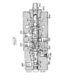
- a highly preferred embodiment of the valve 20 is illustrated.
- the same includes a va-ve body 100 provided with an internal bore 102.
- a spool 104 is reciprocally received within the bore IC2.
- One end of the bore 102 terminates in an enlarged diameter section 106 into which an end 108 of the spool 104 extends to mount a shoulder 110.
- a coil spring 112 is received within the enlarged diameter section 106 and abuts the shoulder 110.
- the coil spring 112 is retained in place by a threaded plug 114 which serves as a retainer for the spring 112 as well as a closure for the enlarged diameter section 106.
- a port 116 extends from a side of the body 100 to the enlarged diameter section 106 and will be connected to the output of the main pump of the system.
- the spring 112 serves to urge the spool 104 toward the left.
- a similar urging force may be applied against the spool 104 by the application of pump pressure to the end 108 of the spool through the port 116.
- the spool 104 contains a land 118 immediately adjacent to the end 108 in sealinq engaqement with the bore 102.
- the body 100 includes a furter port 120 in fluid communication with the bore 102.
- the port 120 will be connected to constant pressure source, for example, a pilot pump.
- the spool 104 includes an annulus 122 which is normally aligned with the port 120, as illustrated in Figs. 3 and 4, and immediately to the left thereof, as viewed in Figs. 3 and 4, is a land 124 provided on both sides with metering slots 126.
- the bore 102 is provided with an annulus 128 in the vicinity of the land 124 and a port 130 in the body 100 extends to the annulus 128.
- the port 130 When the valve is utilized as a supply margin valve as, for example, in the circuit illustrated in Fiq. 1, the port 130 will be connected to the control 12 of the pump 10. Conversely, when the valve is used as a demand margin valve as, for example, in the circuit illustrated in Fiq. 2, the port 130 will be connected to the pilot valve 50.
- t'ie right-hand metering slots 126 in the land 124 will establish varying degrees of fluid communication between the port 120 and the port 130 or, in some instances, block fluid communication between those ports.
- an additional port 132 is disposed in the body 100 just left of the port 130 and the port 132 will normally be connected to dr ⁇ in.
- the port 132 extends to an elongated chamber 134 within the body 100 which, as seen in Fig. 3, opens to both sides of the body 100 as at 136.
- Caps 138 are employed to close the chamber 134 so that all fluid received therein will be directed to the port 132 and to drain.
- the left-hand end of the spool 104 is tapered as at 140 and is disposed in a continuation 142 of the bore 102.
- a radially inwardly directed shoulder 144 separating the continuation 142 from the main part of the bore 102 serves to prevent fluid communication between the chamber 134 and the continuation 142.
- the spool 104 mcunts a shoulder 146.
- the width of the shoulder 146 is considerably less than the left-to-right dimension of the chamber 134 so that the shoulder 146 may reciprocate therein along the longitudinal axis of the spool 104.
- lie shoulder 146 includes a central aperture 148 in which the spool 104 is received and the spool is further provided with a peripheral slot 150 for receipt of a snap or spring retainer ring 152, also received in a slot 154 in the aperture 148 of the shoulder 146.
- the snap ring 152 serves to prevent relative movement between the shoulder 146 and the spool 104 along tl.e longitudinal axis of the latter.
- the top to bottom dimension of the chamber 134 is sufficiently close to that of the shoulder 146 so as to prevent any substantial degree of rotation of the shoulder 146 about the longitudinal axis of the spool 104 within the chamber 134.
- the purpose of this construction will appear hereinafter.
- the plug 114 is removed and the spool 104 withdrawn to the right as viewed in the drawings such that the tapered end 140 is disposed within the chamber 134.
- the snap ring 152 followed by the shoulder 146 are then disposed on the tapered end 140 with the taper serving to cam the snap ring 152 radially outwardly against its inherent resilience.
- the spool 104 is then shifted to the left until the snap ring 152 lodges within the slot 150 to firmly affix the shoulder 146 to the spool 104.
- the plugs 138 may then be installed along with the spring 112 and the plug 114.
- the body 100 includes a port 160 in fluid communication with the continnation 142 of the bore 102.
- the port 160 will typically be connected to the junction of the load or loads and their main control valves, such as the valves 16 or 44 shown in Figs. 1 and 2.
- the end 140 of the spool 104 acts as a pressure responsive surface acting in bucking relation to the surface at the end 108 and the spring force applied by the spring 112.
- the body 100 includes a pair of piston bores 162 which are parallel to the bore 102 and which extend from an end 164 of the body 100 to the chamber 134.
- Pistons 166 are disposed in the piston bores 162, which are located on opposite sides of the bore 104 for equalization purposes, and abuts the shoulder 146.
- an additional force may be applied to the spool 104 in bucking relation to that provided by the spring 112 and any fluid under pressure admitted to the port 116.
- the dimensioning of the chamber 134 as mentioned previously, to prevent rotation of the shoulder 146 ensures that the shoulder 146 cannot rotate out of contact with the pistons 166.
- the body 100 includes a feedback passage 170 connected to the annulus 128 to thereby be in fluid communication with the port 130.
- An end cap 172 is secured to the end 164 of the body 100 which is in fluid communication with the passage 170.
- a seal 178 is employed to seal the interface of the end cap 172 in the body 100 about the passages 170 and 176.
- the passage 176 opens to a bore 180 near the end cap which is normally closed, at one end, by a plug 182. From the bore 180, bores 184 establish fluid communication to the piston bores 162. The interface of the bores 162 and the bores 184 are sealed by seals 186.
- the structure is completed by the provision of a small bleed passage 190 extending from the feedback passage 170 to the chamber 134 to provide a restricted flow outlet for fluid outlet for fluid trapped against the pistons 166 in the bores 162 to drain.
- Operation of the valve is essentially the sane whether utilizeß as a supply margin valve or as a demand margin valve and in the configuration illustrated, when used as a sup f ly margin valve, is specifically intended for use with a pump of the type that will increase its output pressure in response to a decrease in signal pressure.
- both pump pressure and spring pressure will be tending to urge the spool 104 to the left, as viewed in the drawings, to thereby increase flow from the port 120 to the port 130 and increase pressure in the port 130.
- the load pressure which normally will be less than the pump pressure, will be applied to the end 140 of the spool 104 to urge the same to the right.
- the pressure at the port 130 will be applied to the pistons 166 to move the spool 104 to the right.
- the increasing force applied to the right-hand end of the spool 104 will result in a slight shifting of the spool 104 to the left thereby increasing the flow path from the port 120 to the pump 130 to decrease the area through the metering slots 126 and provide a higher fluid pressure to the control 12 for the pump 10 to thereby cause the same to decrease its output pressure.
- the resulting increase in pressure at the port 130 will be fed via the feedback passage 170 to the pistons 166 to increase the pressure tending to shift the spool 104 to the right to halt leftward movement and provide stability to prevent the spool 104 from chattering.
- the load pressure acting on the end 140 of the spool 104 along with the feedback pressure acting through the pistons 166 will tend to move the spool 104 to the right.
- the flow path from the port 120 to the port 130 will be narrowed, causing a decrease in pressure in the port 130 and a decrease in the pressure applied to the control of the pump 112 thereby commanding the same to increase its output pressure.
- the decrease in pressure at the port 130 will result in a lesser total pressure being exerted against the spool 104 by the pistons 166 to terminate such movement and at the same time prevent chattering and valve instability.
- the effective pressure responsive surface at the end 108 will be equal to that at the end 140.
- the pressure responsive surface of the pistons 166 will typically be equal in effective size to the effective size of the end 108 or the end 140. If the pressure applied by the spring 112 is then selected to be equal to the lowest pressure of the regulation spread of the pump control 12, the regulation spread being that range of pressures whose minimum and maximum values, when applied to the pump control 12,will cause the pump to change between maximum stroke and minimum stroke, or vice versa, then the ratio of the area of the end 108 to the total effective areas of the end 140 and the pistons 166 will be as the ratio of the regulation spread to the margin. With this situation, the margin will then be equal to approximately twice the regulation spread of the pump control 12.
- a valve made according to the invention is illustrated in Fig. 5 and is seen to include a valve body 300.
- the body is provided with a bore 302 which slidably receives a snool 304.
- One end of the bore 302 includes an enlargement 306 which opens to the exterior of the body and is tapped to receive a plug 308.
- the pluq 308 includes a piston bore 310 receiving a piston 312 and is also tapped so as to receive a fitting 314.
- the fitting 314 is adapted to be connected to the pump discharge as, for example, by the line 22 (Fig. 1) or the line 60 (Fig. 2) so that pump discharge pressure may be applied to the piston 312 which, in turn, abuts the right-hand end of the spool 304 to provide a biasing force thereagainst.
- the right-hand end of the spool 304 is also provided with a shoulder 316 and a spring 318 is interposed between the shoulder 316 and the plug 308. Consequently, the spring 318 applies a leftward biasing force to the spool 304 in concert with any force applied to the spool 304 by the piston 312.
- a port 320 opens to the bore 302 and is adapted to be connected to the pilot pump.
- a port 322 opens to the bore 302 in spaced relation to the port 320 and is adapted to be connected to the pump control 12 when the valve is used as a supply margin valve or to the pilot valve 50 when the valve is used as a demand margin valve.
- a further port 324 opens to the here 302 and is spaced from both ports 320 and 322 and is connected to drain.
- An end cap 326 is suitably secured by means (not shown) to the left-hand side of the body 30 and seals are utilized where indicated.
- the end cap 326 includes a stepped bore 328 having a first diameter 330 and a second diameter 332. As illustrated in the drawings, the diameter 320 is lesser than the diameter 332.
- a port 334 extends to the diameter 330 and is adapted to be connected to the system load as, for example, by either the line 24 (Fig. 1) or the line 62 (Fig. 2).
- a second port 336 is in fluid communication with the second diameter 332 and is plugged by a plug 338.
- a stepped piston 340 is received within the bore 328 and includes an end 342 which seals against the first diameter 330 and which may be subjected to fluid under pressure applied thereto via the port 334.
- the stepped piston 340 includes a shoulder 344 which sealingly, slidingly engages the second diameter 332 and which may be subjected to fluid pressure at the port 336.
- the stepped piston 340 further abuts the left-hand end of the spool 304 so that fluid under pressure, applied either to the end 342 or to the shoulder 344, or both, will provide a riqhtward biasing force to the spool 304.
- the same includes a groove 350, nominally aligned with the port 320 ard a groove 352 nominally aligned with the port 324.
- Lands 354 are located in the vicinity of the port 322 and it will be appreciated that as the spool 304 moves to the left, fluid communication from the port 320 to the port 322 will become established in varyin q degrees while fluid communication between the port 322 and the port 324 will be cut off in varying degrees. Riqhtward movement of the spool 304 will produce the opposite action and, as those skilled in the art will appreciate, the lands 354 serve to meter flow.
- the interior of the spool is hollow as at 356 and a cunduit 358 extends from the hollow center 356 toward the left-hand end of the bore 302 to be in fluid communication with the riqht-hand side of the shoulder 344.
- a radial port 360 adjacent to the right-hand end of the spool 304 is in fluid communication with the enlargement 306 and with the hollow center 356 of the spool and a similar radial port 362 extends from the center of the spool to the groove 352.
- a feedback passage 364 extends from the port 322 to the port 336 to complete the essential details of the valve illustrated in Fig. 5.
- the effective area of the piston 312 subjected to pump discharge pressure will be equal to the effective area of the end 342 of the stepped piston 340 subjected to load pressure.
- the effective area of the shoulder 344 will be equal to both.
- the spring 318 may be selected to provide a pressure equal to tne pressure at the lower end of the regulation spread utilized.
- valve as a supply margin valve with a pump of the type that will increase its output pressure in response to an increase in signal pressure, it is only necessary in either version to interchange the pump and load signals so that the pump signal opposes the spring force and the load signal adds to the spring force, and aujust the level of spring force to fit the new condition.
- valves made according to the invention provide excellent stability, thereby allowing fine control over loads in the systems in which the valves are utilized.
Landscapes
- Engineering & Computer Science (AREA)
- Physics & Mathematics (AREA)
- Fluid Mechanics (AREA)
- Mechanical Engineering (AREA)
- General Engineering & Computer Science (AREA)
- Fluid-Pressure Circuits (AREA)
- Multiple-Way Valves (AREA)
Applications Claiming Priority (2)
| Application Number | Priority Date | Filing Date | Title |
|---|---|---|---|
| US901409 | 1978-05-01 | ||
| US05/901,409 US4196588A (en) | 1978-05-01 | 1978-05-01 | Margin valve |
Publications (3)
| Publication Number | Publication Date |
|---|---|
| EP0005151A2 true EP0005151A2 (de) | 1979-11-14 |
| EP0005151A3 EP0005151A3 (en) | 1979-11-28 |
| EP0005151B1 EP0005151B1 (de) | 1984-02-15 |
Family
ID=25414117
Family Applications (1)
| Application Number | Title | Priority Date | Filing Date |
|---|---|---|---|
| EP19790100593 Expired EP0005151B1 (de) | 1978-05-01 | 1979-02-28 | Hydraulisches System mit einem Anforderungsgrenzventil |
Country Status (5)
| Country | Link |
|---|---|
| US (1) | US4196588A (de) |
| EP (1) | EP0005151B1 (de) |
| JP (1) | JPS54144564A (de) |
| CA (1) | CA1116496A (de) |
| DE (1) | DE2966651D1 (de) |
Cited By (2)
| Publication number | Priority date | Publication date | Assignee | Title |
|---|---|---|---|---|
| EP0465655A4 (en) * | 1989-10-11 | 1992-03-04 | Hitachi Construction Machinery Co., Ltd. | Hydraulic driving apparatus of civil engineering/construction equipment |
| CN110439876A (zh) * | 2019-09-04 | 2019-11-12 | 辽宁工程技术大学 | 一种适用于摇臂机构的数字液压缸 |
Families Citing this family (11)
| Publication number | Priority date | Publication date | Assignee | Title |
|---|---|---|---|---|
| US4401009A (en) * | 1972-11-08 | 1983-08-30 | Control Concepts, Inc. | Closed center programmed valve system with load sense |
| US4648803A (en) * | 1985-09-17 | 1987-03-10 | Deere & Company | Control circuit and control valve for radial piston pump |
| US5249421A (en) * | 1992-01-13 | 1993-10-05 | Caterpillar Inc. | Hydraulic control apparatus with mode selection |
| US5680806A (en) * | 1996-08-23 | 1997-10-28 | Henry; Michael F. | Compressible fluid flow control valve and constant speed pneumatic motor application therefor |
| JP4067596B2 (ja) * | 1997-03-07 | 2008-03-26 | 日立建機株式会社 | 建設機械の油圧制御装置 |
| US6033188A (en) * | 1998-02-27 | 2000-03-07 | Sauer Inc. | Means and method for varying margin pressure as a function of pump displacement in a pump with load sensing control |
| US6030183A (en) * | 1998-04-30 | 2000-02-29 | Caterpillar Inc. | Variable margin pressure control |
| DE102011084932B4 (de) * | 2011-10-21 | 2025-01-23 | Zf Friedrichshafen Ag | Ventilvorrichtung mit einem mehrere Schaltzungen aufweisenden Ventilgehäuse |
| GB2501486A (en) * | 2012-04-24 | 2013-10-30 | Jc Bamford Excavators Ltd | Work machine having a hydraulic system comprising variable orifice ratios |
| CN109826984B (zh) * | 2019-04-01 | 2024-05-24 | 浙江中煤机械科技有限公司 | 一种先导式安全阀 |
| US12442396B2 (en) * | 2020-01-27 | 2025-10-14 | Parker-Hannifin Corporation | Valve with an adjustable flow sharing pressure compensator |
Family Cites Families (15)
| Publication number | Priority date | Publication date | Assignee | Title |
|---|---|---|---|---|
| US2713772A (en) * | 1952-10-16 | 1955-07-26 | Cincinnati Milling Machine Co | Hydraulic transmission and control for machine tool tables |
| US3260273A (en) * | 1960-04-04 | 1966-07-12 | Sanders Associates Inc | Motor valve having differential pressure feedback |
| US3484960A (en) * | 1967-08-31 | 1969-12-23 | Sandvikens Jernverks Ab | Apparatus for controlling the position of the elevator in a self-loading elevator scraper |
| US3543508A (en) * | 1968-10-16 | 1970-12-01 | Hyster Co | Hydrostatic transmission with pressure control |
| BE794115A (fr) * | 1971-03-24 | 1973-05-16 | Caterpillar Tractor Co | Dispositif de valve sommatrice |
| US3830594A (en) * | 1971-06-28 | 1974-08-20 | Caterpillar Tractor Co | Variable displacement pump having pressure compensator control method |
| US3898807A (en) * | 1974-06-20 | 1975-08-12 | Caterpillar Tractor Co | Hydrostatic transmission control system |
| US3945764A (en) * | 1974-09-05 | 1976-03-23 | Parker-Hannifin Corporation | Variable displacement pump control assembly |
| JPS5221149A (en) * | 1975-08-11 | 1977-02-17 | Kubota Ltd | Combine |
| US3987623A (en) * | 1976-01-23 | 1976-10-26 | Caterpillar Tractor Co. | Controlled priority fluid system of a crawler type vehicle |
| US4028890A (en) * | 1976-01-23 | 1977-06-14 | Caterpillar Tractor Co. | Piston pump assembly utilizing load pressure control |
| US3987622A (en) * | 1976-02-02 | 1976-10-26 | Caterpillar Tractor Co. | Load controlled fluid system having parallel work elements |
| JPS602521B2 (ja) * | 1976-06-11 | 1985-01-22 | ダイキン工業株式会社 | 流体装置 |
| US4074529A (en) * | 1977-01-04 | 1978-02-21 | Tadeusz Budzich | Load responsive system pump controls |
| JPS53122103A (en) * | 1977-03-31 | 1978-10-25 | Komatsu Ltd | Liquid pressure equipment |
-
1978
- 1978-05-01 US US05/901,409 patent/US4196588A/en not_active Expired - Lifetime
-
1979
- 1979-02-28 DE DE7979100593T patent/DE2966651D1/de not_active Expired
- 1979-02-28 EP EP19790100593 patent/EP0005151B1/de not_active Expired
- 1979-04-18 JP JP4782979A patent/JPS54144564A/ja active Pending
- 1979-04-30 CA CA000326680A patent/CA1116496A/en not_active Expired
Cited By (3)
| Publication number | Priority date | Publication date | Assignee | Title |
|---|---|---|---|---|
| EP0465655A4 (en) * | 1989-10-11 | 1992-03-04 | Hitachi Construction Machinery Co., Ltd. | Hydraulic driving apparatus of civil engineering/construction equipment |
| CN110439876A (zh) * | 2019-09-04 | 2019-11-12 | 辽宁工程技术大学 | 一种适用于摇臂机构的数字液压缸 |
| CN110439876B (zh) * | 2019-09-04 | 2024-05-17 | 辽宁工程技术大学 | 一种适用于摇臂机构的数字液压缸 |
Also Published As
| Publication number | Publication date |
|---|---|
| DE2966651D1 (en) | 1984-03-22 |
| US4196588A (en) | 1980-04-08 |
| EP0005151B1 (de) | 1984-02-15 |
| JPS54144564A (en) | 1979-11-10 |
| EP0005151A3 (en) | 1979-11-28 |
| CA1116496A (en) | 1982-01-19 |
Similar Documents
| Publication | Publication Date | Title |
|---|---|---|
| US3455210A (en) | Adjustable,metered,directional flow control arrangement | |
| US4196588A (en) | Margin valve | |
| US5715865A (en) | Pressure compensating hydraulic control valve system | |
| US4736770A (en) | Hydraulic distributor of the proportional type, with load sensing of the highest pressures in the operating circuits | |
| US4593715A (en) | Hydraulic controllable two-port valve for a liquid stream | |
| US3613717A (en) | Remote electrically modulated relief valve | |
| US4159724A (en) | Load responsive control valve | |
| US4204459A (en) | Combination check and flow control valve for hydraulic systems | |
| US4688600A (en) | Multiway valve with pressure balance | |
| US4313468A (en) | Servo valve | |
| CA1195206A (en) | Electrohydraulic valve | |
| US6098403A (en) | Hydraulic control valve system with pressure compensator | |
| US3973580A (en) | Flow divider valve | |
| CA1251353A (en) | Control circuit and control valve for radial piston pump | |
| US3985153A (en) | Pressure compensating valve spool assembly for a hydraulic control valve | |
| US3983893A (en) | Flow divider valve assembly | |
| DE2616251C2 (de) | Druckbegrenzungs- und Nachsaugventil | |
| US4033236A (en) | All hydraulic motor grader circuitry | |
| US4463660A (en) | Multi-way valve | |
| US4325410A (en) | Control device for a hydraulically operated load | |
| US4135541A (en) | Pressure relief and load check valve assembly | |
| CA1316074C (en) | Pressure regulator valve | |
| US3861145A (en) | Multiple hydraulic control circuits with pressure compensated flow control and a single variable delivery pump | |
| US4085920A (en) | Pilot control valve with servo means | |
| US3999892A (en) | Interconnected pump control means of a plurality of pumps |
Legal Events
| Date | Code | Title | Description |
|---|---|---|---|
| PUAI | Public reference made under article 153(3) epc to a published international application that has entered the european phase |
Free format text: ORIGINAL CODE: 0009012 |
|
| PUAL | Search report despatched |
Free format text: ORIGINAL CODE: 0009013 |
|
| AK | Designated contracting states |
Designated state(s): BE CH DE FR GB IT LU NL SE |
|
| AK | Designated contracting states |
Designated state(s): BE CH DE FR GB IT LU NL SE |
|
| 17P | Request for examination filed | ||
| ITF | It: translation for a ep patent filed | ||
| GRAA | (expected) grant |
Free format text: ORIGINAL CODE: 0009210 |
|
| AK | Designated contracting states |
Designated state(s): BE CH DE FR GB IT LU NL SE |
|
| PG25 | Lapsed in a contracting state [announced via postgrant information from national office to epo] |
Ref country code: SE Effective date: 19840215 Ref country code: NL Effective date: 19840215 Ref country code: CH Effective date: 19840215 |
|
| PG25 | Lapsed in a contracting state [announced via postgrant information from national office to epo] |
Ref country code: LU Free format text: LAPSE BECAUSE OF NON-PAYMENT OF DUE FEES Effective date: 19840229 |
|
| REF | Corresponds to: |
Ref document number: 2966651 Country of ref document: DE Date of ref document: 19840322 |
|
| ET | Fr: translation filed | ||
| REG | Reference to a national code |
Ref country code: CH Ref legal event code: PL |
|
| NLV1 | Nl: lapsed or annulled due to failure to fulfill the requirements of art. 29p and 29m of the patents act | ||
| PGFP | Annual fee paid to national office [announced via postgrant information from national office to epo] |
Ref country code: FR Payment date: 19841205 Year of fee payment: 7 |
|
| PGFP | Annual fee paid to national office [announced via postgrant information from national office to epo] |
Ref country code: DE Payment date: 19841211 Year of fee payment: 7 |
|
| PLBE | No opposition filed within time limit |
Free format text: ORIGINAL CODE: 0009261 |
|
| STAA | Information on the status of an ep patent application or granted ep patent |
Free format text: STATUS: NO OPPOSITION FILED WITHIN TIME LIMIT |
|
| BECH | Be: change of holder |
Free format text: 840215 *CATERPILLAR INC. |
|
| PGFP | Annual fee paid to national office [announced via postgrant information from national office to epo] |
Ref country code: BE Payment date: 19841231 Year of fee payment: 7 |
|
| 26N | No opposition filed | ||
| REG | Reference to a national code |
Ref country code: GB Ref legal event code: 732 |
|
| ITPR | It: changes in ownership of a european patent |
Owner name: CESSIONE;CATERPILLAR INC. |
|
| REG | Reference to a national code |
Ref country code: FR Ref legal event code: TP |
|
| BERE | Be: lapsed |
Owner name: CATERPILLAR INC. Effective date: 19880228 |
|
| PG25 | Lapsed in a contracting state [announced via postgrant information from national office to epo] |
Ref country code: FR Free format text: LAPSE BECAUSE OF NON-PAYMENT OF DUE FEES Effective date: 19881028 |
|
| PG25 | Lapsed in a contracting state [announced via postgrant information from national office to epo] |
Ref country code: DE Effective date: 19881101 |
|
| GBPC | Gb: european patent ceased through non-payment of renewal fee | ||
| PG25 | Lapsed in a contracting state [announced via postgrant information from national office to epo] |
Ref country code: GB Free format text: LAPSE BECAUSE OF NON-PAYMENT OF DUE FEES Effective date: 19881118 |
|
| REG | Reference to a national code |
Ref country code: FR Ref legal event code: ST |
|
| PG25 | Lapsed in a contracting state [announced via postgrant information from national office to epo] |
Ref country code: BE Effective date: 19890228 |