EP0005436A1 - Installation de surveillance avec indicateur centralisé des états de fonctionnement d'un véhicule automobile - Google Patents
Installation de surveillance avec indicateur centralisé des états de fonctionnement d'un véhicule automobile Download PDFInfo
- Publication number
- EP0005436A1 EP0005436A1 EP79100791A EP79100791A EP0005436A1 EP 0005436 A1 EP0005436 A1 EP 0005436A1 EP 79100791 A EP79100791 A EP 79100791A EP 79100791 A EP79100791 A EP 79100791A EP 0005436 A1 EP0005436 A1 EP 0005436A1
- Authority
- EP
- European Patent Office
- Prior art keywords
- display
- operating states
- monitoring device
- displayed
- warning device
- Prior art date
- Legal status (The legal status is an assumption and is not a legal conclusion. Google has not performed a legal analysis and makes no representation as to the accuracy of the status listed.)
- Granted
Links
Images


Classifications
-
- G—PHYSICS
- G07—CHECKING-DEVICES
- G07C—TIME OR ATTENDANCE REGISTERS; REGISTERING OR INDICATING THE WORKING OF MACHINES; GENERATING RANDOM NUMBERS; VOTING OR LOTTERY APPARATUS; ARRANGEMENTS, SYSTEMS OR APPARATUS FOR CHECKING NOT PROVIDED FOR ELSEWHERE
- G07C5/00—Registering or indicating the working of vehicles
- G07C5/08—Registering or indicating performance data other than driving, working, idle, or waiting time, with or without registering driving, working, idle or waiting time
- G07C5/0816—Indicating performance data, e.g. occurrence of a malfunction
Definitions
- the invention relates to a warning device with a central display of operating states to be monitored in motor vehicles, with a display device which can be controlled by an operation monitoring device.
- the known warning device includes a central warning lamp that flashes or burns continuously depending on the importance of the critical operating state that occurs, and a group of individual lamps that are each assigned to an operating state that is to be monitored and that also emerge depending on the urgency when such a critical operating state occurs the display flashes or burns continuously.
- the warning device includes an operational monitoring device in which the information to be displayed is classified according to its urgency or according to the priority of the display and, if necessary, with a desired signal delay for displaying the drop in certain liquid levels, such as erem liquid, cooling water level and windscreen washer water level, cause the display.
- the operation monitoring device also performs certain functions, for example to measure the engine oil level only when it is at a standstill.
- the classification is carried out according to the prior art, for example, in such a way that the group of the most important priority includes the oil pressure, the oil level, brake circuit failure and brake fluid, while in a second group information about the brake pad, the hand brake, the cooling water level, the The temperature of the cooling water, the tank reserve, the windscreen washer fluid level, the brake light and the tail light are all arranged.
- the known warning device includes an acknowledgment button which is connected to the operation monitoring device and which is arranged, for example, in the console of the motor vehicle and with which a warning about a critical operating state that is displayed can be acknowledged.
- the acknowledge button for example, the blinking of the central warning light is converted into a continuous burning or the continuous burning of the warning light is switched off when a lower priority fault occurs.
- the individual lights which are assigned to the disrupted operating states to be displayed continue to flash, and the individual lights which are assigned to the disrupted operating states of the lower priority continue to burn, memories which are fed with signals from the operating monitoring device taking effect.
- the present invention has for its object to avoid the disadvantages of the known warning device with a central display to make the display so that as little additional space as possible in the driver's good field of vision is required on the dashboard console, so that the greatest possible guarantee for the striking one indicated critical operating state is given.
- This arrangement of the display should be associated with as little additional effort as possible in order to be able to use the warning device desired for safety reasons to the greatest extent possible.
- the display device is arranged in an analog time clock, the dial of which is translucent in several places with the names of the monitored operating states affixed at these points, which names appear when the lighting of the operation monitoring device can be controlled by the operation monitoring device Lift translucent places from the back of the dial visibly from their surroundings so that the information to be displayed about the operating status can be read from the dial.
- the surface of the dial of an analog time clock which is normally not used for display purposes, is used to represent the operating states in which the driver is to be warned, without this having to hinder the analog display of the time.
- the operating states the occurrence of which is to be warned to the driver, can be represented both by a literal description of the operating states and by a symbolic representation using so-called pictograms.
- the translucent but not transparent surface of the dial which has the corresponding representation of the operating state, can be illuminated from the back of the dial by a light source, for example by a group of light-emitting diodes. When the light source is switched off, the driver is shown in light from the front not visible.
- the translucent areas on the back of the dial can be illuminated both continuously and intermittently for special emphasis.
- a variant of the warning device according to the invention has the features that the display device is designed as a display which is arranged in the dial of an analog time clock which can be controlled by the operation monitoring device to display the names of the operating states to be displayed.
- the space required to display the monitored operating state on the dial is used particularly well, since the individual operating states are not to be displayed at different points, but are made visible at one and the same point by actuating the display.
- the display can be designed as a dot matrix or can be constructed with liquid crystals.
- a particularly advantageous variant of the display device according to the invention is characterized in that the display display of a digital time clock is used as the display device, which is coupled to the operation monitoring device and can be controlled by it to display the designation of the operating states to be displayed, such that the operating states to be displayed are of greater importance
- the time display disappears and the name of the function is shown instead.
- the display which is present anyway for displaying the time is advantageously used several times in order to also display the operating states to be monitored.
- the operational monitoring device is switched in such a way that operating states of a high priority level are preferably displayed, the time disappearing during a predetermined period of time or until acknowledgment.
- the display display has a number of fields equal to the number of priority groups and that the operating states of each field are in one field assigned priority group can be represented.
- This warning device has the advantage that the operating states of the highest priority are represented in one field and the operating states of the next lower priority are unhindered in a second field by the representation of the critical operating states of higher priority.
- the least important operating states to be monitored can be displayed in a third field. This arrangement of the fields also improves the clarity of the importance of the disturbed operating state.
- the display is set up to show the operating state a: .s pictorial representation (pictogram).
- warning device A further development of the warning device is that a query unit comprising a keyboard is connected to the display and / or the operational monitoring device for selecting the functions to be monitored.
- functions of lower priority to be monitored can be selected with the keyboard in order to determine successively by operating the keyboard whether the corresponding operating states are present or not.
- the display can take place either in the display provided for displaying the time or in a separate display field within the clock.
- the warning device can advantageously have the feature that the display and / or the operational monitoring device is provided with a program memory for coding the name to be displayed in one of several predetermined languages.
- the part of the stored program that includes the naming of the operating states in the desired language is activated. Switching can be done either by a program switch or by a program card programmed for the respective language.
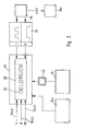
- groups of sensors are shown, which are assigned to the engine, the lighting, the chassis and the body.
- the transmitters provide information about the operating states to be monitored as discrete signals - J-Mein signals - as analog signals, for example depending on resistance transmitters, or as a frequency.
- Functions of the engine to be monitored are, for example, oil pressure, oil level, oil temperature, cooling water level, cooling water temperature, fuel consumption, engine speed, top dead center and exhaust gas values.
- Functions of the lighting to be monitored are brake light, tail light, license plate light, parking light, driving light, high beam, fog light.
- the functions of the chassis to be monitored include considering brake circuit pressure, brake pads brake fluid level, hand brake, speed, anti-lock braking system.
- the bodywork includes the functions to be overwhelmed, tank reserve, inside temperature, outside temperature, windscreen washer fluid level, heated rear log: and door contact switch.
- the operating Monitoring device comprises the microprocessor, the memory for address coding, a time and clock generator, an analog-digital converter for converting the signals of the input stage into digitally processable information, a display controller for controlling the display means (not shown in FIG. 2) and a character generator for a dot matrix as a display or a display display built up with liquid crystals.
- the operating states to be displayed are classified in priority levels I, II, III and output as individual functions of the operating states in the classified blocks 7, B, 9.
- functions of three priorities linked in the classified blocks 10, 11, 12 are formed from the information provided by the sensor groups 1 to 4.
- Block 10 includes, for example, the linked information about oil pressure, oil temperature and speed as well as about the speed.
- the gear selection and ignition timing are to be classified in the block of priority II.
- the lowest priority block 12 includes information about average fuel consumption, current fuel consumption, acceleration, deceleration and stored speed.
- the operation monitoring device is operated in time-division multiplex operation, so that the signals of the information relating to blocks 7 to 12 are emitted in rapid succession and repetition at an output stage 13 of the operation monitoring device.
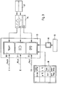
- 20 is a dot matrix as a display of a digital time clock 21.
- the dot matrix is fed via lines 14ab, 15ab, 16ab from the operational monitoring device 6 in FIG. 1, in such a way that, instead of the time in the event of a warning, the operational states of the priority levels I, II can appear as lettering. Instead of the time, only one operating status is displayed in the event of a warning or on request in a manner to be described.
- the display on request is carried out by actuating a query button 23.
- This query button is arranged with a first control device 24, which can be integrated in the operational monitoring device, in the circuit arrangement in such a way that the information of priority level III is displayed serially, including the time, by pressing the query button become.
- an operating state of priority groups I and II is automatically represented by the structure of the operational monitoring device instead of the otherwise permanently displayed time.
- the sequence control can take place in such a way that the time is permanently displayed as long as there is no warning and no query with the query key 23.
- a second control device 25 which can all be a component of the operational monitoring device, displays the information about operating states of priority group I as a flashing lettering, while the information about 3 operating states of priority group II is displayed as a permanently lit lettering in the event of a warning.
- a third control device 26 which is also part of the brake monitoring device device, it is ensured that the operating status or error of the highest priority is displayed.
- a variant of the third control device 26a can also be used to control a plurality of operating states to be displayed in the event of a warning in such a way that the operating states are displayed one after the other, although the priority of the errors can no longer be recognized easily.
- the warning device comprises a display with three fields 30, 31, 32, which are embedded in the dial of a clock 33. Each field is also built up with a dot matrix.
- the operational monitoring device which is connected to field 30 via lines 14ab, is coupled to field 31 via line 15ab and is connected to field 32 via line 16ab, comprises a character generator for pictograms which represent the symbols of the operating states, for example one Oil can for the oil pressure, a headlight for high beam and a heating coil for the heated rear window.
- a fourth control device 34 which can also be part of the operation monitoring device, controls the display of the operating states of priority group I as a flashing pictogram.
- the operating states of priority group II are also shown as flashing pictograms, but with a different ratio of the lighting duration to the pause.
- the operating states of priority group III are displayed continuously.
- a button 35 is provided in connection with a fifth control device 36, which may also belong to the operational monitoring device.
- the fifth control device is switched in such a way that the information about the operating states of priority group III is displayed in succession at the push of a button, the time of day being permanently displayed after every five seconds.
- a query unit with a keyboard 38 can also be provided, which has a number of buttons corresponding to the number of possible information items of the priority group III, on each of which a pictogram or an abbreviation of the operating state that is shown at its presence is displayed in the field 32 when the associated key is pressed. By tapping the button, it can be determined, for example, what the average fuel consumption is at the moment or how high the internal temperature in the motor vehicle is at the time.
- the sixth control device 37 takes effect, which ensures a successive, continuous display of the operating states in the fields 30 and 31.
- a display with three fields 41, 42, 43 is embedded in the dial 40 of a watch.
- the fields 41 and 42 which are set up to display the information about the operating states of the priority groups I and II as lettering, each include a display area 44 and 45 for the lettering, a luminous surface 46 or 47 for signaling a fault and a numerical surface 48 or 49 for displaying the number of operating states or faults to be displayed simultaneously.
- the field 43 is only set up as a display area for displaying the operating state of priority group III.
- the operating states of priority group III are represented by a query unit 38 with buttons corresponding to the execution of the query unit in the warning device according to FIG. 3 or by a button 35 with a fifth control device 36 according to FIG. 3.
- the display of the operating status in priority group I is carried out in such a way that the lettering illuminates continuously while the left illuminated surface 46 flashes.
- Operating states of priority group II are displayed in such a way that the luminous surface 47 and the lettering light up continuously.
- the operating states of priority group III are also continuously illuminated until a new query is made or the time of day is permanently displayed after a predetermined time of, for example, five seconds, the latter operating mode occurring when the button 35 is pressed.
- an eighth control device 51 flashes the lettering, which continuously indicates the existing errors or operating states to be signaled.
- the left illuminated area flashes there at, while the right-hand dial 48 permanently shows the number of errors.
- the lettering for the representation of the operating states also flashes, with a continuous display of all operating states to be signaled.
- the left illuminated surface 47 illuminates permanently and the right numerical surface 49 also permanently displays a number of errors.
- FIG. 4 also shows a program memory 52 which is connected to the display and the operational monitoring device and contains a programming of the words representing the operating states in several languages for display in German, English, French and Spanish.
- the operating status is optionally displayed in one of the languages mentioned.
Landscapes
- Physics & Mathematics (AREA)
- General Physics & Mathematics (AREA)
- Instrument Panels (AREA)
- Alarm Systems (AREA)
- Testing And Monitoring For Control Systems (AREA)
Applications Claiming Priority (2)
| Application Number | Priority Date | Filing Date | Title |
|---|---|---|---|
| DE2821344 | 1978-05-16 | ||
| DE19782821344 DE2821344A1 (de) | 1978-05-16 | 1978-05-16 | Warneinrichtung mit zentraler anzeige zu ueberwachender betriebszustaende in kraftfahrzeugen |
Publications (2)
| Publication Number | Publication Date |
|---|---|
| EP0005436A1 true EP0005436A1 (fr) | 1979-11-28 |
| EP0005436B1 EP0005436B1 (fr) | 1981-11-04 |
Family
ID=6039485
Family Applications (1)
| Application Number | Title | Priority Date | Filing Date |
|---|---|---|---|
| EP79100791A Expired EP0005436B1 (fr) | 1978-05-16 | 1979-03-15 | Installation de surveillance avec indicateur centralisé des états de fonctionnement d'un véhicule automobile |
Country Status (3)
| Country | Link |
|---|---|
| US (1) | US4287504A (fr) |
| EP (1) | EP0005436B1 (fr) |
| DE (1) | DE2821344A1 (fr) |
Cited By (12)
| Publication number | Priority date | Publication date | Assignee | Title |
|---|---|---|---|---|
| EP0072000A3 (en) * | 1981-08-07 | 1984-04-18 | Nippondenso Co., Ltd. | Motor vehicle diagnostic monitoring system |
| WO1984002787A1 (fr) * | 1983-01-05 | 1984-07-19 | Towmotor Corp | Appareil d'affichage de diagnostic |
| WO1986001321A1 (fr) * | 1984-08-09 | 1986-02-27 | Robert Bosch Gmbh | Dispositif d'affichage de donnees et/ou de valeurs parametrques dans des vehiclues a moteur |
| EP0190429A1 (fr) * | 1985-01-09 | 1986-08-13 | VDO Adolf Schindling AG | Dispositif pour l'indication électronique de défauts, notamment d'une électronique de moteur d'automobiles |
| EP0374998A1 (fr) * | 1988-12-22 | 1990-06-27 | ACTIA Société Anonyme | Procédé et dispositif de diagnostic des défauts sur des boîtiers électriques ou électroniques embarqués sur véhicule automobile |
| EP0413931A1 (fr) * | 1989-08-24 | 1991-02-27 | Dr.Ing.h.c. F. Porsche Aktiengesellschaft | Calculateur de bord pour véhicules automobiles |
| US5081443A (en) * | 1987-06-02 | 1992-01-14 | Christoph Breit | Device for protecting the systems and load of motor vehicles |
| WO1992004693A1 (fr) * | 1990-09-07 | 1992-03-19 | Caterpillar Inc. | Affichage adaptatif pour vehicule |
| NL9400821A (nl) * | 1994-05-18 | 1996-01-02 | Orlaco Holding B V | Stelsel voor het visualiseren van systeemgrootheden in voertuigen. |
| WO1997046977A1 (fr) * | 1996-05-31 | 1997-12-11 | Daimler-Benz Aktiengesellschaft | Dispositif de signalisation |
| US6909407B1 (en) | 1998-09-16 | 2005-06-21 | Mannesmann Vdo Ag | Device and method for displaying pictograms in a vehicle |
| FR2977840A1 (fr) * | 2011-07-12 | 2013-01-18 | Faurecia Interieur Ind | Systeme d'affichage d'informations dans un vehicule |
Families Citing this family (21)
| Publication number | Priority date | Publication date | Assignee | Title |
|---|---|---|---|---|
| JPS5646423A (en) * | 1979-09-25 | 1981-04-27 | Nissan Motor Co Ltd | Multifunctional electronic meter for automobile |
| JPS56154750A (en) * | 1980-04-30 | 1981-11-30 | Toshiba Corp | Display device of copying machine |
| JPS5762944A (en) * | 1980-09-02 | 1982-04-16 | Honda Motor Co Ltd | Fail-saft device for sensors for detecting states and conditions of internal combustion engine |
| US4417231A (en) * | 1981-04-10 | 1983-11-22 | Watt Richard E | Engine over-temperature and oil pressure loss audible warning device |
| JPS57201735A (en) * | 1981-06-03 | 1982-12-10 | Nissan Motor Co Ltd | Display device for vehicle |
| IT1194058B (it) * | 1981-07-30 | 1988-09-14 | Fiat Auto Spa | Dispositivo per la visualizzazione selettiva a bordo di un autoveicolo di informazioni concernenti le condizioni di impiego dell autoveicolo stesso |
| EP0114821A1 (fr) * | 1982-07-14 | 1984-08-08 | MICHAEL, Shawky Shafeek | Coussinets de sabot de frein modifies |
| US4803646A (en) * | 1984-10-01 | 1989-02-07 | Ford Motor Company | Electronic odometer |
| US4710888A (en) * | 1984-10-01 | 1987-12-01 | Ford Motor Company | Electronic odometer |
| US4702753A (en) * | 1986-04-21 | 1987-10-27 | Thaddeus Kowalczyk | Air purifier-combination filter |
| US5293513A (en) * | 1990-05-30 | 1994-03-08 | Mitsubishi Denki Kabushiki Kaisha | Switching system for automotive vehicle including a reflector positioned below a sight line of a driver |
| JPH06201407A (ja) * | 1992-09-16 | 1994-07-19 | Caterpillar Inc | 診断システムにおいてセンサ出力を表示する方法および装置 |
| US5453939A (en) * | 1992-09-16 | 1995-09-26 | Caterpillar Inc. | Computerized diagnostic and monitoring system |
| DE19507997B4 (de) | 1995-03-07 | 2007-07-12 | Robert Bosch Gmbh | Verfahren zur Anzeige von mehreren Informationen |
| DE19707188A1 (de) * | 1997-02-22 | 1998-08-27 | Opel Adam Ag | Vorrichtung zur Information von Insassen eines Kraftfahrzeugs |
| DE19744910B4 (de) * | 1997-10-10 | 2004-07-22 | Volkswagen Ag | Warnsignalvorrichtung für elektrische Verbraucher in Kraftfahrzeugen |
| DE10046905A1 (de) * | 2000-09-21 | 2002-04-11 | Man Nutzfahrzeuge Ag | Verfahren zur Anzeige von Ereignissen in einem Kraftfahrzeug |
| DE10046907A1 (de) * | 2000-09-21 | 2002-04-11 | Man Nutzfahrzeuge Ag | Verfahren zur Anzeige von Ereignissen in einem Kraftfahrzeug |
| US6991605B2 (en) * | 2002-12-18 | 2006-01-31 | Siemens Medical Solutions Usa, Inc. | Three-dimensional pictograms for use with medical images |
| US9131548B2 (en) * | 2006-02-09 | 2015-09-08 | Production Resource Group, Llc | Test machine for an automated light |
| CA2697471C (fr) * | 2007-08-24 | 2014-05-20 | Paccar Inc | Gestion d'erreur pour affichage multifonction |
Citations (4)
| Publication number | Priority date | Publication date | Assignee | Title |
|---|---|---|---|---|
| DE2158788A1 (de) * | 1971-11-26 | 1973-06-07 | Messerschmitt Boelkow Blohm | Optische anzeige fuer ein kraftfahrzeug |
| FR2167141A5 (fr) * | 1971-12-29 | 1973-08-17 | Gen Motors Corp | |
| FR2197361A5 (fr) * | 1972-08-22 | 1974-03-22 | Vdo Schindling | |
| US3916375A (en) * | 1970-10-27 | 1975-10-28 | Nippon Denso Co | Centralized warning system for vehicles |
Family Cites Families (4)
| Publication number | Priority date | Publication date | Assignee | Title |
|---|---|---|---|---|
| GB451321A (en) * | 1934-11-19 | 1936-08-04 | Jaeger Ets Ed | Improved device for signalling defects in the operation of an internal combustion engine, particularly for motor cars |
| US4109235A (en) * | 1971-10-29 | 1978-08-22 | Regie Nationale Des Usines Renault | Electronic-display instrument panels for automotive vehicles |
| JPS5613618Y2 (fr) * | 1974-05-16 | 1981-03-30 | ||
| US3988730A (en) * | 1974-12-31 | 1976-10-26 | Motorola, Inc. | Multiple parameter monitoring and readout system with sampling of parameters of higher priority than the highest parameter which is out of tolerance |
-
1978
- 1978-05-16 DE DE19782821344 patent/DE2821344A1/de not_active Withdrawn
-
1979
- 1979-03-15 EP EP79100791A patent/EP0005436B1/fr not_active Expired
- 1979-06-07 US US06/046,598 patent/US4287504A/en not_active Expired - Lifetime
Patent Citations (4)
| Publication number | Priority date | Publication date | Assignee | Title |
|---|---|---|---|---|
| US3916375A (en) * | 1970-10-27 | 1975-10-28 | Nippon Denso Co | Centralized warning system for vehicles |
| DE2158788A1 (de) * | 1971-11-26 | 1973-06-07 | Messerschmitt Boelkow Blohm | Optische anzeige fuer ein kraftfahrzeug |
| FR2167141A5 (fr) * | 1971-12-29 | 1973-08-17 | Gen Motors Corp | |
| FR2197361A5 (fr) * | 1972-08-22 | 1974-03-22 | Vdo Schindling |
Cited By (19)
| Publication number | Priority date | Publication date | Assignee | Title |
|---|---|---|---|---|
| EP0072000A3 (en) * | 1981-08-07 | 1984-04-18 | Nippondenso Co., Ltd. | Motor vehicle diagnostic monitoring system |
| WO1984002787A1 (fr) * | 1983-01-05 | 1984-07-19 | Towmotor Corp | Appareil d'affichage de diagnostic |
| WO1986001321A1 (fr) * | 1984-08-09 | 1986-02-27 | Robert Bosch Gmbh | Dispositif d'affichage de donnees et/ou de valeurs parametrques dans des vehiclues a moteur |
| EP0190429A1 (fr) * | 1985-01-09 | 1986-08-13 | VDO Adolf Schindling AG | Dispositif pour l'indication électronique de défauts, notamment d'une électronique de moteur d'automobiles |
| US5081443A (en) * | 1987-06-02 | 1992-01-14 | Christoph Breit | Device for protecting the systems and load of motor vehicles |
| EP0374998A1 (fr) * | 1988-12-22 | 1990-06-27 | ACTIA Société Anonyme | Procédé et dispositif de diagnostic des défauts sur des boîtiers électriques ou électroniques embarqués sur véhicule automobile |
| FR2641085A1 (fr) * | 1988-12-22 | 1990-06-29 | Actia | |
| US5150609A (en) * | 1989-08-24 | 1992-09-29 | Dr. Ing. H.C.F. Porsche Ag | On board computer for a motor vehicle |
| EP0413931A1 (fr) * | 1989-08-24 | 1991-02-27 | Dr.Ing.h.c. F. Porsche Aktiengesellschaft | Calculateur de bord pour véhicules automobiles |
| WO1992004693A1 (fr) * | 1990-09-07 | 1992-03-19 | Caterpillar Inc. | Affichage adaptatif pour vehicule |
| AU650865B2 (en) * | 1990-09-07 | 1994-07-07 | Caterpillar Inc. | Adaptive vehicle display |
| US5880710A (en) * | 1990-09-07 | 1999-03-09 | Caterpillar Inc. | Adaptive vehicle display |
| NL9400821A (nl) * | 1994-05-18 | 1996-01-02 | Orlaco Holding B V | Stelsel voor het visualiseren van systeemgrootheden in voertuigen. |
| WO1997046977A1 (fr) * | 1996-05-31 | 1997-12-11 | Daimler-Benz Aktiengesellschaft | Dispositif de signalisation |
| US6087929A (en) * | 1996-05-31 | 2000-07-11 | Daimlerchrysler Ag | Indication device |
| US6909407B1 (en) | 1998-09-16 | 2005-06-21 | Mannesmann Vdo Ag | Device and method for displaying pictograms in a vehicle |
| FR2977840A1 (fr) * | 2011-07-12 | 2013-01-18 | Faurecia Interieur Ind | Systeme d'affichage d'informations dans un vehicule |
| WO2013007794A3 (fr) * | 2011-07-12 | 2013-03-28 | Faurecia Interieur Industrie | Système d'affichage d'informations dans un véhicule |
| US9975469B2 (en) | 2011-07-12 | 2018-05-22 | Faurecia Interieur Industrie | System for displaying information in a vehicle |
Also Published As
| Publication number | Publication date |
|---|---|
| EP0005436B1 (fr) | 1981-11-04 |
| US4287504A (en) | 1981-09-01 |
| DE2821344A1 (de) | 1979-11-22 |
Similar Documents
| Publication | Publication Date | Title |
|---|---|---|
| EP0005436B1 (fr) | Installation de surveillance avec indicateur centralisé des états de fonctionnement d'un véhicule automobile | |
| DE102019213247B4 (de) | Kraftfahrzeug | |
| DE2854302C3 (de) | Zentrales Alarmsystem für Fahrzeuge | |
| DE2558292A1 (de) | Warnanlage fuer fahrzeuge | |
| DE102005016753B4 (de) | Verfahren zur Steuerung von Bremssysteminformationen, Armaturenbrett mit Anzeigen für Bremssysteminformationen sowie Fahrzeug mit Armaturenbrett | |
| DD154856A5 (de) | Verfahren und vorrichtung zur kontrolle der wachsamkeit von fahrzeugfuehrern,insbesondere kraftfahrern | |
| DE2241216C3 (de) | Einrichtung zum Überwachen verschiedener Zustandsgrößen eines Kraftfahrzeuges | |
| DE4428368C2 (de) | Zapfwellensteuerung | |
| DE3046079A1 (de) | Einrichtung zur anzeige unterschiedlicher information in einem kraftfahrzeug | |
| EP2744680B1 (fr) | Dispositif d'affichage pour un véhicule | |
| DE3228416C2 (de) | Anzeigevorrichtung für ein Kraftfahrzeug zur selektiven Anzeige von die Betriebsbedingungen des Kraftfahrzeuges selbst betreffenden Informationen | |
| DE2012178A1 (de) | Signalsystem fur ein Kraftfahrzeug | |
| DE19744910B4 (de) | Warnsignalvorrichtung für elektrische Verbraucher in Kraftfahrzeugen | |
| DE19810512A1 (de) | Verfahren und Vorrichtung zur Erzeugung eines Fehlersignals bei einem Kraftfahrzeug | |
| DE2117544A1 (de) | Optische Anzeigeeinrichtung für Kraftfahrzeuge | |
| DE3201082A1 (de) | Sicherheitsanzeige fuer kraftfahrzeuge | |
| DE10356401B4 (de) | Verfahren und Vorrichtung zur Einstellung eines Tarnlichtbetriebes an einer Anzeigeeinrichtung eines Kraftfahrzeugs | |
| DE102006044011B4 (de) | Anordnung zur Auswahl des Betriebsmodus zumindest eines Rückfahrtwarnmoduls in einem Fahrzeug | |
| DE102012020613B4 (de) | Kraftwagen mit einer Starteinrichtung zum Starten eines Antriebsmotors | |
| EP3446922B1 (fr) | Clignotant et procédé de fonctionnement d'un clignotant d'un véhicule automobile | |
| DE102004009480A1 (de) | Verfahren zur Warnung der Fahrer von Folgefahrzeugen bei Bremsvorgängen von Vorausfahrzeugen und Einrichtung zur Durchführung des Verfahrens, insbes. für Kraftfahrzeuge, und Verwendung | |
| DE102017213993B4 (de) | Verfahren zum Betreiben einer Gruppe an Leuchtmitteln in einem Innenraum eines Kraftfahrzeugs sowie Kraftfahrzeug | |
| DE1780315C3 (de) | Vorrichtung zum Anzeigen übermäßiger Bremsbelagabnutzung bei Kraftfahrzeugbremsen | |
| DE1933272C (de) | Elektrische Schaltung fur An zeigeleuchten in Kraftfahrzeugen | |
| DE102020215213A1 (de) | Wischende Blinkanzeige |
Legal Events
| Date | Code | Title | Description |
|---|---|---|---|
| PUAI | Public reference made under article 153(3) epc to a published international application that has entered the european phase |
Free format text: ORIGINAL CODE: 0009012 |
|
| AK | Designated contracting states |
Designated state(s): FR GB IT SE |
|
| 17P | Request for examination filed | ||
| ITF | It: translation for a ep patent filed | ||
| GRAA | (expected) grant |
Free format text: ORIGINAL CODE: 0009210 |
|
| AK | Designated contracting states |
Designated state(s): FR GB IT SE |
|
| PLBI | Opposition filed |
Free format text: ORIGINAL CODE: 0009260 |
|
| PLBI | Opposition filed |
Free format text: ORIGINAL CODE: 0009260 |
|
| PLBI | Opposition filed |
Free format text: ORIGINAL CODE: 0009260 |
|
| 26 | Opposition filed |
Opponent name: ROBERT BOSCH GMBH Effective date: 19820702 |
|
| 26 | Opposition filed |
Opponent name: SIEMENS AG, BERLIN UND MUENCHEN Effective date: 19820709 |
|
| 26 | Opposition filed |
Opponent name: BAYERISCHE MOTOREN WERKE AKTIENGESELLSCHAFT Effective date: 19820731 |
|
| PGFP | Annual fee paid to national office [announced via postgrant information from national office to epo] |
Ref country code: FR Payment date: 19830225 Year of fee payment: 5 |
|
| PGFP | Annual fee paid to national office [announced via postgrant information from national office to epo] |
Ref country code: SE Payment date: 19830228 Year of fee payment: 5 |
|
| PG25 | Lapsed in a contracting state [announced via postgrant information from national office to epo] |
Ref country code: SE Effective date: 19840316 |
|
| RDAG | Patent revoked |
Free format text: ORIGINAL CODE: 0009271 |
|
| STAA | Information on the status of an ep patent application or granted ep patent |
Free format text: STATUS: PATENT REVOKED |
|
| 27W | Patent revoked |
Effective date: 19840416 |
|
| REG | Reference to a national code |
Ref country code: FR Ref legal event code: ST |
|
| GBPR | Gb: patent revoked under art. 102 of the ep convention designating the uk as contracting state | ||
| EUG | Se: european patent has lapsed |
Ref document number: 79100791.7 Effective date: 19850529 |