EP0005597B1 - Knallgasgenerator - Google Patents
Knallgasgenerator Download PDFInfo
- Publication number
- EP0005597B1 EP0005597B1 EP79300737A EP79300737A EP0005597B1 EP 0005597 B1 EP0005597 B1 EP 0005597B1 EP 79300737 A EP79300737 A EP 79300737A EP 79300737 A EP79300737 A EP 79300737A EP 0005597 B1 EP0005597 B1 EP 0005597B1
- Authority
- EP
- European Patent Office
- Prior art keywords
- electrodes
- gas generator
- detonating gas
- generator
- adjacent
- Prior art date
- Legal status (The legal status is an assumption and is not a legal conclusion. Google has not performed a legal analysis and makes no representation as to the accuracy of the status listed.)
- Expired
Links
Images

Classifications
-
- C—CHEMISTRY; METALLURGY
- C25—ELECTROLYTIC OR ELECTROPHORETIC PROCESSES; APPARATUS THEREFOR
- C25B—ELECTROLYTIC OR ELECTROPHORETIC PROCESSES FOR THE PRODUCTION OF COMPOUNDS OR NON-METALS; APPARATUS THEREFOR
- C25B1/00—Electrolytic production of inorganic compounds or non-metals
- C25B1/01—Products
- C25B1/02—Hydrogen or oxygen
- C25B1/04—Hydrogen or oxygen by electrolysis of water
- C25B1/044—Hydrogen or oxygen by electrolysis of water producing mixed hydrogen and oxygen gas, e.g. Brown's gas [HHO]
-
- C—CHEMISTRY; METALLURGY
- C25—ELECTROLYTIC OR ELECTROPHORETIC PROCESSES; APPARATUS THEREFOR
- C25B—ELECTROLYTIC OR ELECTROPHORETIC PROCESSES FOR THE PRODUCTION OF COMPOUNDS OR NON-METALS; APPARATUS THEREFOR
- C25B11/00—Electrodes; Manufacture thereof not otherwise provided for
-
- C—CHEMISTRY; METALLURGY
- C25—ELECTROLYTIC OR ELECTROPHORETIC PROCESSES; APPARATUS THEREFOR
- C25B—ELECTROLYTIC OR ELECTROPHORETIC PROCESSES FOR THE PRODUCTION OF COMPOUNDS OR NON-METALS; APPARATUS THEREFOR
- C25B11/00—Electrodes; Manufacture thereof not otherwise provided for
- C25B11/02—Electrodes; Manufacture thereof not otherwise provided for characterised by shape or form
- C25B11/036—Bipolar electrodes
-
- C—CHEMISTRY; METALLURGY
- C25—ELECTROLYTIC OR ELECTROPHORETIC PROCESSES; APPARATUS THEREFOR
- C25B—ELECTROLYTIC OR ELECTROPHORETIC PROCESSES FOR THE PRODUCTION OF COMPOUNDS OR NON-METALS; APPARATUS THEREFOR
- C25B9/00—Cells or assemblies of cells; Constructional parts of cells; Assemblies of constructional parts, e.g. electrode-diaphragm assemblies; Process-related cell features
- C25B9/05—Pressure cells
-
- C—CHEMISTRY; METALLURGY
- C25—ELECTROLYTIC OR ELECTROPHORETIC PROCESSES; APPARATUS THEREFOR
- C25B—ELECTROLYTIC OR ELECTROPHORETIC PROCESSES FOR THE PRODUCTION OF COMPOUNDS OR NON-METALS; APPARATUS THEREFOR
- C25B9/00—Cells or assemblies of cells; Constructional parts of cells; Assemblies of constructional parts, e.g. electrode-diaphragm assemblies; Process-related cell features
- C25B9/07—Common duct cells
-
- C—CHEMISTRY; METALLURGY
- C25—ELECTROLYTIC OR ELECTROPHORETIC PROCESSES; APPARATUS THEREFOR
- C25B—ELECTROLYTIC OR ELECTROPHORETIC PROCESSES FOR THE PRODUCTION OF COMPOUNDS OR NON-METALS; APPARATUS THEREFOR
- C25B9/00—Cells or assemblies of cells; Constructional parts of cells; Assemblies of constructional parts, e.g. electrode-diaphragm assemblies; Process-related cell features
- C25B9/13—Single electrolytic cells with circulation of an electrolyte
- C25B9/15—Flow-through cells
-
- C—CHEMISTRY; METALLURGY
- C25—ELECTROLYTIC OR ELECTROPHORETIC PROCESSES; APPARATUS THEREFOR
- C25B—ELECTROLYTIC OR ELECTROPHORETIC PROCESSES FOR THE PRODUCTION OF COMPOUNDS OR NON-METALS; APPARATUS THEREFOR
- C25B9/00—Cells or assemblies of cells; Constructional parts of cells; Assemblies of constructional parts, e.g. electrode-diaphragm assemblies; Process-related cell features
- C25B9/70—Assemblies comprising two or more cells
- C25B9/73—Assemblies comprising two or more cells of the filter-press type
- C25B9/75—Assemblies comprising two or more cells of the filter-press type having bipolar electrodes
-
- Y—GENERAL TAGGING OF NEW TECHNOLOGICAL DEVELOPMENTS; GENERAL TAGGING OF CROSS-SECTIONAL TECHNOLOGIES SPANNING OVER SEVERAL SECTIONS OF THE IPC; TECHNICAL SUBJECTS COVERED BY FORMER USPC CROSS-REFERENCE ART COLLECTIONS [XRACs] AND DIGESTS
- Y02—TECHNOLOGIES OR APPLICATIONS FOR MITIGATION OR ADAPTATION AGAINST CLIMATE CHANGE
- Y02E—REDUCTION OF GREENHOUSE GAS [GHG] EMISSIONS, RELATED TO ENERGY GENERATION, TRANSMISSION OR DISTRIBUTION
- Y02E60/00—Enabling technologies; Technologies with a potential or indirect contribution to GHG emissions mitigation
- Y02E60/30—Hydrogen technology
- Y02E60/36—Hydrogen production from non-carbon containing sources, e.g. by water electrolysis
Definitions
- This invention relates to a generator tor producing detonating gas (oxyhydrogen gas) by the electrolysis of water.
- This invention is an improvement on the apparatus described and claimed in my DE-A-2 202 739 and on the apparatus described and claimed in my GB-A-1 519 679 (US-A-4 113 601) and aims at a simplified construction which nevertheless achieves improved cooling, high mechanical strength against any internal explosions and minimal volume of explosive gas mixture in the upper regions of the cells.
- a detonating gas generator comprising a plurality of flat metal electrodes mounted parallel to each other with a ring-like spacer disposed between each pair of adjacent electrodes, means for clamping the plurality of electrodes and spacers together so as to provide a sealed cell between each pair of adjacent electrodes and within the periphery of the respective spacer, an inlet connected or connectable to a source of electrolyte and formed through one outer electrode and into the respective cell, an outlet for detonating gas formed through the other outer electrode adjacent the top of the respective cell, and apertures formed in the intervening electrodes adjacent the tops of the respective cells, the intervening electrodes being otherwise imperforate at least within the cells, and the outer electrodes being connected or connectable to respective poles of a DC electrical supply.
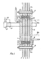
- the generator shown in Figure 1 comprises a plurality of electrodes, comprising two outer electrodes 1, 2 and a plurality of intervening electrodes 3, 4, 5, 6, 7 an electrolysis cell being formed between each adjacent pair of electrodes.
- Each of the electrodes is flat and rectangular and is stamped from a flat sheet of metal.
- Each electrode is mounted parallel to the other and it will be noted that the outer -electrodes 1, 2 are formed from substantially thicker sheet metal than the intervening electrodes.
- the intervening electrodes are larger in both height and width and project beyond the edges of the outer electrodes in both vertical directions and both horizontal directions.
- Adjacent pairs of electrodes are spaced apart by generally ring-shaped spacers 10, 11, 12, 13, 14, 15 of resilient material. These spacers may be circular rings or rectangular-shaped frames and are stamped from sheet material. This material may comprise rubber but must be resistant to the alkaline solutions forming the electrolyte. It will be noted that the spacers are aligned with each other, that the intervening spaces are aligned with each other and that the outer electrodes 1, 2 are aligned with each other.
- the electrodes and spacers are clamped together by appropriate means.
- these means comprise a plurality of bolts clamping the outer electrodes together: the bolts are spaced apart around the periphery of the cells (outwardly of the spacers) and each bolt extends through bores formed through the electrodes.
- Two of the bolts 16, 17 are shown and electrical insulation 16a, 17a is provided to insulate the metal bolts from the individual electrodes.
- the clamping means serves to clamp the electrodes and spacers together and in particular to compress the spacers, thus ensuring an effective peripheral seal between each spacer and the two electrodes between which it is clamped.
- the surfaces of the electrodes may be sandblasted to increase the effective surface area for the electrolysis process and to improve the strength of the spacers against any excessive pressures which may develop within the individual cells.
- An inlet aperture 18 for electrolyte is formed through the outer electrode 2, adjacent the bottom of the cell which is formed between electrodes 7 and 2. Alternatively, this inlet aperture may be provided adjacent the top of its cell, or at an intermediate position, as indicated in dotted lines at 18a, 18b respectively.
- An outlet aperture 19 for oxyhydrogen gas is formed through the outer electrode 1, adjacent the top of the cell formed between electrodes 1 and 3.
- a series of apertures 20 is provided in the intervening electrodes, adjacent the top of the respective cells for the transfer of the generated oxyhydrogen foam from the successive cells and towards the outlet 19, in the manner described in my GB-A-1 519 679.
- the electrodes 1-7 are otherwise imperforate.
- the outer electrodes 1, 2 are connected to the negative and positive poles, respectively, of a DC electrical supply 21.
- electrolyte basic water
- the gas which is produced fills the upper regions of the cells and depressed the level of electrolyte.
- Gas leaves the cells through the outlet 19 and fresh electrolyte enters continuously through inlet 18, 18a or 18b.
- All electrodes are simple and inexpensive to produce and can be produced by cutting or stamping from metal sheet.
- the seals provided by the spacers are simple and effective and the spacers are simple to form from suitable sheet material. Also, effective cooling is achieved as a result of the electrodes extending substantially beyond the spacers and into the surrounding air. The distance between electrodes is easily selected by selecting spacers of the appropriate thickness.
- the generator has high mechanical strength against any internal explosions which may occur by accident.
- the clamping bolts 16, 17 provide strength against forces acting perpendicular to the planes of the electrodes, whilst forces acting parallel to the planes of the electrodes are withstood by the spacers being compressed between the electrodes.
- the design is appropriate for very small electrolysis cells, which have the advantage of reducing current heating because of the smaller physical distance between cells. Therefore, a practical apparatus may comprise a large number of cells and make use of a rectified 220 volts A.C. supply.
- the structure shown in the drawing may be placed in a vessel which is filled with electrolyte, according to the teachings of Figure 11 of my GB-A-1 519 679 providing all exposed metal electrode surfaces are electrically insulated against the electrolyte which fills the vessel.
- the structure may be provided with cooling tubing between the outlet and inlet, in the manner taught by Figure 3 of my GB-A-1 519 679.
- the aperture or holes 20 may progessively increase in size from electrode-to-electrode, being smallest in electrode 7 and largest in electrode 3, to accommodate the increase in gas flow which occurs between the input cell and the output cell.
- the same effect may be produced by a progressive increase in the number of holes in the successive cells, or both by an increase in number and size. All these variations are indicated diagrammatically, and enlarged in scale, in Figure 1.
- the electrodes in Figure 1 are formed from iron, stainless steel or nickel, for example.
- the electrodes may be formed from copper sheet plated with a suitable metal or alloy.
- the copper exhibits high heat conductivity and high current conductivity (so that there is less loss by current flow through the electrodes).
- the plating metal or alloy is chosen to result in a low electrolysis voltage, for. example nickel.
- the plating need not cover the entire surface of the electrode, but only over the area within the peripheral spacers 15 (that is to say, only the area of the electrode which is in contact with the electrolyte). As a result, the electrolysis voltage (overvoltage) is minimised and high cooling efficiency is achieved and the electrodes are of minimal cost because the quantity of metal for the active electrode surface is minimised.
- Figure 2 shows, on reduced scale, a preferred arrangement comprising square electrodes, all of equal size, and circular spacer rings, the diameter of the spacer rings being equal to the side length of each electrode. Only electrode 7 and spacer 14 are seen. Assembly with this arrangement comprises simply stacking the electrodes and seals together, align-. ment being automatically ensured (because the ring diameter is the same as the side length of the electrodes) without special tooling being required. The projecting corners of the square electrodes still act as cooling fins.
- the electrodes are formed from copper sheet plated with metal or alloy over the area within the spacer rings, as previously mentioned and as indicated by shading at 7a. Bolt holes for bolts such as 16, 17 are shown at 7b.
- FIG. 3 shows diagrammatically use of any of the above described forms of generator (shown at 30) with a reservoir 31 of electrolyte.
- An outlet adjacent the bottom of the reservoir is connected to the generator inlet 18 by a tube 32, and the generator outlet 19 is connected by a tube 33 to a spout 34 in the reservoir above the free surface of electrolyte. From this spout, excess electrolyte returns to the reservoir volume and the oxyhydrogen gas passes upwards for use, for example in a flame torch.
- the head Ap (of the free surface of electrolyte in the reservoir above the top of the cells) is small, and advantageously a one- way valve (such as a ball valve) is connected in the inlet 18 to help establish the required flow direction of the electrolyte.
- a flow pump 36 is provided to help establish and maintain the required flow direction, and may be used for forcing a high rate of circulation if cooling is required.
- a temperature sensor 37 such as a bimetallic element, is provided in the outlet 19 to control a cooling fan 38 which is shown diagrammatically and which is directed at the generator 30.
- the control is such that the cooling fan is inhibited until an optimal temperature of the electrolyte is sensed by temperature sensor 37, and then the fan is energised to maintain this optimal temperature.
- the diameter of the outlet 19 and tube 33 are small, generally comparable to the size of the apertures 20, ensure a high pressure drop when the mixture of gas and electrolyte is dis-, charged into the reservoir, therefore providing good separation of the gas and electrolyte.
- Figure 4 shows diagrammatically use of any of the above described forms of generator (shown at 40) with a reservoir 41 of electrolyte and trapping means 45 for preventing water vapour and traces of electrolyte being entrained with the oxyhydrogen gas which is produced.
- this water vapour and traces of electrolyte will be present in the gas which is produced, adversely affecting the ability of the gas to burn properly in the flame torches for which it is used.
- the electrolyte inlet of the generator 40 is connected to the reservoir 41 by a tube 42 and a pump P is provided.
- the outlet of the generator is connected to the reservoir by a tube 43, terminating in a spout 44.
- the trapping means comprises a closed vessel and a tube 46 extends from the closed top of reservoir 41 to the bottom of the trap vessel.
- Tube 46 includes a pressure responsive ball valve 46a spring biassed to a normally open condition.
- a further tube 47 extends from the top of reservoir 41 and enters the top of the trap vessel, its outlet orifice 47a at least being of small diameter relative to tube 46.
- Tube 47 includes a spiral portion as shown for cooling purposes.
- An outlet tube 48 for oxyhydrogen gas extends through the top of the trap vessel.
- the gas passes through tube 46, and its valve 46a, and also through tube 47 to the trap vessel 45. If the gas production rate increases, the pressure within the reservoir will build up and eventually the valve 46a will be closed under the effect of this increased pressure. Gas then passes to the trap vessel only through tube 47, and the gas issuing from orifice 47a experiences a substantial decrease in pressure, causing condensation of the water vapour contained therein.
- gas at high pressure can carry more water vapour, and that a sudden decrease in pressure causes the vapour to condense. The condensed water collects in the trap vessel.
- an on/off switch 50 in the lines L from an A.C. supply to the D.C. generator 21 may be mechanically or otherwise linked to a changeover switch 51, so that each time the A.C. supply is switched on by switch 50, the switch 51 is changed over to reverse the polarity connections to the gas generator.
Landscapes
- Chemical & Material Sciences (AREA)
- Engineering & Computer Science (AREA)
- Chemical Kinetics & Catalysis (AREA)
- Electrochemistry (AREA)
- Materials Engineering (AREA)
- Metallurgy (AREA)
- Organic Chemistry (AREA)
- Inorganic Chemistry (AREA)
- Electrolytic Production Of Non-Metals, Compounds, Apparatuses Therefor (AREA)
- Feeding, Discharge, Calcimining, Fusing, And Gas-Generation Devices (AREA)
Claims (21)
Priority Applications (1)
| Application Number | Priority Date | Filing Date | Title |
|---|---|---|---|
| AT79300737T ATE275T1 (de) | 1978-05-15 | 1979-05-01 | Knallgasgenerator. |
Applications Claiming Priority (2)
| Application Number | Priority Date | Filing Date | Title |
|---|---|---|---|
| GB1960278 | 1978-05-15 | ||
| GB1960278 | 1978-05-15 |
Publications (3)
| Publication Number | Publication Date |
|---|---|
| EP0005597A2 EP0005597A2 (de) | 1979-11-28 |
| EP0005597A3 EP0005597A3 (en) | 1979-12-12 |
| EP0005597B1 true EP0005597B1 (de) | 1981-10-07 |
Family
ID=10132113
Family Applications (1)
| Application Number | Title | Priority Date | Filing Date |
|---|---|---|---|
| EP79300737A Expired EP0005597B1 (de) | 1978-05-15 | 1979-05-01 | Knallgasgenerator |
Country Status (10)
| Country | Link |
|---|---|
| US (1) | US4206029A (de) |
| EP (1) | EP0005597B1 (de) |
| JP (1) | JPS5933194B2 (de) |
| AT (1) | ATE275T1 (de) |
| AU (1) | AU525573B2 (de) |
| BR (1) | BR7902964A (de) |
| CA (1) | CA1123377A (de) |
| DE (1) | DE2960924D1 (de) |
| ES (1) | ES480475A1 (de) |
| HK (1) | HK41783A (de) |
Families Citing this family (36)
| Publication number | Priority date | Publication date | Assignee | Title |
|---|---|---|---|---|
| GB2081743B (en) * | 1980-07-31 | 1984-06-27 | Spirig Ernst | Cooling electrolysis apparatus generating gases |
| US4336122A (en) * | 1980-09-08 | 1982-06-22 | Ernst Spirig | Electrolysis apparatus |
| US4339324A (en) * | 1980-12-03 | 1982-07-13 | Henes Products Corp. | Polycell gas generator |
| US4424106A (en) | 1981-11-27 | 1984-01-03 | Institut Elektrosvarki Imeni E.O. Patona | Electrolytic filter press cell for producing a mixture of hydrogen and oxygen |
| DE3218259A1 (de) * | 1982-05-14 | 1983-11-24 | Henes Products Corp., 85018 Phoenix, Ariz. | Mehrzelliger gasgenerator |
| US4425215A (en) | 1982-09-27 | 1984-01-10 | Henes Products Corp. | Gas generator |
| JPS59156317A (ja) * | 1983-02-28 | 1984-09-05 | 金沢工業株式会社 | コ−ヒ−等の抽出装置 |
| CA1339406C (en) * | 1989-02-10 | 1997-09-02 | Bernard Lerner | Method and apparatus for manufacture of sleeves |
| GB2238059A (en) * | 1989-11-17 | 1991-05-22 | Command International Inc | Electrolytic gas generating apparatus for producing a combustible mixture of hydrogen and oxygen by electrolysis of water for particular use in gas welding |
| JPH08507828A (ja) * | 1993-03-15 | 1996-08-20 | ライディングズ ピーティーワイ リミテッド | 電解製造装置 |
| US5614069A (en) * | 1996-06-12 | 1997-03-25 | Lin; I-Chuan | Apparatus for producing electrolytically and collecting separately two gases |
| US5827053A (en) * | 1997-07-25 | 1998-10-27 | Costa; Larry J. | Positive flow purge system for microflame torch |
| US6123246A (en) * | 1997-08-01 | 2000-09-26 | Costa; Larry J. | Dual intermittent microflame system for discrete point soldering |
| US5934541A (en) * | 1997-08-01 | 1999-08-10 | Costa; Larry J. | Dual intermittent microflame system for discrete point soldering |
| US7001146B1 (en) | 2003-12-31 | 2006-02-21 | Hydro-Laser Limited Partnership | Electric fan cooling of hydraulic pump |
| FR2882065A1 (fr) * | 2005-03-21 | 2006-08-18 | Air Liquide | Installation d'electrolyse de conception sure |
| WO2008118088A1 (en) * | 2007-03-26 | 2008-10-02 | Lq Holding Ab | A gas reactor system |
| US20080257719A1 (en) * | 2007-04-21 | 2008-10-23 | Ted Suratt | Apparatus And Method For Making Flammable Gas |
| US20100209360A1 (en) * | 2007-04-21 | 2010-08-19 | Lsg Holdings, Inc. | Method for Making a Gas from an Aqueous Fluid, Product of the Method, and Apparatus Therefor |
| WO2010002308A1 (en) * | 2008-06-23 | 2010-01-07 | Cardilogus International Ltd | A thermo electric gas reactor system and gas reactor |
| KR100862924B1 (ko) * | 2008-07-14 | 2008-10-13 | 황부성 | 수소산소 혼합가스 발생장치 |
| KR100862923B1 (ko) * | 2008-07-14 | 2008-10-13 | 황부성 | 수소산소 혼합가스 발생시스템 |
| ES2359217B1 (es) * | 2008-08-06 | 2012-04-10 | Jose Antonio Martinez Cao | Aparato productor de gases combustibles por electrolisis. |
| US20100132634A1 (en) * | 2008-12-01 | 2010-06-03 | Jeff Selano | Electronic System for an Internal Combustion Engine |
| WO2010080018A1 (en) * | 2009-01-06 | 2010-07-15 | Hydrogen Fuelsaver Sdn Bhd | An oxyhydrogen generator |
| US8147661B2 (en) * | 2009-08-31 | 2012-04-03 | Green On Demand Gmbh | Unit for the electrolysis of water |
| US20110100328A1 (en) * | 2009-10-29 | 2011-05-05 | Prime Core Tech LLC. | Electrolysis apparatus and related devices and methods |
| DE102010054643A1 (de) * | 2010-12-15 | 2012-06-21 | Bayer Material Science Ag | Elektrolyseur mit spiralförmigem Einlaufschlauch |
| JP6247845B2 (ja) * | 2013-06-28 | 2017-12-13 | 豊商事有限会社 | エンジンシステム |
| ITPD20130280A1 (it) * | 2013-10-09 | 2015-04-10 | Idropan Dell Orto Depuratori S R L | Apparecchiatura per il trattamento di un fluido |
| IT201700032899A1 (it) * | 2017-03-24 | 2018-09-24 | Varmo S R L | Apparato di produzione ossidrogeno |
| US10767269B2 (en) * | 2017-06-21 | 2020-09-08 | Vital Tech, LLC | Electrolysis device |
| CN113260740B (zh) * | 2019-01-10 | 2024-12-17 | 松下知识产权经营株式会社 | 镀敷用图案版以及布线基板的制造方法 |
| CA3127358A1 (en) | 2019-02-01 | 2020-08-06 | Aquahydrex, Inc. | Electrochemical system with confined electrolyte |
| JP7446647B1 (ja) * | 2022-08-26 | 2024-03-11 | T・D・S株式会社 | 酸水素混合ガス発生装置及び酸水素混合ガス発生方法 |
| WO2024204154A1 (ja) * | 2023-03-27 | 2024-10-03 | 好正 ▲高▼部 | 酸水素ガス生成装置 |
Family Cites Families (9)
| Publication number | Priority date | Publication date | Assignee | Title |
|---|---|---|---|---|
| NL129924C (de) * | 1964-10-12 | 1970-06-15 | ||
| DE2159246B2 (de) * | 1971-11-30 | 1977-12-08 | Götz, Friedrich, DipL-Phys, 5628 Heiligenhaus | Vorrichtung zur erzeugung eines gemisches von wasserstoff und sauerstoff |
| DE2202739C2 (de) * | 1972-01-20 | 1983-08-18 | Ernst Dipl.-Ing. 8640 Rapperswil Spirig | Wasserzersetzer |
| US4014777A (en) * | 1973-07-20 | 1977-03-29 | Yull Brown | Welding |
| AR206894A1 (es) * | 1973-08-03 | 1976-08-31 | Brown Y | Un metodo para efectuar operaciones de soldadura cobre soldadura y soldadura oxidrica en la cual el hidrogeno y oxigeno se generan electroliticamente como mezcla en proporciones substancialmente estequiometricas y aparato para ilevarlo a la practica |
| DE2349286C3 (de) * | 1973-10-01 | 1982-11-18 | Götz, Friedrich, Dipl.-Phys., 5628 Heiligenhaus | Vielfachelektrolysezelle zur Erzeugung eines Gemisches von Wasserstoff und Sauerstoff |
| CA1032892A (en) * | 1974-11-13 | 1978-06-13 | Gow Enterprises Ltd. | Module electrode assembly for electrolytic cells |
| GB1518762A (en) * | 1976-02-17 | 1978-07-26 | Paterson Candy Int | Bipolar cell |
| GB1519679A (en) * | 1976-12-09 | 1978-08-02 | Spirig Ernst | Water decomposing apparatus |
-
1979
- 1979-05-01 DE DE7979300737T patent/DE2960924D1/de not_active Expired
- 1979-05-01 EP EP79300737A patent/EP0005597B1/de not_active Expired
- 1979-05-01 AT AT79300737T patent/ATE275T1/de active
- 1979-05-07 US US06/036,290 patent/US4206029A/en not_active Expired - Lifetime
- 1979-05-08 AU AU46842/79A patent/AU525573B2/en not_active Expired
- 1979-05-11 ES ES480475A patent/ES480475A1/es not_active Expired
- 1979-05-14 CA CA327,541A patent/CA1123377A/en not_active Expired
- 1979-05-14 BR BR7902964A patent/BR7902964A/pt unknown
- 1979-05-15 JP JP54059608A patent/JPS5933194B2/ja not_active Expired
-
1983
- 1983-10-13 HK HK417/83A patent/HK41783A/xx not_active IP Right Cessation
Also Published As
| Publication number | Publication date |
|---|---|
| DE2960924D1 (en) | 1981-12-17 |
| BR7902964A (pt) | 1979-11-27 |
| EP0005597A2 (de) | 1979-11-28 |
| US4206029A (en) | 1980-06-03 |
| ATE275T1 (de) | 1981-10-15 |
| ES480475A1 (es) | 1980-01-16 |
| CA1123377A (en) | 1982-05-11 |
| EP0005597A3 (en) | 1979-12-12 |
| HK41783A (en) | 1983-10-21 |
| AU525573B2 (en) | 1982-11-11 |
| AU4684279A (en) | 1979-11-22 |
| JPS556487A (en) | 1980-01-17 |
| JPS5933194B2 (ja) | 1984-08-14 |
Similar Documents
| Publication | Publication Date | Title |
|---|---|---|
| EP0005597B1 (de) | Knallgasgenerator | |
| US3188242A (en) | Fuel cell battery containing flat carbon electrodes | |
| US3278336A (en) | Fuel cell and electrode unit therefor | |
| US4424105A (en) | Gas generator with regulated current source | |
| US4659559A (en) | Gas fueled fuel cell | |
| US4374014A (en) | High pressure electrolytic oxygen generator | |
| JPH09504053A (ja) | 電解システムの改良 | |
| EP0558345B1 (de) | Entwurfs- und Herstellungsverfahren einer mit festen ionenleitenden Elektrolyt versehene Anordnung | |
| US20250236972A1 (en) | Alkaline Electrolyzer with Cooled Bipolar Electrode | |
| GB2296124A (en) | Bipolar plate for fuel cells comprises single integral metal sheet having raised regions forming contact surfaces and gas flow paths | |
| KR890002062B1 (ko) | 전기 화학 단자 유니트 | |
| US5614069A (en) | Apparatus for producing electrolytically and collecting separately two gases | |
| WO2018182004A1 (ja) | 外部ヘッダー型複極式エレメント、外部ヘッダー型複極式電解槽、及び水素製造方法 | |
| CN120169627B (zh) | 涂布模头和涂布装置 | |
| PL133880B1 (en) | Permeable electrode for an electrolytic cell | |
| CA1154718A (en) | Electrode for monopolar filter press cells | |
| US6200435B1 (en) | Ion exchange membrane electrolyzer | |
| KR830000621B1 (ko) | 폭발 가스발생기 | |
| CA1177013A (en) | Electrolysis apparatus | |
| US4424106A (en) | Electrolytic filter press cell for producing a mixture of hydrogen and oxygen | |
| RU2056983C1 (ru) | Электролизно-водный сварочный аппарат | |
| KR102705353B1 (ko) | 전해조 | |
| CN1983701B (zh) | 螺旋缠绕式燃料电池组 | |
| RU2073594C1 (ru) | Устройство для газопламенной обработки материалов | |
| JP2005248244A (ja) | 水素・酸素混合ガス発生装置 |
Legal Events
| Date | Code | Title | Description |
|---|---|---|---|
| PUAI | Public reference made under article 153(3) epc to a published international application that has entered the european phase |
Free format text: ORIGINAL CODE: 0009012 |
|
| PUAL | Search report despatched |
Free format text: ORIGINAL CODE: 0009013 |
|
| AK | Designated contracting states |
Designated state(s): AT CH DE FR IT NL SE |
|
| AK | Designated contracting states |
Designated state(s): AT CH DE FR IT NL SE |
|
| 17P | Request for examination filed | ||
| ITF | It: translation for a ep patent filed | ||
| GRAA | (expected) grant |
Free format text: ORIGINAL CODE: 0009210 |
|
| AK | Designated contracting states |
Designated state(s): AT CH DE FR IT NL SE |
|
| REF | Corresponds to: |
Ref document number: 275 Country of ref document: AT Date of ref document: 19811015 Kind code of ref document: T |
|
| REF | Corresponds to: |
Ref document number: 2960924 Country of ref document: DE Date of ref document: 19811217 |
|
| ITTA | It: last paid annual fee | ||
| EAL | Se: european patent in force in sweden |
Ref document number: 79300737.8 |
|
| PGFP | Annual fee paid to national office [announced via postgrant information from national office to epo] |
Ref country code: NL Payment date: 19950531 Year of fee payment: 17 |
|
| PGFP | Annual fee paid to national office [announced via postgrant information from national office to epo] |
Ref country code: AT Payment date: 19960514 Year of fee payment: 18 |
|
| PGFP | Annual fee paid to national office [announced via postgrant information from national office to epo] |
Ref country code: SE Payment date: 19960517 Year of fee payment: 18 |
|
| PG25 | Lapsed in a contracting state [announced via postgrant information from national office to epo] |
Ref country code: NL Effective date: 19961201 |
|
| NLV4 | Nl: lapsed or anulled due to non-payment of the annual fee |
Effective date: 19961201 |
|
| PG25 | Lapsed in a contracting state [announced via postgrant information from national office to epo] |
Ref country code: AT Effective date: 19970501 |
|
| PG25 | Lapsed in a contracting state [announced via postgrant information from national office to epo] |
Ref country code: SE Effective date: 19970502 |
|
| PGFP | Annual fee paid to national office [announced via postgrant information from national office to epo] |
Ref country code: DE Payment date: 19970509 Year of fee payment: 19 |
|
| PGFP | Annual fee paid to national office [announced via postgrant information from national office to epo] |
Ref country code: FR Payment date: 19970513 Year of fee payment: 19 |
|
| EUG | Se: european patent has lapsed |
Ref document number: 79300737.8 |
|
| PGFP | Annual fee paid to national office [announced via postgrant information from national office to epo] |
Ref country code: CH Payment date: 19980507 Year of fee payment: 20 |
|
| PG25 | Lapsed in a contracting state [announced via postgrant information from national office to epo] |
Ref country code: FR Free format text: LAPSE BECAUSE OF NON-PAYMENT OF DUE FEES Effective date: 19980531 |
|
| PG25 | Lapsed in a contracting state [announced via postgrant information from national office to epo] |
Ref country code: DE Free format text: LAPSE BECAUSE OF NON-PAYMENT OF DUE FEES Effective date: 19990302 |
|
| REG | Reference to a national code |
Ref country code: FR Ref legal event code: ST |
|
| PG25 | Lapsed in a contracting state [announced via postgrant information from national office to epo] |
Ref country code: CH Free format text: LAPSE BECAUSE OF EXPIRATION OF PROTECTION Effective date: 19990430 |
|
| REG | Reference to a national code |
Ref country code: CH Ref legal event code: PL |
|
| PLBE | No opposition filed within time limit |
Free format text: ORIGINAL CODE: 0009261 |
|
| STAA | Information on the status of an ep patent application or granted ep patent |
Free format text: STATUS: NO OPPOSITION FILED WITHIN TIME LIMIT |